oil type DODGE TRUCK 1993 Service User Guide
[x] Cancel search | Manufacturer: DODGE, Model Year: 1993, Model line: TRUCK, Model: DODGE TRUCK 1993Pages: 1502, PDF Size: 80.97 MB
Page 44 of 1502
•
LUBRICATION
AND
MAINTENANCE
0 - 25
CAUTION:
Do not
over-tighten
the
drain
and fill
hole
plugs.
Over-tightening
can strip the
hole
threads
and/or crack
the
aluminum housing.
(5) Install the drain hole plug (Figs. 4 and 5) in
the transfer case. Tighten the drain hole plug to 27 N*m (20 ft-lbs) torque. (6) Fill the transfer case to the bottom edge of the
fill hole (Figs. 4 and 5) with: • MOPAR®ATF PLUS or an equivalent Dexron II®
ATF for NP241 transfer cases
• Multi-purpose gear oil (API GL-5) or engine oil (API SG, SG/CD or SG/CE) for NP205 transfer cases. (7) Install the fill hole plug (Figs. 4 and 5) in the
transfer case. Tighten the plug to 27 N«m (20 ft-lbs) torque.
(8) Remove the support and lower the vehicle.
FLUID SPECIFICATION
• MOPAR®ATF PLUS or an equivalent Dexron II®
ATF for NP241 transfer cases • Multi-purpose gear oil (API GL-5) or engine oil (API SG, SG/CD or SG/CE) for NP205 transfer cases
NP20I
MULTI-PURPOSE GEAR OIL/ENGINE
OIL
SELECTION
MULTI-PURPOSE GEAR OIL-if the anticipated
minimum temperature will: • Be above 32°C (90°F)-use SAE 140, API GL-5;
• Decrease to as low as -23°C (-10°F)-use SAE 90,
API GL-5; and • Be below -23°C (-10°F)-use SAE 80, API GL-5. ENGINE OIL—if the anticipated minimum tem
perature will be: ® Above 0°C (32°F)-use SAE 50, API SG, SG/CD or
SG/CE;
• Below 0°C (32°F)-use SAE 30, API SG, SG/CD or SG/CE.
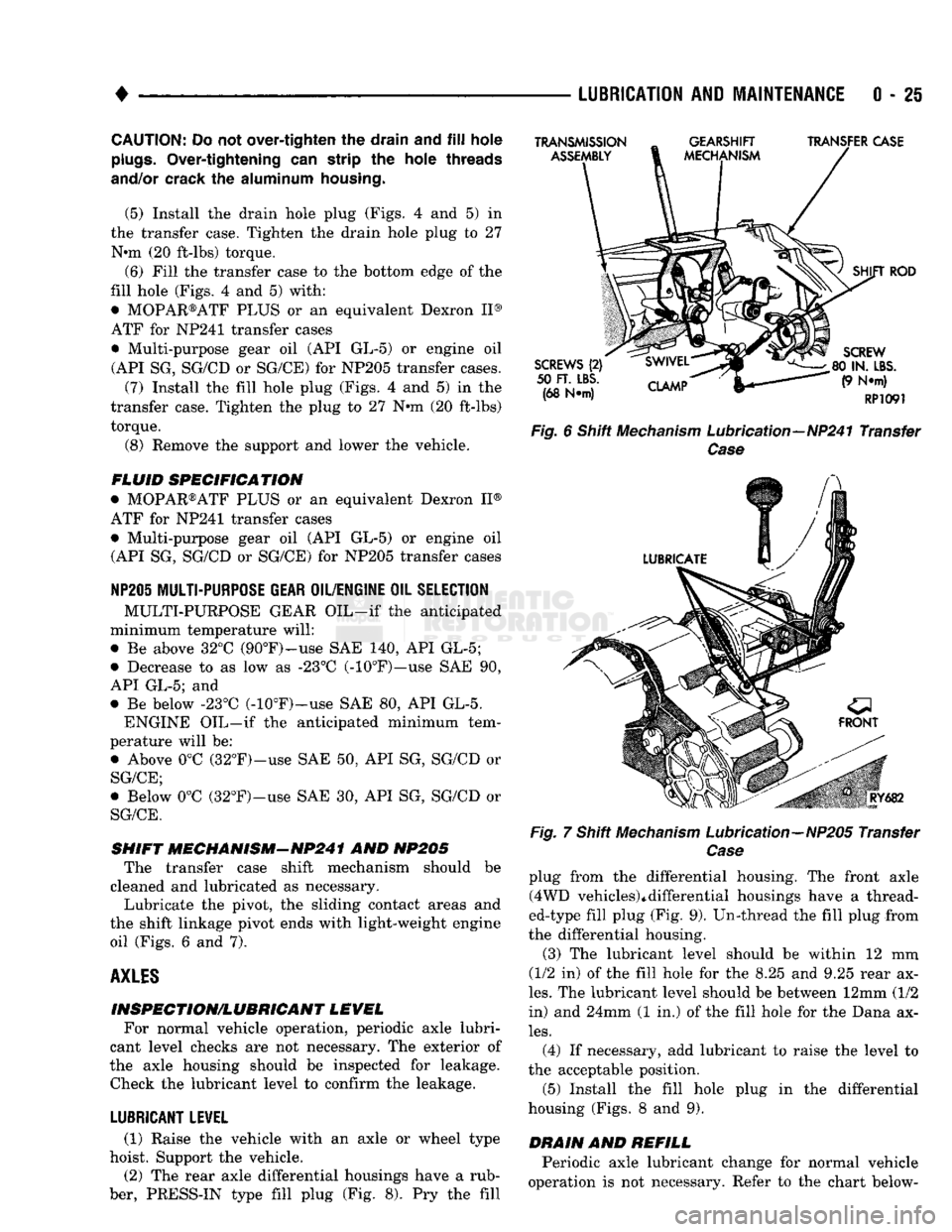
SHIFT MECHANISM-NP241 AND NP205 The transfer case shift mechanism should be
cleaned and lubricated as necessary.
Lubricate the pivot, the sliding contact areas and
the shift linkage pivot ends with light-weight engine oil (Figs. 6 and 7).
AXLES
INSPECTION/LUBRICANT LEVEL For normal vehicle operation, periodic axle lubri
cant level checks are not necessary. The exterior of
the axle housing should be inspected for leakage. Check the lubricant level to confirm the leakage.
LUBRICANT LEVEL
(1) Raise the vehicle with an axle or wheel type
hoist. Support the vehicle.
(2) The rear axle differential housings have a rub
ber, PRESS-IN type fill plug (Fig. 8). Pry the fill
TRANSMISSION
ASSEMBLY
GEARSHIFT
MECHANISM TRANSFER CASE
SCREWS
(2)
50
FT. LBS.
(68 N*m)
CLAMP
SHIFT
ROD
SCREW
80 IN.
LBS.
(9 N*m)
RP1091
Fig.
6 Shift
Mechanism
Lubrication—NP241 Transfer
Case
Fig.
RY682
7 Shift
Mechanism
Lubrication—NP205 Transfer
Case
plug from the differential housing. The front axle (4WD vehicles)*differential housings have a thread
ed-type fill plug (Fig. 9). Un-thread the fill plug from
the differential housing.
(3) The lubricant level should be within 12 mm
(1/2 in) of the fill hole for the 8.25 and 9.25 rear ax
les.
The lubricant level should be between 12mm (1/2
in) and 24mm (1 in.) of the fill hole for the Dana ax
les.
(4) If necessary, add lubricant to raise the level to
the acceptable position.
(5) Install the fill hole plug in the differential
housing (Figs. 8 and 9).
DRAIN
AND
REFILL
Periodic axle lubricant change for normal vehicle
operation is not necessary. Refer to the chart below-
Page 47 of 1502
0
- 28
LUBRICATION
AND
MAINTENANCE
•
CHASSIS AND BODY
page
Body
Component Mechanisms
32
Front
Suspension
Ball
Joints
28
Front
Wheel Bearings
29
Headlamps
32
Lower
and
Upper Suspension
Arm
Bushings
.... 30
Manual
Steering Gear
28
STEERING
LINKAGE
INSPECTION When
a
vehicle
is
raised
for
maintenance under
the vehicle,
all
steering components should
be
checked.
LUBRICATION SCHEDULE The steering linkage
is
lubricated with
a
chassis
lubricant. However,
it is
recommended that
the
link
age
be
inspected
and
lubricated after each:
•
24 000 km
(15,000 miles) interval
or
every
6
months,
for 2WD
vehicles subject
to the
LIGHT
DUTY CYCLE Maintenance Schedule
•
9 600 km
(6,000 miles) interval
or
every
6
months,
for
2WD
vehicles subject
to the
HEAVY DUTY
CY
CLE Maintenance Schedule
•
12 000 km
(7,500 miles) interval
or
every
6
months,
for 4WD
vehicles subject
to the
LIGHT DUTY CYCLE Maintenance Schedule
•
9 600 km
(6,000 miles) interval
or
every
6
months,
for
4WD
vehicles subject
to the
HEAVY DUTY
CY
CLE Maintenance Schedule.
LUBRICATION (1) Inspect
the
steering linkage
for
looseness
and
excessive wear. (2) Replace,
all
ruptured seals
and
damaged steer
ing linkage components. Damaged seals should
be re
placed
to
prevent leakage
and
contamination
of the
lubricant.
CAUTION:
Use
care
to
prevent lubricant from
con
tacting
the
brake rotors.
(3) Lubricate
the
steering linkage:
• Clean
the
Zerk type lubrication fittings
on the tie-
rod
and
center link ball-stud ends
• Lubricate
the
ball studs with MOPAR®Multi-Mile- age Lubricant
• Wipe
the
excess lubricant from
the
exterior sur
faces
of the
ball joints
page
Power
Brake System
30
Power
Steering System
. . 29
Rear
Wheel Bearings
30
Speedometer Cable
33
Steering Linkage
28
Tires
32
FRONT
SUSPENSION
BALL JOINTS
INSPECTION When
a
vehicle
is
raised
for
lubrication/general
maintenance,
the
ball joints should
be
inspected.
LUBRICATION SCHEDULE The front suspension ball joints
are
lubricated dur
ing manufacture with
a
long-life chassis lubricant.
However,
it is
recommended that
the
ball joints
be
inspected
and the
studs lubricated:
•
At
each
36 000 km
(22,500 miles) interval
or
every
2 years,
for
vehicles subject
to the
LIGHT DUTY
CY
CLE Maintenance Schedule
•
At
each
9 600 km
(6,000 miles) interval
or
every
2
years,
for
vehicles subject
to the
HEAVY DUTY
CY
CLE Maintenance Schedule.
4WD vehicles that
are
frequently driven
off-
road should
be
lubricated
at
every engine
oil
change.
LUBRICATION (1) Inspect
the
front suspension. Examine
the
ball
studs
for
looseness
and
excessive wear. (2) Replace
all
torn ball-stud seals
and
damaged
ball joints. Damaged seals should
be
replaced
to
pre vent leakage
and
contamination.
CAUTION:
Use
care
to
prevent lubricant from
con
tacting
the
brake rotors.
(3) Lubricate
the
ball studs:
• Clean
the
Zerk type lubrication fittings
on the
ball-stud ends
• Lubricate
the
ball studs with MOPAR®Multi-Mile-age Lubricant
• Wipe
the
excess lubricant from
the
exterior sur
faces
of the
ball joints
MANUAL
STEERING
GEAR
LUBRICATION Manual steering gears
are
permanently lubricated
during manufacture. Periodic lubrication
is not
nec
essary.
Page 54 of 1502
•
FRONT SUSPENSION
AND
AXLE
2 - 1
CONTENTS
page
FRONT SUSPENSION—2WD VEHICLES
......
7
FRONT SUSPENSION—4WD VEHICLES
14
FRONT WHEEL
ALIGNMENT
...............
3
GENERAL INFORMATION
1
page
MODEL
44
FRONT AXLE
17
MODEL
80
FRONT AXLE
49
TORQUE SPECIFICATIONS
75
GENERAL
INFORMATION
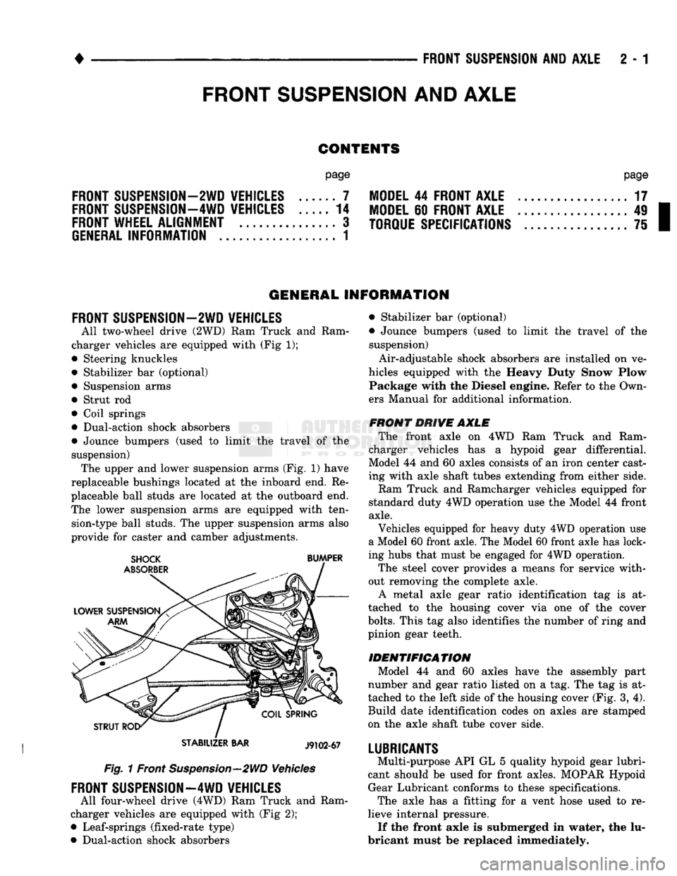
FRONT SUSPENSION—2WD VEHICLES
All two-wheel drive (2WD)
Ram
Truck
and
Ram
charger vehicles
are
equipped with (Fig
1);
• Steering knuckles
• Stabilizer
bar
(optional) • Suspension arms
• Strut
rod
• Coil springs
• Dual-action shock absorbers
• Jounce bumpers (used
to
limit
the
travel
of the
suspension) The upper and lower suspension arms (Fig.
1)
have
replaceable bushings located
at the
inboard end.
Re
placeable ball studs
are
located
at
the
outboard end.
The lower suspension arms
are
equipped with ten sion-type ball studs. The upper suspension arms also
provide
for
caster
and
camber adjustments.
STABILIZER
BAR
J9102-67
Fig. 1 Front Suspension—2WD Vehicles
FRONT SUSPENSION—4WD VEHICLES
All four-wheel drive (4WD) Ram Truck
and
Ram
charger vehicles
are
equipped with (Fig
2);
• Leaf-springs (fixed-rate type)
• Dual-action shock absorbers • Stabilizer
bar
(optional)
• Jounce bumpers (used
to
limit
the
travel
of the
suspension)
Air-adjustable shock absorbers
are
installed
on
ve
hicles equipped with
the
Heavy Duty Snow Plow Package with
the
Diesel engine. Refer
to
the Own
ers Manual
for
additional information.
FRONT DRIVE AXLE The front axle
on 4WD Ram
Truck
and
Ram
charger vehicles
has a
hypoid gear differential.
Model
44
and
60
axles consists
of
an iron center cast
ing with axle shaft tubes extending from either side.
Ram Truck
and
Ramcharger vehicles equipped
for
standard duty 4WD operation use
the
Model
44
front
axle.
Vehicles equipped
for
heavy duty 4WD operation
use
a Model 60 front axle. The Model 60 front axle has lock
ing hubs that must
be
engaged
for
4WD operation.
The steel cover provides
a
means
for
service with
out removing
the
complete axle. A metal axle gear ratio identification
tag is at
tached
to the
housing cover
via one of the
cover
bolts.
This
tag
also identifies
the
number
of
ring and
pinion gear teeth.
IDENTIFICATION Model
44 and 60
axles have
the
assembly part
number
and
gear ratio listed
on a
tag. The
tag
is at
tached
to
the
left side
of
the housing cover (Fig.
3,
4).
Build date identification codes
on
axles
are
stamped
on
the
axle shaft tube cover side.
LUBRICANTS
Multi-purpose API
GL
5
quality hypoid gear lubri
cant should
be
used
for
front axles. MOPAR Hypoid Gear Lubricant conforms
to
these specifications. The axle
has a
fitting
for a
vent hose used
to re
lieve internal pressure. If the front axle
is
submerged
in
water,
the
lu
bricant must
be
replaced immediately.
FRONT
SUSPENSION
AND
AXLE
Page 60 of 1502
•
FRONT
SUSPENSION
AND
AXLE
2 • 7
FRONT SUSPENSION
—2WD
VEHICLES
INDEX
page
Coil Springs
9
Lower Ball Stud
. 10
Lower Suspension
Arm 10
Lower Suspension
Arm
Bushing
11
Lower Suspension
Arm
Strut
8
Service
Information
7
Shock
Absorber
9
page
Stabilizer
Bar 8
Steering Knuckle
13
Upper Ball Stud
11
Upper Suspension
Arm 11
Upper Suspension
Arm
Bushing Replacement
. . . 12
Wheel
Hub and
Bearings
7
SERVICE
INFORMATION
Periodic lubrication of the front suspension (steer
ing) system components is required. Refer to Group 0, Lubrication And Maintenance for the service in
terval.
Rubber bushings must never be lubricated.
All front suspension components that are
cushioned by rubber should be tightened with
the suspension system at the normal height.
WHEEL
HUB
AND
BEARINGS
REMOVAL (1) Block the brake pedal in the up (non-depressed)
position.
(2) Raise and support the vehicle.
(3) Remove the wheel.
(4) Remove bolts from the disc brake caliper.
(5) Separate the disc brake caliper from the rotor.
Position and support the caliper away from the im
mediate work area. Do not allow the caliper to
hang from the brake fluid hose.
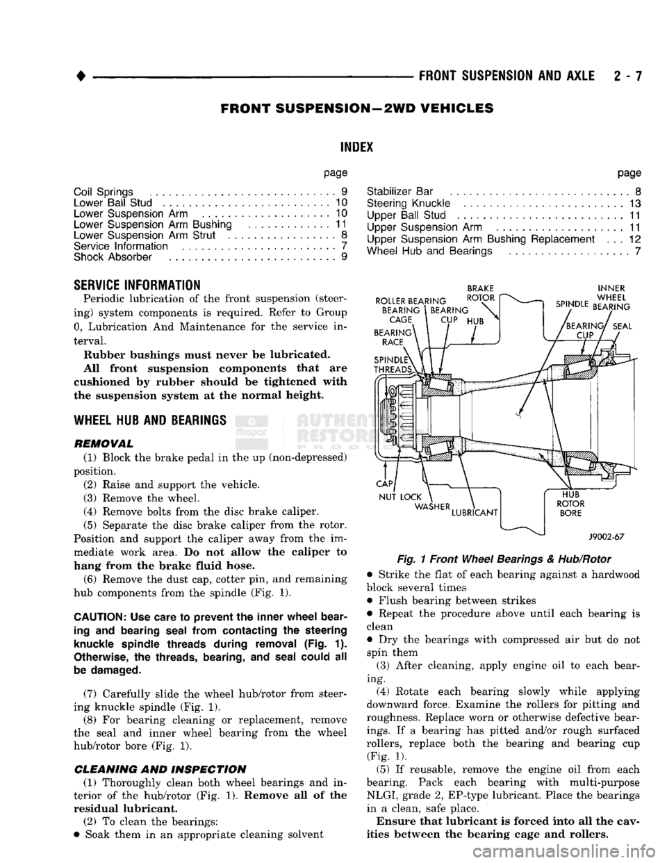
(6) Remove the dust cap, cotter pin, and remaining
hub components from the spindle (Fig. 1).
CAUTION:
Use care
to
prevent
the
inner wheel bear
ing
and
bearing seal from contacting
the
steering
knuckle spindle threads during removal
(Fig. 1).
Otherwise,
the
threads, bearing,
and
seal could
all
be damaged.
(7) Carefully slide the wheel hub/rotor from steer
ing knuckle spindle (Fig. 1).
(8) For bearing cleaning or replacement, remove
the seal and inner wheel bearing from the wheel
hub/rotor bore (Fig. 1).
CLEANING AND INSPECTION (1) Thoroughly clean both wheel bearings and in
terior of the hub/rotor (Fig. 1). Remove all of the residual lubricant.
(2) To clean the bearings:
• Soak them in an appropriate cleaning solvent
BRAKE
INNER
Fig.
1 Front
Wheel
Bearings
&
Hub/Rotor
• Strike the flat of each bearing against a hardwood
block several times • Flush bearing between strikes
• Repeat the procedure above until each bearing is
clean
• Dry the bearings with compressed air but do not spin them
(3) After cleaning, apply engine oil to each bear
ing. (4) Rotate each bearing slowly while applying
downward force. Examine the rollers for pitting and
roughness. Replace worn or otherwise defective bear
ings.
If a bearing has pitted and/or rough surfaced
rollers, replace both the bearing and bearing cup (Fig. 1).
(5) If reusable, remove the engine oil from each
bearing. Pack each bearing with multi-purpose NLGI, grade 2, EP-type lubricant. Place the bearings
in a clean, safe place.
Ensure that lubricant is forced into all the cav
ities between the bearing cage and rollers.
Page 132 of 1502
•
REAR
SUSPENSION
AND
AXLE
3 - 3
REAR SUSPENSION—2WD
and 4WD
VEHICLES
SPRING
AND
SHOCK DIAGNOSIS
A squeak noise from the shock absorber or spring
bushings can be produced if movement between the
rubber bushings and the metal occurs. This noise can usually be stopped by tightening the attaching nuts.
If the squeak noise persists, inspect for damaged and
worn bushings, and attaching components. Repair as
necessary if any of these conditions exist. The shock absorber bushings do not require any
type of lubrication. Do not lubricate the bushings to reduce bushing noise. Grease or mineral oil-base lu
bricants will deteriorate the bushing rubber. The shock absorbers are not reflllable or adjust
able.
If a malfunction occurs, the shock absorber
must be replaced. To test a shock absorber, hold it in an upright position and force the piston into and out
of the cylinder four or five times. The action through
out each stroke should be smooth and even. The spring eye and shock absorber bushings do not
require any type of lubrication. Do not attempt to stop spring bushing noise by lubricating them.
Grease and mineral oil-base lubricants will deterio
rate the bushing rubber. If the vehicle is used for severe, off-road operation,
the springs should be examined periodically. Check for broken and shifted leafs, loose and missing clips, and broken center bolts.
VEHICLE LOADING
AND
WEIGHT DISTRIBUTION
A vehicle should always be loaded so the vehicle
weight center-line is located immediately forward of
the rear axle. Correct vehicle loading provides proper
front tire-to-road contact. This results in maximum
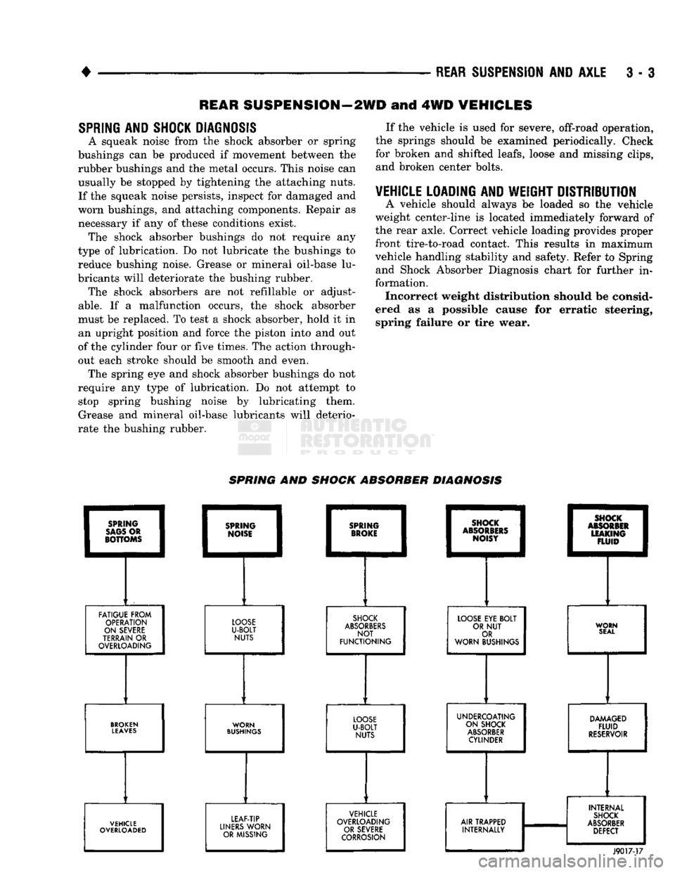
vehicle handling stability and safety. Refer to Spring and Shock Absorber Diagnosis chart for further in
formation. Incorrect weight distribution should be consid
ered as a possible cause for erratic steering, spring failure or tire wear. SPRING AND SHOCK ABSORBER DIAGNOSIS
FATIGUE FROM
OPERATION
ON SEVERE
TERRAIN
OR
OVERLOADING
LOOSE
U-BOLT
NUTS
SHOCK
ABSORBERS
NOT
FUNCTIONING
LOOSE
EYE
BOLT
OR
NUT
OR
WORN BUSHINGS WORN
SEAL
BROKEN
LEAVES
WORN
BUSHINGS
UNDERCOATING
ON SHOCK
ABSORBER
CYLINDER
DAMAGED
FLUID
RESERVOIR
VEHICLE
OVERLOADED LEAF-TIP
LINERS
WORN OR MISSING VEHICLE
OVERLOADING OR SEVERE
CORROSION
AIR TRAPPED
INTERNALLY INTERNAL
SHOCK
ABSORBER
DEFECT
J9017-17
Page 155 of 1502
3
- 28
REAR
SUSPENSION
AND
AXLE
•
SURE-GRIP
DIFFERENTIAL
SERVICE
GENERAL
INFORMATION
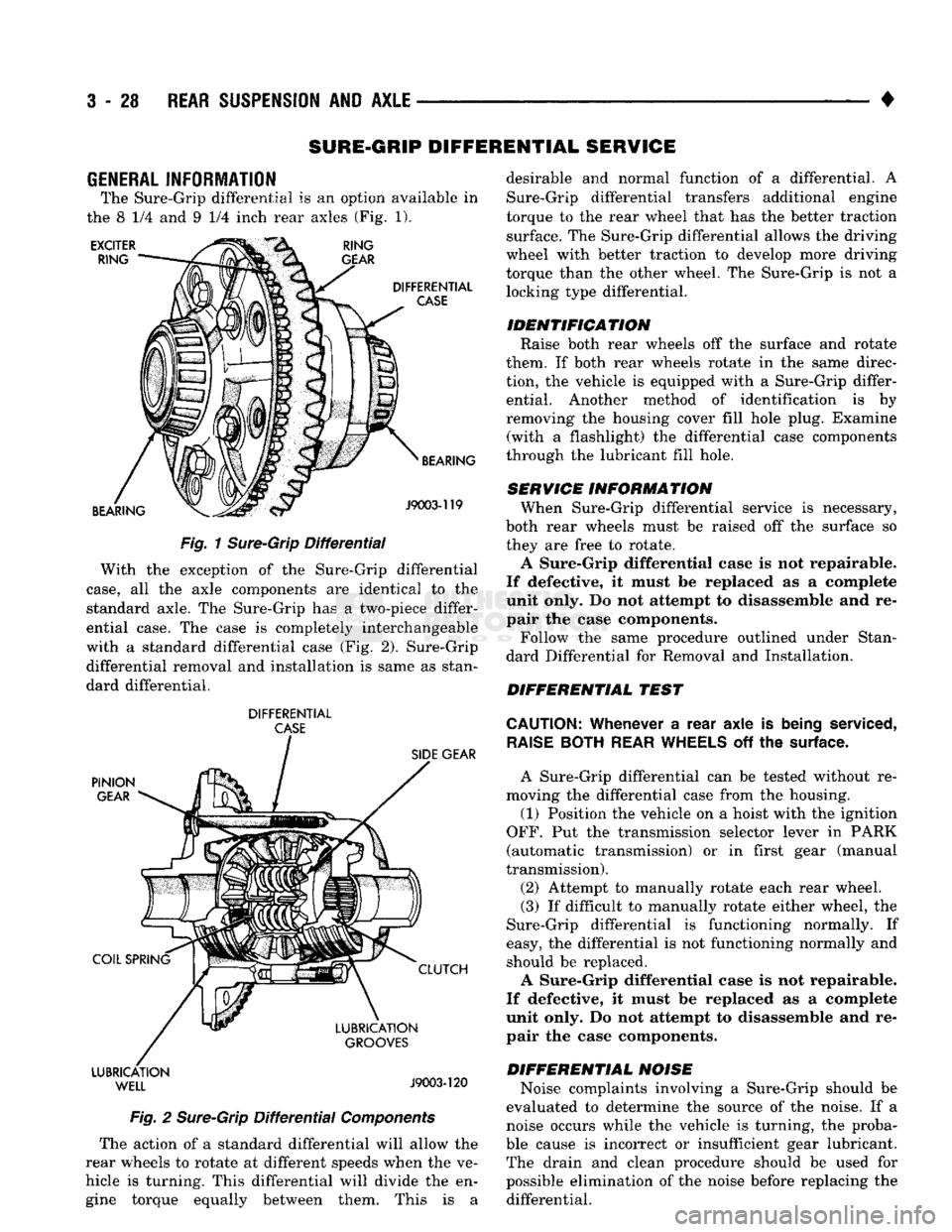
The Sure-Grip differential
is an
option available
in
the
8 1/4 and 9 1/4
inch rear axles
(Fig. 1).
EXCITER
RING RING
GEAR
DIFFERENTIAL
CASE
BEARING BEARING
J9003-119
Fig.
1
Sure-Grip
Differential
With
the
exception
of the
Sure-Grip differential
case,
all the
axle components
are
identical
to the
standard axle.
The
Sure-Grip
has a
two-piece differ
ential case.
The
case
is
completely interchangeable
with
a
standard differential case
(Fig. 2).
Sure-Grip differential removal
and
installation
is
same
as
stan
dard differential.
DIFFERENTIAL
CASE
PINION
GEAR
COIL SPRING LUBRICATION
WELL
SIDE
GEAR
CLUTCH
LUBRICATION
GROOVES
J9003-120
Fig.
2
Sure-Grip
Differential
Components
The action
of a
standard differential will allow
the
rear wheels
to
rotate
at
different speeds when
the ve
hicle
is
turning. This differential will divide
the en
gine torque equally between them. This
is a
desirable
and
normal function
of a
differential.
A
Sure-Grip differential transfers additional engine
torque
to the
rear wheel that
has the
better traction surface.
The
Sure-Grip differential allows
the
driving
wheel with better traction
to
develop more driving
torque than
the
other wheel.
The
Sure-Grip
is not a
locking type differential.
IDENTIFICATION Raise both rear wheels
off the
surface
and
rotate
them.
If
both rear wheels rotate
in the
same direc
tion,
the
vehicle
is
equipped with
a
Sure-Grip differ ential. Another method
of
identification
is by
removing
the
housing cover fill hole plug. Examine (with
a
flashlight)
the
differential case components
through
the
lubricant fill hole.
SERVICE INFORMATION When Sure-Grip differential service
is
necessary,
both rear wheels must
be
raised
off the
surface
so
they
are
free
to
rotate.
A Sure-Grip differential case
is not
repairable.
If defective,
it
must
be
replaced
as a
complete
unit only.
Do not
attempt
to
disassemble
and re
pair
the
case components.
Follow
the
same procedure outlined under Stan
dard Differential
for
Removal
and
Installation.
DIFFERENTIAL TEST
CAUTION:
Whenever
a
rear axle
is
being
serviced,
RAISE
BOTH
REAR
WHEELS
off the
surface.
A Sure-Grip differential
can be
tested without
re
moving
the
differential case from
the
housing.
(1) Position
the
vehicle
on a
hoist with
the
ignition
OFF.
Put the
transmission selector lever
in
PARK
(automatic transmission)
or in
first gear (manual
transmission).
(2) Attempt
to
manually rotate each rear wheel.
(3)
If
difficult
to
manually rotate either wheel,
the
Sure-Grip differential
is
functioning normally.
If
easy,
the
differential
is not
functioning normally
and
should
be
replaced.
A Sure-Grip differential case
is not
repairable.
If defective,
it
must
be
replaced
as a
complete
unit only.
Do not
attempt
to
disassemble
and re
pair
the
case components.
DIFFERENTIAL NOISE Noise complaints involving
a
Sure-Grip should
be
evaluated
to
determine
the
source
of the
noise.
If a
noise occurs while
the
vehicle
is
turning,
the
proba
ble cause
is
incorrect
or
insufficient gear lubricant. The drain
and
clean procedure should
be
used
for
possible elimination
of the
noise before replacing
the
differential.
Page 160 of 1502
•
REAR
SUSPENSION
AND
AXLE
3 - 33
WHEEL BEARING SERVICE
REMOVAL (1) Remove the axle shaft, refer to the removal
procedure. (2) Remove the nut lock and adjustment nut.
(3) Remove the hub and drum assembly. The outer
wheel bearing will slide out as the hub is being re
moved. (4) Place hub on bench and remove inner grease
seal. Discard seal. (5) Remove inner wheel bearing. Inspect wheel
bearings for wear. Replace as necessary.
CLEANING AND INSPECTION (1) Thoroughly clean both wheel bearings and in
terior of the hub. Remove all of the residual lubri cant. (2) To clean the bearings:
• Soak them in an appropriate cleaning solvent
• Strike the flat of each bearing against a hardwood
block several times • Flush bearing between strikes
• Repeat the procedure above until each bearing is clean
• Dry the bearings with compressed air but do not
spin them (3) After cleaning, apply engine oil to each bear
ing. (4) Rotate each bearing slowly while applying
downward force. Examine the rollers for pitting and
roughness. Replace worn or otherwise defective bear
ings.
If a bearing has pitted and/or rough surfaced
rollers, replace both the bearing and bearing cup. (5) If reusable, remove the engine oil from each
bearing. Pack each bearing with multi-purpose
NLGI, grade 2, EP-type lubricant. Ensure that lubricant is forced into all the cav
ities between the bearing cage and rollers.
INSTALLATION (1) If a bearing and cup must be replaced, remove
the cup from the hub bore. Use a brass drift or an appropriate removal tool to tap out the cup. (2) Install the replacement bearing cup(s) with an
appropriate installation tool.
(3) Apply lubricant to surface area of the hub bore.
Install the inner wheel bearing in the hub. Install a
replacement bearing seal with an appropriate seal installation tool. (4) Inspect the bearing and seal contact surfaces on
the axle for burrs and/or roughness.
(5) Remove all the rough contact surfaces from the
axle.
Apply a coating of multi-purpose NLGI, grade
2,
EP-type lubricant to the axle.
CAUTION:
Use care to prevent the inner
wheel
bear
ing
and bearing
seal
from contacting the axle
threads
during installation. Otherwise, the
threads,
bearing,
and
seal
could
be
damaged.
(6) Carefully slide the hub onto the axle. Install
the outer wheel bearing, the locktab and outer wheel
bearing locknut.
(7) Tighten the adjustment nut to 163-190 Nnn
(120-140 ft. lbs.) torque while rotating the wheel. (8) Loosen the adjustment nut 1/3 of-a-turn (120
degrees) to provide 0.001-inch to 0.008-inch wheel
bearing end play.
(9) Tap the nut lock into the spindle keyway and
adjustment nut.
(10) Install the axle shaft, refer to the installation
procedure.
COMPLETE AXLE REMOVAL/INSTALLATION
REMOVAL It is not necessary to remove the complete axle
from the vehicle for routine or differential service. If
the differential housing or axle shaft tubes are dam aged, the complete axle can be removed and in
stalled.
(1) Raise the rear of the vehicle until the rear
wheels are not contacting the surface. Support the
vehicle body at the front of the rear springs.
(2) Use a wooden block to retain the brake pedal
in the up position.
(3) Remove the axle shafts, wheels, hubs and
brake drums. If necessary, refer to the applicable re moval procedures.
(4) Disconnect the brake line and cap the fittings
to prevent loss of brake fluid. (5) Disconnect the parking brake cables.
Scribe installation alignment reference marks
on drive shaft U-joint and on pinion yoke. (6) Disconnect the drive shaft U-joint from the pin
ion yoke. Secure it in an upright position to prevent
damage to the U-joint.
(7) Remove the rear shock absorbers and the rear
spring U-bolts from the axle. (8) Remove the rear axle from the vehicle.
INSTALLATION (1) If the differential housing cover was removed,
ensure differential housing and cover mating sur
faces are clean.
(2) If cover was removed, apply a bead of MOPAR
Silicone Rubber Sealant around the cover bolt circle.
Install the differential housing cover. Tighten the
cover bolts to 47 N»m (35 ft. lbs.) torque. Install the axle gear ratio identification tag under one of
the cover bolts.
(3) With the vehicle body supported at the front of
the rear springs, position the axle under the rear springs.
Page 209 of 1502
5
- 22
BRAKES
POWER BRAKE
VACUUM
PUMP—DIESEL ENGINE
INDEX
page
General
Information
22
Low
Vacuum
Warning
Switch
22
Pump
Adapter
Replacement
. 25
Vacuum
Pump
Diagnosis
..................
23
Vacuum
Pump
Operation
..................
23
page
Vacuum
Pump
Replacement
24
Vacuum
Pump
Serviceability
22
Vacuum—Steering
Pump
Assembly
Installation
. . 26
Vacuum—Steering
Pump
Assembly
Removal
... 23
GENERAL
INFORMATION
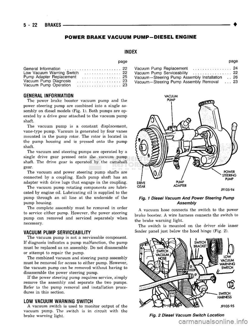
The power brake booster vacuum pump
and the
power steering pump
are
combined into
a
single
as
sembly
on
diesel models
(Fig. 1).
Both pumps
are op
erated
by a
drive gear attached
to the
vacuum pump shaft. The vacuum pump
is a
constant displacement,
vane-type pump. Vacuum
is
generated
by
four vanes
mounted
in the
pump rotor.
The
rotor
is
located
in
the pump housing
and is
pressed onto
the
pump shaft. The vacuum
and
steering pumps
are
operated
by a
single drive gear pressed onto
the
vacuum pump
shaft.
The
drive gear
is
operated
by the
camshaft
gear. The vacuum
and
power steering pump shafts
are
connected
by a
coupling. Each pump shaft
has an
adapter with drive lugs that engage
in the
coupling. The vacuum pump rotating components
are
lubri
cated
by
engine
oil.
Lubricating
oil is
supplied
to the
pump through
an oil
line
at the
underside
of the
pump housing. The complete assembly must
be
removed
in
order
to service either pump. However,
the
power steering
pump
can
removed
and
serviced separately when necessary.
VACUUM
PUMP
SERVICEABILITY
The vacuum pump
is not a
serviceable component.
If diagnosis indicates
a
pump malfunction,
the
pump must
be
replaced
as an
assembly.
Do not
disassemble
or attempt
to
repair
the
pump.
The combined vacuum
and
steering pump assembly
must
be
removed
for
access
to
either pump. However,
the vacuum pump
can be
removed without having
to
disassemble
the
power steering pump. If
the
power steering pump requires service, simply
remove
the
assembly
and
separate
the two
pumps. Refer
to the
pump removal
and
installation procedures
in
this section.
LOW
VACUUM
WARNING
SWITCH
A vacuum switch
is
used
to
monitor output
of the
vacuum pump.
The
switch
is in
circuit with
the
brake warning light.
VACUUM
PUMP
DRIVE
GEAR
PUMP
ADAPTER
POWER
STEERING
PUMP
J9105-94
Fig.
1
Diesel
Vacuum
And
Power
Steering
Pump
Assembly
A vacuum hose connects
the
switch
to the
power
brake booster.
A
wire harness connects
the
switch
to
the brake warning light.
The switch
is
mounted
on the
driver side inner
fender panel just below
the
hood hinge
(Fig. 2),
b
LOW
VACUUM
WARNING
SWITCH
SWITCH
HARNESS
J9105-95
Fig.
2
Diesel
Vacuum
Switch
Location
Page 255 of 1502
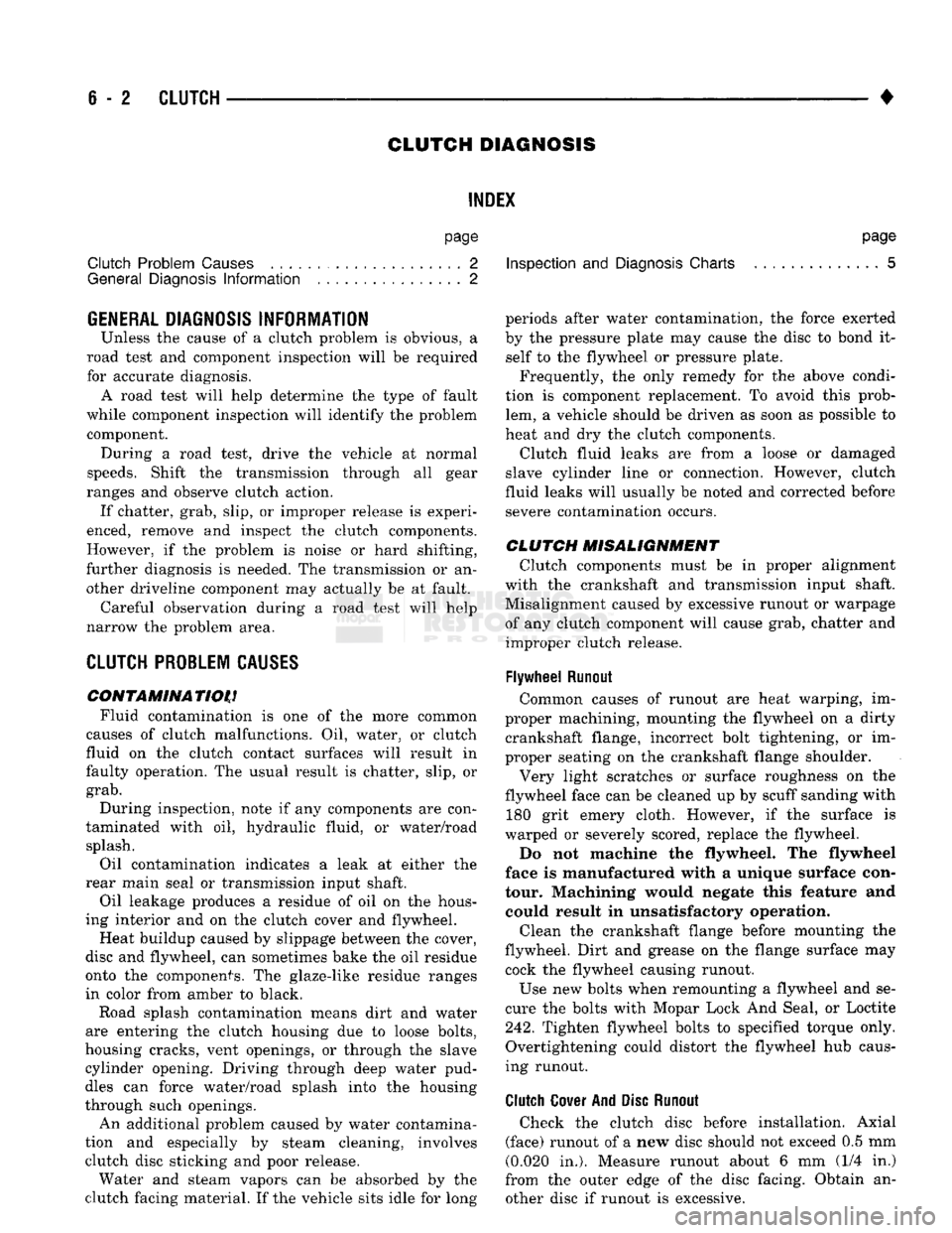
6
- 2
CLUTCH
•
CLUTCH DIAGNOSIS
INDEX
page
Clutch Problem
Causes
, 2
General
Diagnosis
Information
2
GENERAL
DIAGNOSIS INFORMATION
Unless the cause of a clutch problem is obvious, a
road test and component inspection will be required
for accurate diagnosis. A road test will help determine the type of fault
while component inspection will identify the problem component. During a road test, drive the vehicle at normal
speeds. Shift the transmission through all gear
ranges and observe clutch action. If chatter, grab, slip, or improper release is experi
enced, remove and inspect the clutch components.
However, if the problem is noise or hard shifting,
further diagnosis is needed. The transmission or an
other driveline component may actually be at fault. Careful observation during a road test will help
narrow the problem area.
CLUTCH PROBLEM
CAUSES
CONTAMINATION Fluid contamination is one of the more common
causes of clutch malfunctions. Oil, water, or clutch
fluid on the clutch contact surfaces will result in
faulty operation. The usual result is chatter, slip, or
grab.
During inspection, note if any components are con
taminated with oil, hydraulic fluid, or water/road splash.
Oil contamination indicates a leak at either the
rear main seal or transmission input shaft.
Oil leakage produces a residue of oil on the hous
ing interior and on the clutch cover and flywheel.
Heat buildup caused by slippage between the cover,
disc and flywheel, can sometimes bake the oil residue
onto the components. The glaze-like residue ranges
in color from amber to black.
Road splash contamination means dirt and water
are entering the clutch housing due to loose bolts,
housing cracks, vent openings, or through the slave
cylinder opening. Driving through deep water pud
dles can force water/road splash into the housing
through such openings.
An additional problem caused by water contamina
tion and especially by steam cleaning, involves
clutch disc sticking and poor release. Water and steam vapors can be absorbed by the
clutch facing material. If the vehicle sits idle for long
page
Inspection
and
Diagnosis
Charts 5
periods after water contamination, the force exerted
by the pressure plate may cause the disc to bond it self to the flywheel or pressure plate.
Frequently, the only remedy for the above condi
tion is component replacement. To avoid this prob
lem, a vehicle should be driven as soon as possible to
heat and dry the clutch components.
Clutch fluid leaks are from a loose or damaged
slave cylinder line or connection. However, clutch
fluid leaks will usually be noted and corrected before severe contamination occurs.
CLUTCH MISALIGNMENT
Clutch components must be in proper alignment
with the crankshaft and transmission input shaft.
Misalignment caused by excessive runout or warpage of any clutch component will cause grab, chatter and improper clutch release.
Flywheel
Runout
Common causes of runout are heat warping, im
proper machining, mounting the flywheel on a dirty crankshaft flange, incorrect bolt tightening, or im
proper seating on the crankshaft flange shoulder.
Very light scratches or surface roughness on the
flywheel face can be cleaned up by scuff sanding with 180 grit emery cloth. However, if the surface is
warped or severely scored, replace the flywheel.
Do not machine the flywheel. The flywheel
face is manufactured with a unique surface con
tour. Machining would negate this feature and could result in unsatisfactory operation.
Clean the crankshaft flange before mounting the
flywheel. Dirt and grease on the flange surface may cock the flywheel causing runout.
Use new bolts when remounting a flywheel and se
cure the bolts with Mopar Lock And Seal, or Loctite
242.
Tighten flywheel bolts to specified torque only.
Overtightening could distort the flywheel hub caus
ing runout.
Clutch
Cover
And Disc
Runout
Check the clutch disc before installation. Axial
(face) runout of a new disc should not exceed 0.5 mm
(0.020 in.). Measure runout about 6 mm (1/4 in.)
from the outer edge of the disc facing. Obtain an other disc if runout is excessive.
Page 262 of 1502
•
CLUTCH
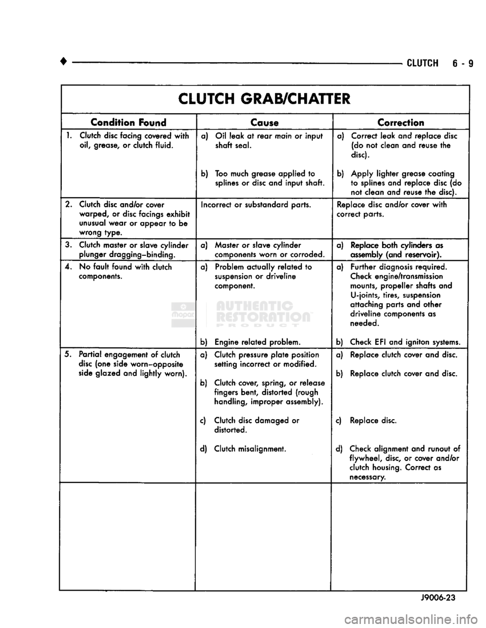
6 - 9 CLUTCH GRAB/CHATTER
Condition
Found
Cause
T
Correction
1.
Clutch
disc
facing covered
with
oil, grease, or clutch fluid. a) Oil leak at
rear
main or input
shaft seal.
b) Too much grease applied to
splines
or
disc
and input shaft. a) Correct leak and replace
disc
(do not clean and reuse the
disc).
b) Apply lighter grease coating to splines and replace
disc
(do not clean and reuse the disc).
2. Clutch
disc
and/or cover warped, or
disc
facings
exhibit
unusual
wear or appear to be
wrong type. Incorrect or substandard parts.
Replace
disc
and/or cover
with
correct parts.
3. Clutch master or slave cylinder plunger dragging-binding. a) Master or slave cylinder
components worn or corroded. a) Replace both cylinders as
assembly
(and reservoir).
4. No
fault
found
with
clutch
components.
a) Problem actually
related
to
suspension
or driveline
component.
b) Engine
related
problem. a)
Further
diagnosis
required.
Check
engine/transmission
mounts,
propeller shafts and U-joints, tires,
suspension
attaching parts and other
driveline components as needed.
b) Check EFI and igniton
systems.
5.
Partial
engagement of clutch
disc
(one side worn-opposite
side
glazed and lightly worn). a) Clutch pressure
plate
position
setting incorrect or modified.
b) Clutch cover, spring, or release fingers bent, distorted (rough
handling,
improper assembly).
c) Clutch
disc
damaged or distorted.
d) Clutch misalignment. a) Replace clutch cover and
disc.
b) Replace clutch cover and
disc.
c) Replace
disc.
d) Check alignment and runout of flywheel,
disc,
or cover and/or clutch
housing.
Correct as
necessary.
J9006-23