radiator DODGE TRUCK 1993 Service User Guide
[x] Cancel search | Manufacturer: DODGE, Model Year: 1993, Model line: TRUCK, Model: DODGE TRUCK 1993Pages: 1502, PDF Size: 80.97 MB
Page 283 of 1502
7
- 12
COOLING
SYSTEM
• DIESEL COOLING SYSTEM DIAGNOSIS-CONTINUED
CONDITION
AND
CHECKS
DIAGNOSIS
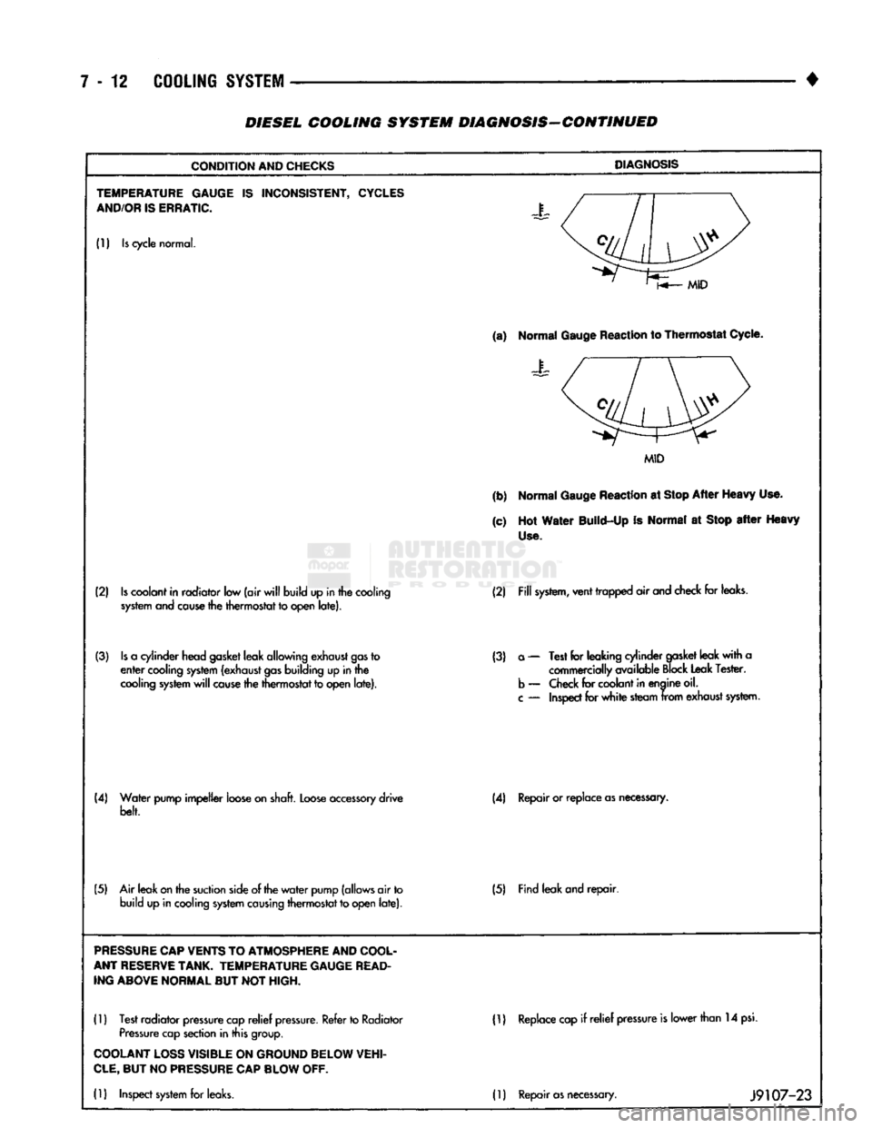
TEMPERATURE GAUGE
IS
INCONSISTENT,
CYCLES
AND/OR
IS
ERRATIC.
J
(1)
Is
cycle
normal.
(a)
Normal
Gauge
Reaction
to Thermostat
Cycle.
Normal
Gauge
Reaction
to Thermostat
Cycle.
MID
(b)
Normal
Gauge
Reaction
at
Stop
After
Heavy
Use.
(c)
Hot
Water
Build-Up
Is
Normal
at
Stop
after
Heavy
Use.
(2)
Is
coolant
in
radiator
low
(air
will
build
up in
the
cooling
system and cause
the
thermostat
to
open
late). (2)
Fill
system,
vent
trapped
air
and
check
for
leaks.
(3)
Is
a
cylinder
head
gasket
leak
allowing
exhaust
gas
to
enter
cooling
system
(exhaust
gas
building
up in
the
cooling
system
will
cause
the
thermostat
to
open
late).
(3)
a
—
Test
for
leaking
cylinder
gasket
leak
with
a
commercially
available
Block
Leak
Tester,
b
—
Check
for
coolant
in
enaine
oil.
c
—
Inspect
for
white
steam
from
exhaust
system.
(4)
Water
pump
impeller
loose
on
shaft.
Loose
accessory
drive
belt. (4)
Repair or
replace
as
necessary.
(5)
Air
leak
on
the
suction
side
of the
water
pump
(allows
air
to
build
up in
cooling
system causing
thermostat
to
open
late). (5)
Find
leak
and
repair.
PRESSURE
CAP
VENTS
TO
ATMOSPHERE
AND
COOL
ANT
RESERVE
TANK.
TEMPERATURE GAUGE
READ
ING ABOVE NORMAL
BUT NOT
HIGH.
(1)
Test
radiator
pressure
cap
relief
pressure.
Refer
to
Radiator
Pressure
cap
section
in
this
group.
ID
Replace
cap
if relief
pressure
is
lower
than
14
psi.
COOLANT
LOSS
VISIBLE
ON
GROUND BELOW VEHI
CLE,
BUT NO
PRESSURE
CAP
BLOW
OFF.
(1)
Inspect
system
for
leaks.
(1)
Repair
as
necessary.
J9107-23
Page 284 of 1502
•
COOLING SYSTEM 7-13
DIESEL COOLING SYSTEM DIAGNOSIS-CONTINUED
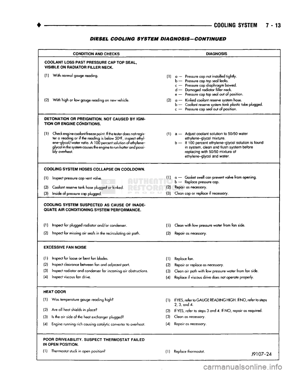
CONDITION
AND
CHECKS
DIAGNOSIS
COOLANT
LOSS
PAST
PRESSURE
CAP
TOP
SEAL,
VISIBLE
ON
RADIATOR
FILLER
NECK.
(1)
With
normal gauge reading. (1) a — Pressure cap not installed
tightly.
b — Pressure cap top seal leaks.
c
— Pressure cap diaphragm bowed.
d
— Damaged
radiator
filler
neck.
e — Pressure cap top seal out of position.
(2)
With
high or low gauge reading on new vehicle. (2) a — Kinked coolant reserve system hose.
(2)
With
high or low gauge reading on new vehicle.
b — Coolant reserve system
tank
plastic
tube
plugged.
c
— Pressure cap seal out of position.
DETONATION
OR
PREIGNITION.
NOT
CAUSED
BY
IGNI
TION OR
ENGINE
CONDITIONS.
(1)
Check engine coolant
freeze
point.
If the
tester
does
not
regis
(1) a — Adjust coolant solution to
50/50
water
ter a reading or if the reading is below 50°F, inspect
ethyl
ethylene-glycol
mixture.
ene-glycol/
water
ratio.
A 100
percent
solution of
ethylene-
b — If 100
percent
ethylene-glycol
solution is found
glycol
in
the
system
causes
the engine
to
run
hotter
and
possi
in system,
clean
and flush system
before
bly overheat.
replacing
with
50/50
mixture
of
ethylene-glycol
and
water.
COOLING
SYSTEM
HOSES
COLLAPSE
ON
COOLDOWN.
(1) Inspect pressure cap
vent
valve. (1) a — Gasket swell can
prevent
valve
from
opening.
b — Replace pressure cap.
(2) Coolant reserve
tank
hose plugged or kinked. (2) Repair as necessary.
(3) Inside of pressure cap plugged. (3) Clean cap or
replace
if necessary.
COOLING
SYSTEM
SUSPECTED
AS
CAUSE
OF
INADE
QUATE
AIR CONDITIONING
SYSTEM
PERFORMANCE.
(1) Inspect for plugged
radiator
and/or condenser. (D Clean
with
low pressure
water
from
fan side.
(2) Inspect for
missing
air
seals
in the
recirculating
air path. (2) Repair
as
necessary.
EXCESSIVE
FAN
NOISE
(1)
Inspect for loose or
bent
fan blades. (1) Replace fan.
(2) Inspect clearance
between
fan and
adjacent
part.
(2) Repair or
replace
as necessary.
(3) Inspect
radiator
and condenser for incoming air obstructions. (3) Clean air path
with
low pressure
water
from
fan side.
(4) Inspect
viscous
fan drive. (4) Replace if
viscous
drive
does not
operate
properly.
HEAT
ODOR
(1)
Was
temperature
gauge reading high? (1) If
YES,
refer
to
GAUGE
READING
HIGH.
If
NO,
refer
to
steps
2, 3, and 4.
(2) Are all
heat
shields in place? (2) If
YES,
refer
to steps 3 and 4. If NO,
repair
as
required.
(3)
Is
the air side of the
heat
exchanger plugged? (3) Clean as necessary.
(4) Engine running rich causing
catalytic
converter
to overheat. (4) Repair
as
necessary.
POOR
DRIVEABILITY.
SUSPECT
THERMOSTAT FAILED
IN OPEN POSITION.
(1)
Thermostat stuck in open position? 01 Replace thermostat. ._ _0 .
Jy
107-24
Page 286 of 1502
•
COOLING SYSTEM
7 - 15
SERVICE
PROCEDURES
INDEX
page
Coolant
26
Coolant Reserve/Overflow System
30
Cooling System Cleaning/Reverse Flushing
28
Cooling System Fan—Diesel Engine
. 37
Cooling System
Fan—Gas
Engines
36
Cooling System
Hoses
34
Draining Cooling System
27
Pressure
Testing
Radiator
Caps
............. 32
Radiator Pressure
Cap 31
Radiators
32
Refilling
the
Cooling System
28
WATER PUMPS—EXCEPT DIESEL
A centrifugal water pump circulates coolant
through the water jackets, passages, intake manifold,
radiator core, cooling system hoses and heater core.
The pump is driven from the engine crankshaft by a drive belt. The water pump impeller is pressed onto the rear
of a shaft that rotates in a bearing pressed into the
water pump body. The body has a small hole for ven
tilation. The water pump seals are lubricated by an
tifreeze in the coolant mixture. Additional lubrication is not necessary. A quick test to determine if pump is working is to
check if heater warms properly. A defective water
pump will not be able to circulate heated coolant
through the long heater hose to the heater core. The water pump on all models can be removed
without discharging the air conditioning system (if equipped).
REMOVAL The water pump on all gas powered engines is
bolted directly to the engine timing chain case/cover.
A gasket is used as a seal between the water pump
and timing chain case/cover.
If water pump is replaced because of bearing/shaft
damage or leaking shaft seal, the mechanical cooling
fan assembly should also be inspected. Inspect for fa tigue cracks, loose blades or loose rivets that could
have resulted from excessive vibration. Replace fan if any of these conditions are found. Also check condi
tion of the thermal viscous fan drive. Refer to Vis
cous Fan Drive in this group. (1) Disconnect negative battery cable from battery.
(2) Drain cooling system. Refer to Draining Cool
ing System in this group. Do not waste reusable coolant. If solution is clean,
drain coolant into a clean container for reuse.
(3)
Disconnect throttle cable from clip at top of fan
shroud.
page
Testing
Cooling System
for
Leaks
. 29
Thermostat
22
Transmission
Oil
Cooler—Diesel
35
Transmission
Oil
Cooler—Except Diesel
35
Transmission Oil-To-Air Cooler
36
Viscous
Fan
Drive
38
Water
Pump
Bypass
Hose—All
Gas
Powered
Engines
.............................. 19
Water
Pumps—5.9L Diesel
18
Water
Pumps—Except Diesel
15
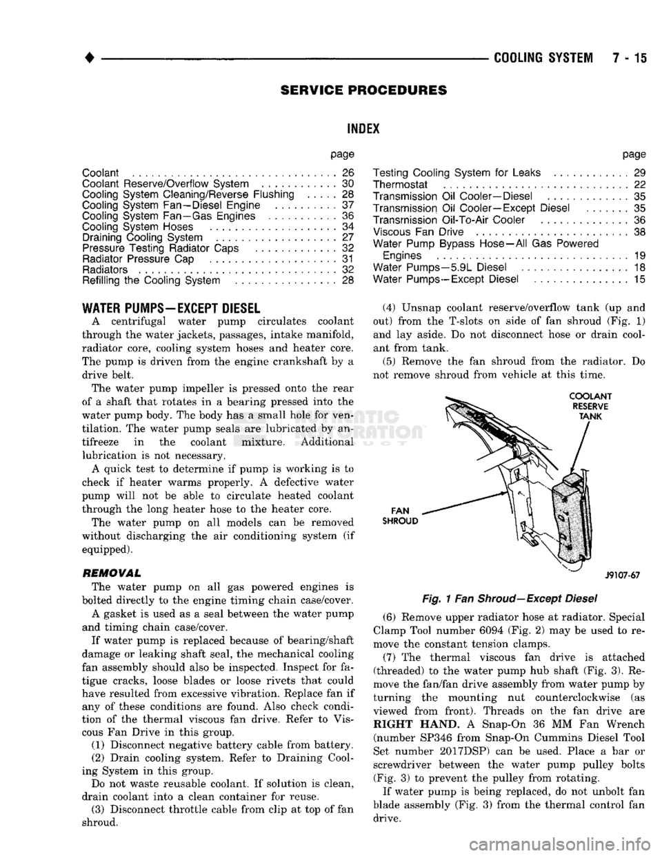
(4) Unsnap coolant reserve/overflow tank (up and
out) from the T-slots on side of fan shroud (Fig. 1) and lay aside. Do not disconnect hose or drain cool
ant from tank.
(5) Remove the fan shroud from the radiator. Do
not remove shroud from vehicle at this time.
FAN
SHROUD
J9107-67
Fig.
1 Fan
Shroud—Except
Diesel
(6) Remove upper radiator hose at radiator. Special
Clamp Tool number 6094 (Fig. 2) may be used to re
move the constant tension clamps.
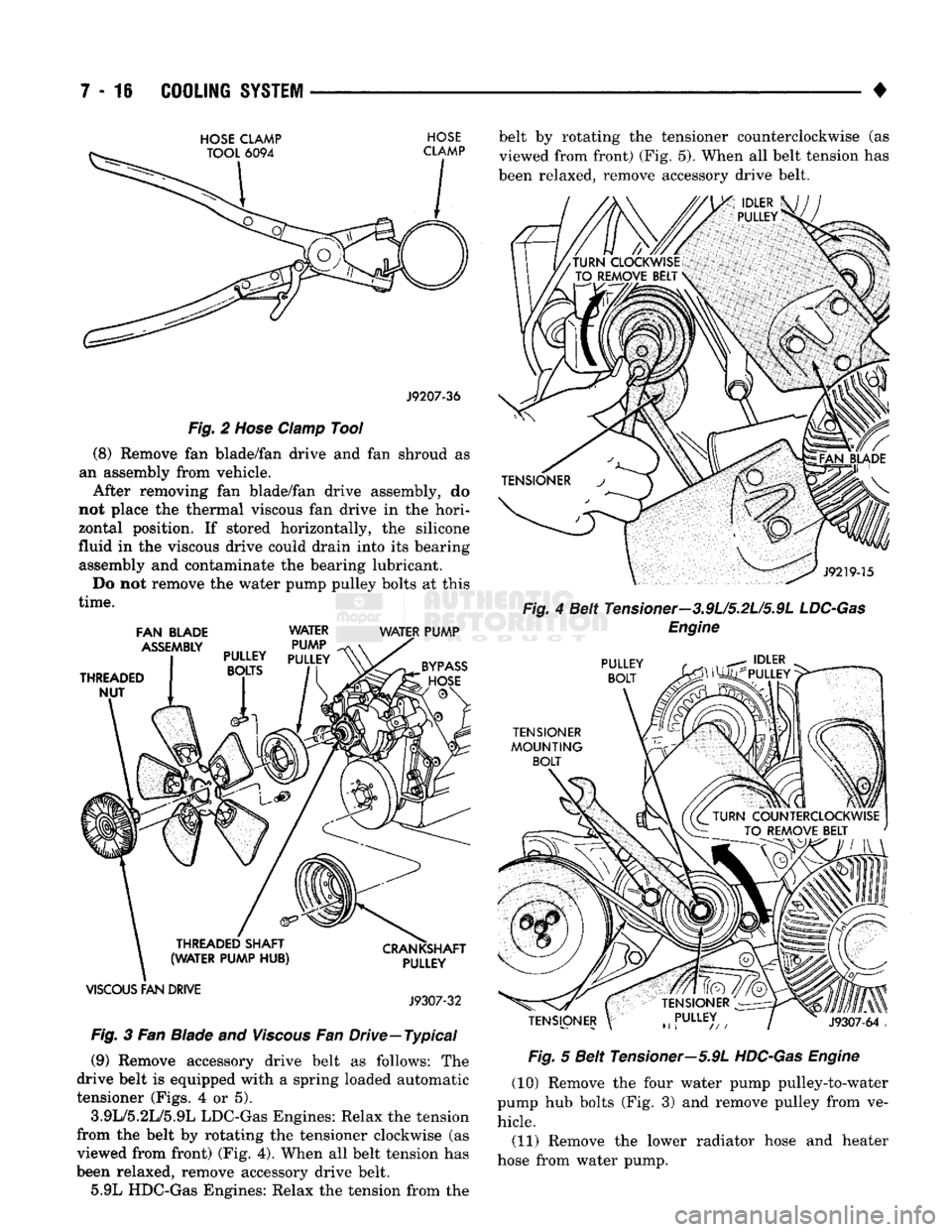
(7) The thermal viscous fan drive is attached
(threaded) to the water pump hub shaft (Fig. 3). Re
move the fan/fan drive assembly from water pump by
turning the mounting nut counterclockwise (as viewed from front). Threads on the fan drive are RIGHT HAND. A Snap-On 36 MM Fan Wrench (number SP346 from Snap-On Cummins Diesel Tool
Set number 2017DSP) can be used. Place a bar or
screwdriver between the water pump pulley bolts (Fig. 3) to prevent the pulley from rotating.
If water pump is being replaced, do not unbolt fan
blade assembly (Fig. 3) from the thermal control fan drive.
Page 287 of 1502
7 - 16
COOLING
SYSTEM
•
HOSE
CLAMP
HOSE
J9207-36
Fig.
2
Hose
Clamp
Tool
(8) Remove fan blade/fan drive and fan shroud as
an assembly from vehicle. After removing fan blade/fan drive assembly, do
not place the thermal viscous fan drive in the hori
zontal position. If stored horizontally, the silicone
fluid in the viscous drive could drain into its bearing assembly and contaminate the bearing lubricant.
Do not remove the water pump pulley bolts at this
time.
FAN
BLADE
WATER WATER
PUMP
VISCOUS
FAN
DRIVE
J9307-32
Fig.
3 Fan Blade and
Viscous
Fan Drive—Typical (9) Remove accessory drive belt as follows: The
drive belt is equipped with a spring loaded automatic
tensioner (Figs. 4 or 5).
3.9L/5.2L/5.9L LDC-Gas Engines: Relax the tension
from the belt by rotating the tensioner clockwise (as
viewed from front) (Fig. 4). When all belt tension has
been relaxed, remove accessory drive belt. 5.9L HDC-Gas Engines: Relax the tension from the belt by rotating the tensioner counterclockwise (as
viewed from front) (Fig. 5). When all belt tension has
been relaxed, remove accessory drive belt.
Fig.
4 Belt Tensioner—3.9L/5.2L/5.9L
LDC-Gas
Engine
Fig.
5 Belt Tensioner—5.9L
HDC-Gas
Engine
(10) Remove the four water pump pulley-to-water
pump hub bolts (Fig. 3) and remove pulley from ve hicle.
(11) Remove the lower radiator hose and heater
hose from water pump.
Page 288 of 1502
•
COOLING
SYSTEM
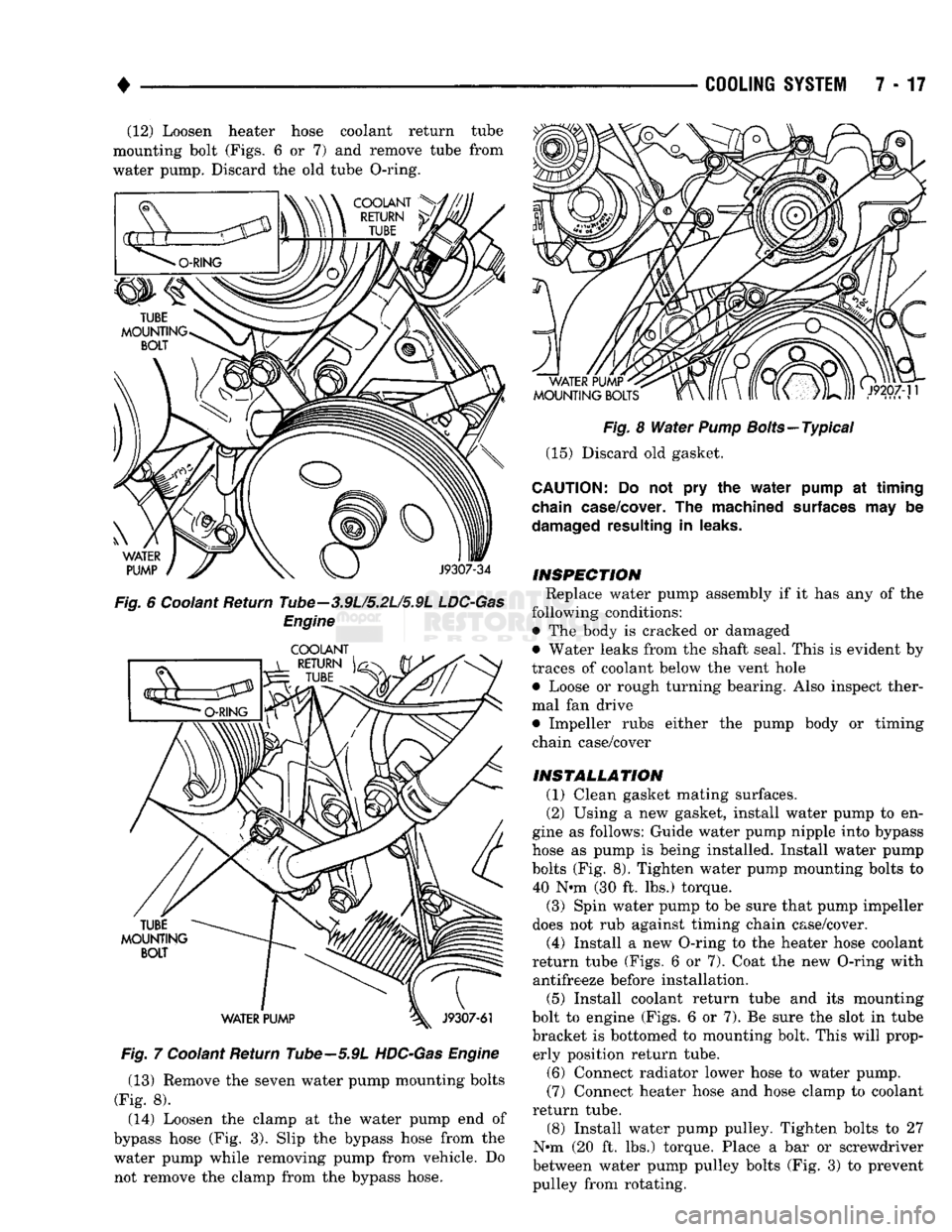
7-17 (12) Loosen heater hose coolant return tube
mounting bolt (Figs. 6 or 7) and remove tube from
water pump. Discard the old tube O-ring.
Fig.
6 Coolant Return Tube—3.9L/5.2L/5.9L
LDC-Gas
Engine
Fig.
7 Coolant Return Tube—5.9L
HDC-Gas
Engine
(13) Remove the seven water pump mounting bolts
(Fig. 8). (14) Loosen the clamp at the water pump end of
bypass hose (Fig. 3). Slip the bypass hose from the water pump while removing pump from vehicle. Do not remove the clamp from the bypass hose.
Fig.
8
Water
Pump
Bolts—Typical
(15) Discard old gasket.
CAUTION:
Do not pry the
water
pump
at timing
chain
case/cover.
The machined
surfaces
may be
damaged
resulting in
leaks.
INSPECTION
Replace water pump assembly if it has any of the
following conditions: • The body is cracked or damaged
• Water leaks from the shaft seal. This is evident by
traces of coolant below the vent hole • Loose or rough turning bearing. Also inspect thermal fan drive
• Impeller rubs either the pump body or timing
chain case/cover
INSTALLATION
(1) Clean gasket mating surfaces. (2) Using a new gasket, install water pump to en
gine as follows: Guide water pump nipple into bypass
hose as pump is being installed. Install water pump bolts (Fig. 8). Tighten water pump mounting bolts to 40 N-m (30 ft. lbs.) torque.
(3) Spin water pump to be sure that pump impeller
does not rub against timing chain case/cover.
(4) Install a new O-ring to the heater hose coolant
return tube (Figs. 6 or 7). Coat the new O-ring with antifreeze before installation.
(5) Install coolant return tube and its mounting
bolt to engine (Figs. 6 or 7). Be sure the slot in tube bracket is bottomed to mounting bolt. This will prop erly position return tube.
(6) Connect radiator lower hose to water pump.
(7) Connect heater hose and hose clamp to coolant
return tube.
(8) Install water pump pulley. Tighten bolts to 27
N*m (20 ft. lbs.) torque. Place a bar or screwdriver
between water pump pulley bolts (Fig. 3) to prevent pulley from rotating.
Page 289 of 1502
7 - 18
COOLING
SYSTEM
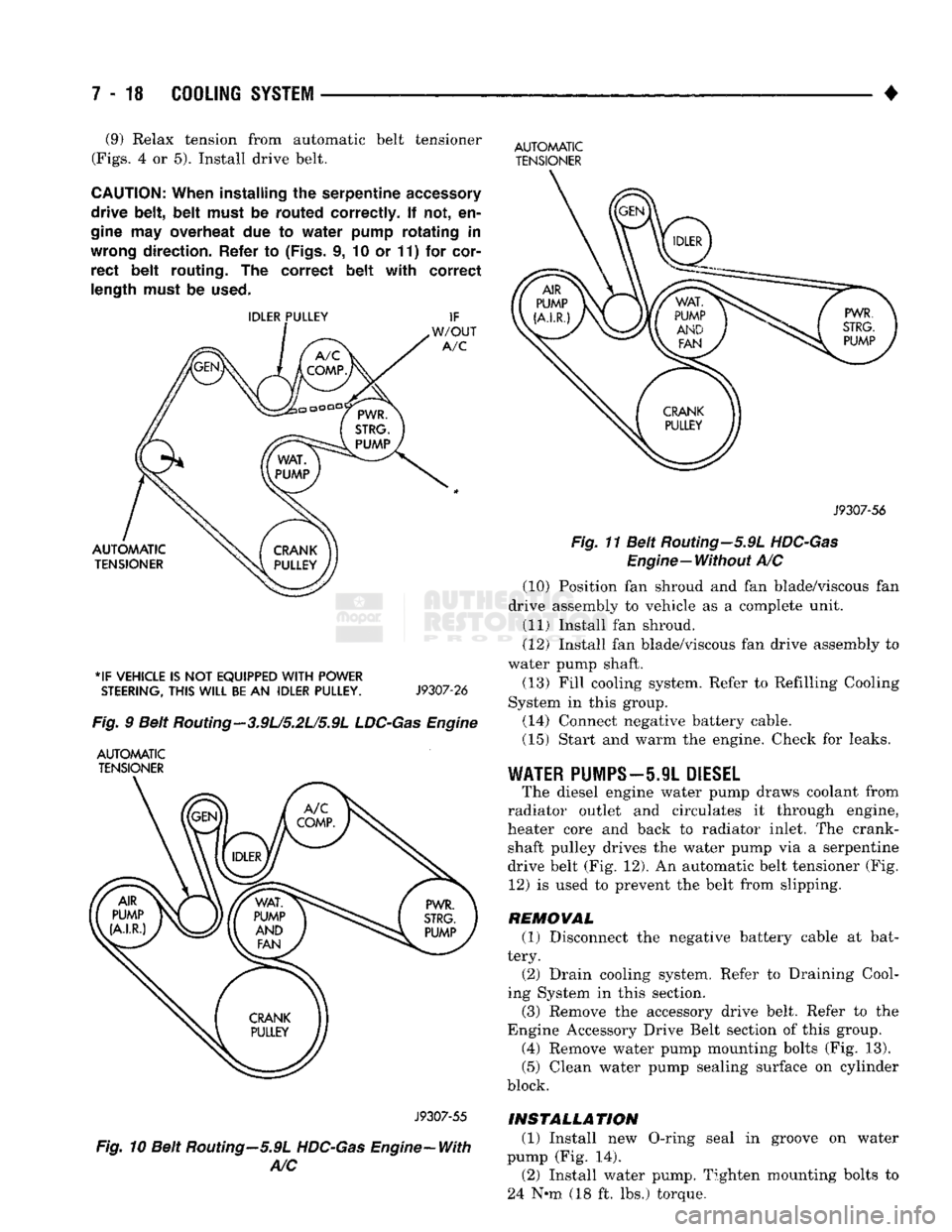
• (9) Relax tension from automatic belt tensioner
(Figs.
4 or 5). Install drive belt.
CAUTION:
When
installing
the
serpentine
accessory
drive
belt, belt
must
be
routed
correctly.
If not, en
gine
may
overheat
due to
water
pump
rotating
in
wrong
direction.
Refer
to
(Figs,
i, 10 or 11) for
cor
rect
belt
routing.
The
correct
belt with
correct
length
must
be
used.
*IF
VEHICLE
IS NOT
EQUIPPED
WITH
POWER
STEERING,
THIS
WILL
BE
AN
IDLER
PULLEY.
J9307-26
Fig.
9 Belt Routing—3.9U5.2L/5.9L
LDC-Gas
Engine
AUTOMATIC
TENSIONER
AUTOMATIC
TENSIONER
J9307-56
Fig.
11 Belt Routing—5.9L
HDC-Gas
Engine—Without
A/C (10) Position fan shroud and fan blade/viscous fan
drive assembly to vehicle as a complete unit. (11) Install fan shroud.
(12) Install fan blade/viscous fan drive assembly to
water pump shaft.
(13) Fill cooling system. Refer to Refilling Cooling
System in this group. (14) Connect negative battery cable.
(15) Start and warm the engine. Check for leaks.
WATER
PUMPS—5.9L
DIESEL
The diesel engine water pump draws coolant from
radiator outlet and circulates it through engine,
heater core and back to radiator inlet. The crank shaft pulley drives the water pump via a serpentine
drive belt (Fig. 12). An automatic belt tensioner (Fig. 12) is used to prevent the belt from slipping.
REMOVAL (1) Disconnect the negative battery cable at bat
tery. (2) Drain cooling system. Refer to Draining Cool
ing System in this section.
(3) Remove the accessory drive belt. Refer to the
Engine Accessory Drive Belt section of this group. (4) Remove water pump mounting bolts (Fig. 13).
(5) Clean water pump sealing surface on cylinder
block.
J9307-55
Fig.
10 Belt Routing—5.9L
HDC-Gas
Engine-With
A/C
INSTALLATION
(1) Install new O-ring seal in groove on water
pump (Fig. 14). (2) Install water pump. Tighten mounting bolts to
24 N-m (18 ft. lbs.) torque.
Page 291 of 1502
7 - 20
COOLING
SYSTEM
•
HOSE
CLAMP
HOSE
J9207-36
Fig.
16
Hose
Clamp
Tool
WITH AIR
CONDITIONING
(A/C)
REMOVAL
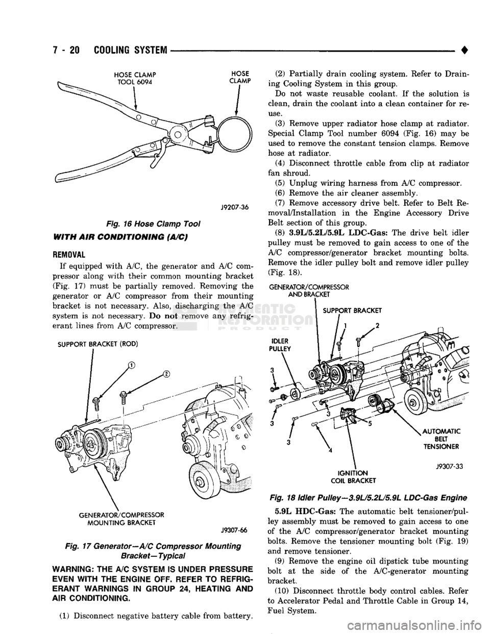
If equipped with A/C, the generator and A/C com
pressor along with their common mounting bracket (Fig. 17) must be partially removed. Removing the
generator or A/C compressor from their mounting
bracket is not necessary. Also, discharging the A/C system is not necessary. Do not remove any refrig
erant lines from A/C compressor.
SUPPORT BRACKET (ROD)
GENERATOR/COMPRESSOR
MOUNTING
BRACKET
J9307-66
Fig.
17 Generator—A/C
Compressor
Mounting
Bracket—
Typical
WARNING;
THE A/C
SYSTEM
IS
UNDER
PRESSURE
EVEN
WITH
THE
ENGINE OFF. REFER
TO
REFRIG
ERANT
WARNINGS
IN
GROUP
24,
HEATING
AND
AIR
CONDITIONING.
(1) Disconnect negative battery cable from battery. (2) Partially drain cooling system. Refer to Drain
ing Cooling System in this group.
Do not waste reusable coolant. If the solution is
clean, drain the coolant into a clean container for re
use.
(3) Remove upper radiator hose clamp at radiator.
Special Clamp Tool number 6094 (Fig. 16) may be
used to remove the constant tension clamps. Remove
hose at radiator.
(4) Disconnect throttle cable from clip at radiator
fan shroud. (5) Unplug wiring harness from A/C compressor.
(6) Remove the air cleaner assembly.
(7) Remove accessory drive belt. Refer to Belt Re
moval/Installation in the Engine Accessory Drive
Belt section of this group.
(8) 3.9L/5.2L/5.9L LDC-Gas: The drive belt idler
pulley must be removed to gain access to one of the
A/C compressor/generator bracket mounting bolts. Remove the idler pulley bolt and remove idler pulley (Fig. 18).
GENERATOR/COMPRESSOR
AND
BRACKET
SUPPORT BRACKET
IGNITION
COIL
BRACKET
Fig.
18 Idler Pulley-3.9U5.2U5.9L
LDC-Gas
Engine
5.9L HDC-Gas: The automatic belt tensioner/pul-
ley assembly must be removed to gain access to one
of the A/C compressor/generator bracket mounting
bolts.
Remove the tensioner mounting bolt (Fig. 19) and remove tensioner.
(9) Remove the engine oil dipstick tube mounting
bolt at the side of the A/C-generator mounting
bracket.
(10) Disconnect throttle body control cables. Refer
to Accelerator Pedal and Throttle Cable in Group 14,
Fuel System.
Page 293 of 1502
7 - 22
COOLING
SYSTEM
•
Fig.
23 Bracket
Bolts—5.9L
HDC-Gas Engine
(2) Install bypass hose to engine.
(3) Secure both hose clamps.
(4) Install generator-A/C mounting bracket assem
bly to engine. Tighten bolts (number 1 and 2 Fig. 17)
to 54 Nnn (40 ft. lbs.) torque. Tighten bracket mount ing bolts (Figs. 22 or 23) to 40 N-m (30 ft. lbs.)
torque.
(5) Install a new O-ring to the heater hose coolant
return tube (Figs. 20 or 21). Coat the new O-ring
with antifreeze before installation. (6) Install coolant return tube and its mounting
bolt to engine (Figs. 20 or 21). (7) Connect throttle body control cables.
(8) Install oil dipstick mounting bolt.
(9) 3.9L/5.2L/5.9L LDC-Gas: Install idler pulley.
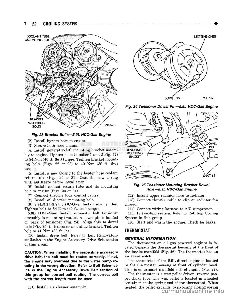
Tighten bolt to 54 Nnn (40 ft. lbs.) torque. 5.9L HDC-Gas: Install automatic belt tensioner
assembly to mounting bracket. A dowel pin is located
on back of tensioner (Fig. 24). Align this to dowel
hole (Fig. 25) in tensioner mounting bracket. Tighten
bolt to 41 N-m (30 ft. lbs.). (10) Install drive belt. Refer to Belt Removal/In
stallation in the Engine Accessory Drive Belt section
of this group.
CAUTION:
When installing
the
serpentine
accessory
drive belt,
the
belt must
be
routed correctly.
If not,
the engine
may
overheat
due to the
water pump
ro
tating
in the
wrong direction. Refer
to
Belt Schemat
ics
in the
Engine
Accessory
Drive Belt section
of
this
group
for
correct belt routing.
The
correct belt
with the
correct length must
be
used.
(11) Install air cleaner assembly.
BELT TENSIONER
DOWEL PIN
J9307-63
Fig.
24 Tensioner
Dowel
Pin—5.9L
HDC-Gas Engine Fig.
25 Tensioner
Mounting
Bracket
Dowel
Hote—5.9L
HDC-Gas Engine
(12) Install upper radiator hose to radiator.
(13) Connect throttle cable to clip at radiator fan
shroud.
(14) Connect wiring harness to A/C compressor. (15) Fill cooling system. Refer to Refilling Cooling
System in this group.
(16) Start and warm the engine. Check for leaks.
THERMOSTAT
GENERAL
INFORMATION
The thermostat on all gas powered engines is lo
cated beneath the thermostat housing at the front of
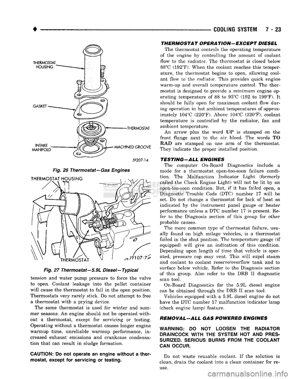
the intake manifold (Fig. 26). The thermostat has an air bleed notch.
The thermostat of the 5.9L diesel engine is located
in the thermostat housing at front of cylinder head.
This is on exhaust manifold side of engine (Fig. 27). The thermostat is a wax pellet driven, reverse pop
pet choke type. The wax pellet is located in a sealed container at the spring end of the thermostat. When
heated, the pellet expands, overcoming closing spring
Page 294 of 1502
•
COOLING SYSTEM
7 - 23
•THERMOSTAT
MACHINED GROOVE
J9207-14
Fig.
26
Thermostat—
Gas Engines
Fig.
27 Thermostat—5.9L Diesel—Typical
tension and water pump pressure to force the valve
to open. Coolant leakage into the pellet container
will cause the thermostat to fail in the open position.
Thermostats very rarely stick. Do not attempt to free a thermostat with a prying device.
The same thermostat is used for winter and sum
mer seasons. An engine should not be operated with
out a thermostat, except for servicing or testing. Operating without a thermostat causes longer engine
warmup time, unreliable warmup performance, in
creased exhaust emissions and crankcase condensa
tion that can result in sludge formation.
CAUTION:
Do not operate an engine without a
ther
mostat,
except for
servicing
or
testing.
THERMOSTAT OPERATION-EXCEPT DIESEL
The thermostat controls the operating temperature
of the engine by controlling the amount of coolant
flow to the radiator. The thermostat is closed below 88°C (192°F). When the coolant reaches this temper
ature, the thermostat begins to open, allowing cool
ant flow to the radiator. This provides quick engine
warm-up and overall temperature control. The ther
mostat is designed to provide a minimum engine op erating temperature of 88 to 93°C (192 to 199°F). It
should be fully open for maximum coolant flow dur
ing operation in hot ambient temperatures of approx
imately 104°C (220°F). Above 104°C (220°F), coolant
temperature is controlled by the radiator, fan and ambient temperature.
An arrow plus the word UP is stamped on the
front flange next to the air bleed. The words TO RAD are stamped on one arm of the thermostat.
They indicate the proper installed position.
TESTING-ALL ENGINES The computer On-Board Diagnostics include a
mode for a thermostat open-too-soon failure condi
tion. The Malfunction Indicator Light (formerly called the Check Engine Light) will not be lit by an
open-too-soon condition. But, if it has failed open, a
Diagnostic Trouble Code (DTC) number 17 will be
set. Do not change a thermostat for lack of heat as
indicated by the instrument panel gauge or heater
performance unless a DTC number 17 is present. Re
fer to the Diagnosis section of this group for other
probable causes.
The more common type of thermostat failure, usu
ally found on high milage vehicles, is a thermostat
failed in the shut position. The temperature gauge (if equipped) will give an indication of this condition.
Depending upon length of time that vehicle is oper
ated, pressure cap may vent. This will expel steam
and coolant to coolant reserve/overflow tank and to
surface below vehicle. Refer to the Diagnosis section
of this group. Also refer to the DRB II diagnostic
scan tool.
On-Board Diagnostics for the 5.9L diesel engine
can be obtained through the DRB II scan tool.
Vehicles equipped with a 5.9L diesel engine do not
have the DTC number 17 malfunction indicator lamp (check engine lamp) feature.
REMOVAL-ALL GAS POWERED ENGINES
WARNING:
DO NOT
LOOSEN
THE
RADIATOR DRAINCOCK
WITH
THE
SYSTEM
HOT AND
PRES
SURIZED.
SERIOUS BURNS FROM
THE
COOLANT
CAN
OCCUR.
Do not waste reusable coolant. If the solution is
clean, drain the coolant into a clean container for re
use.
Page 295 of 1502
7 - 24
COOLING SYSTEM
• If the thermostat is being replaced, be sure that
the replacement is the specified thermostat for the vehicle model and engine type. Factory installed thermostat housings on 3.9L/5.2L/
5.9L engines are installed on a gasket with an anti-
stick coating. This will aid in gasket removal and
clean-up.
(1) Disconnect negative battery cable at battery.
(2) Drain cooling system until coolant level is be
low thermostat. Refer to Draining Cooling System in
this group. If not equipped with air conditioning, pro ceed to step number 4.
(3) If equipped with air conditioning: (a) Remove the support bracket (rod) located
near the rear of generator (Fig. 28).
Fig.
28
Support
Bracket—Generator
Mounting
Bracket-to-intake
Manifold—
Typical
(b) The drive belt must be removed. Refer to Belt
Removal/Installation in the Engine Accessory
Drive Belt section of this group.
(c) The generator must be partially removed. Re
move the two generator mounting bolts. Do not re
move any wiring at generator. If equipped with
4WD,
unplug the 4WD indicator lamp wiring har
ness (located near rear of generator).
(d) Remove generator. Position generator to gain
access for thermostat gasket removal.
(4) Remove upper radiator hose clamp. Special
Clamp Tool number 6094 (Fig. 29) may be used to re
move the constant tension clamps. Remove upper ra
diator hose at thermostat housing.
(5) Position the wiring harness (behind the ther
mostat housing) to gain access to thermostat hous ing.
(6) Remove thermostat housing mounting bolts,
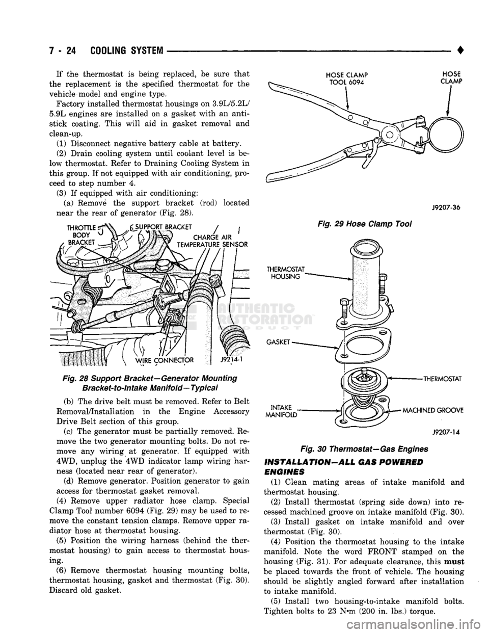
thermostat housing, gasket and thermostat (Fig. 30). Discard old gasket.
HOSE CLAMP HOSE
J9207-36
Fig.
29
Hose
Clamp
Tool
•THERMOSTAT
MACHINED GROOVE
J9207-14
Fig.
30 Thermostat—Gas
Engines
INSTALLATION-ALL GAS
POWERED
ENGINES
(1) Clean mating areas of intake manifold and
thermostat housing. (2) Install thermostat (spring side down) into re
cessed machined groove on intake manifold (Fig. 30).
(3) Install gasket on intake manifold and over
thermostat (Fig. 30).
(4) Position the thermostat housing to the intake
manifold. Note the word FRONT stamped on the
housing (Fig. 31). For adequate clearance, this must
be placed towards the front of vehicle. The housing should be slightly angled forward after installation
to intake manifold.
(5) Install two housing-to-intake manifold bolts.
Tighten bolts to 23 N-m (200 in. lbs.) torque.