air condition DODGE TRUCK 1993 Service Owner's Manual
[x] Cancel search | Manufacturer: DODGE, Model Year: 1993, Model line: TRUCK, Model: DODGE TRUCK 1993Pages: 1502, PDF Size: 80.97 MB
Page 200 of 1502
•
BRAKES
5 - 13
COMBINATION VALVE OPERATION
METERING (HOLD-OFF) VALVE The metering valve is used to balance brake action
between the front disc and rear drum brakes. The
valve meters (holds-off) full apply pressure to the front disc brakes until the rear brakeshoes are in full
contact with the drums.
The valve is designed to maintain front brake fluid
pressure at 3-30 psi until the hold-off limit of 117 psi is reached. At this point, the metering valve opens completely permitting full fluid apply pressure to the
front disc brakes.
PRESSURE DIFFERENTIAL SWITCH AND VALVE The pressure differential switch is connected to the
brake warning light. The switch is triggered by movement of the switch valve. The purpose of the switch is to monitor fluid pressure in the separate
front/rear brake hydraulic circuits.
A decrease or loss of fluid pressure in either hy
draulic circuit will cause the switch valve to shuttle
forward or rearward in response to a pressure differ ential.
Movement of the switch valve will push the switch
plunger upward. This closes the switch internal con tacts completing the electrical circuit to the warning light. The switch valve will remain in an actuated
position until repair restores system pressures to nor mal levels.
COMBINATION VALVE TESTING
TESTING METERING VALVE Metering valve operation can be checked visually
and with the aid of a helper.
Observe the metering valve stem while a helper
applies and releases the brakes. If the valve is oper
ating correctly, the stem will extend slightly when
the brakes are applied and retract when the brakes are released.
If the valve is faulty, replace the entire combina
tion valve as an assembly.
TESTING PRESSURE DIFFERENTIAL SWITCH (1) Have helper sit in drivers seat to observe brake
warning light and to operate brake pedal.
(2) Raise vehicle on hoist.
(3) Connect bleed hose to left or right rear wheel
cylinder. Then immerse hose end in glass jar par
tially filled with brake fluid.
(4) Have helper press and hold brake pedal all the
way down and observe warning light.
(a) If warning light illuminates, switch is operat
ing correctly. (b) If light fails to illuminate, check circuit fuse,
bulb and wiring. Repair as necessary and repeat test steps (3) and (4). (5) If warning light still fails to illuminate, check
brakelight and park brake switches (and wiring) with test lamp. Repair or replace parts as necessary and test differential pressure switch operation again.
(6) If warning light still does not illuminate,
switch is faulty. Replace combination valve, bleed
brakes and verify proper switch and valve operation.
COMBINATION VALVE REMOVAL/INSTALLATION
VALVE REMOVAL (1) Raise vehicle on hoist.
(2) Mark or tag brake lines connected to valve for
assembly reference.
(3) Disconnect lines at valve (Fig. 8).
(4) Disconnect wires from differential pressure
switch.
(5) Remove bolts attaching valve to frame bracket
and remove valve.
VALVE INSTALLATION (1) Mount new valve on bracket and tighten valve
and bracket screws/nuts securely.
(2) Connect brakelines to valve. Tighten fittings to
16 N*m (145 in. lbs.)
(3) Connect wires to pressure differential switch
terminal. (4) Bleed brakes.
(5) Lower vehicle and verify proper brake opera
tion.
BRAKE
LINES AND
HOSES
BRAKE LINE AND HOSE INSPECTION Flexible rubber hose is used at both front brakes
and at the rear axle junction block. Inspect the hoses
whenever the brake system is serviced, at every en gine oil change, or whenever the vehicle is in for ser
vice.
Inspect the hoses for surface cracking, scuffing, or
worn spots. Replace any brake hose immediately if
the fabric casing of the hose is exposed by cracks or abrasion.
Also check brake hose installation. Faulty installa
tion can result in kinked, twisted hoses, or contact with the wheels and tires or other chassis compo
nents.
All of these conditions can lead to scuffing,
cracking and eventual failure.
The steel brake lines should be inspected periodi
cally for evidence of corrosion, twists, kinks, leaks, or
other damage. Heavily corroded lines will eventually
rust through causing leaks. In any case, corroded or damaged brake lines should be replaced.
Page 229 of 1502
5
- 42
BRAKES
•
CALIPER
DISASSEMBLY.
(1) Drain old fluid out of caliper.
(2) Pad outboard shoe side of caliper interior with
a minimum 2.54 cm (1 in.) thickness of shop towels
(Fig. 13). Towels will prevent piston damage when it
comes out of bore.
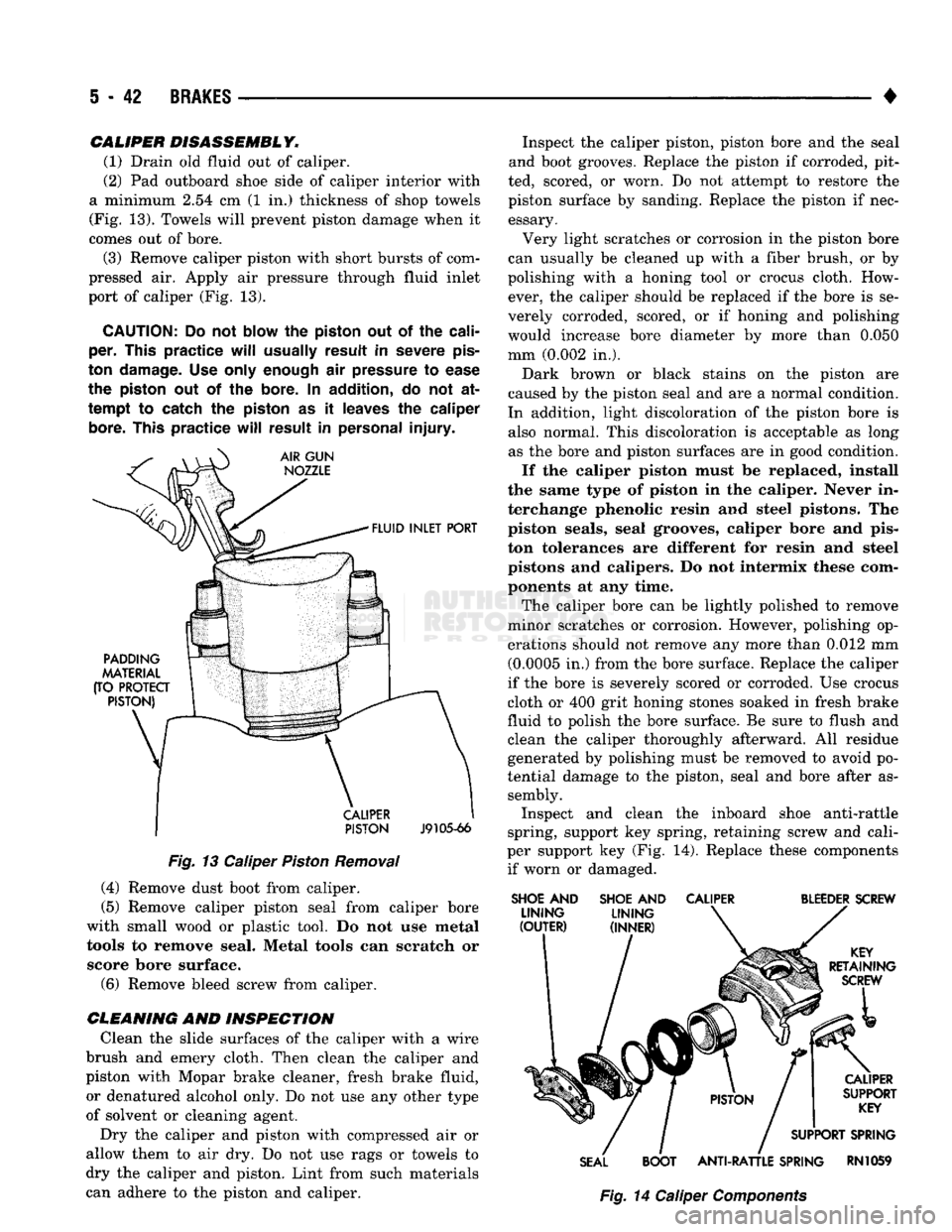
(3) Remove caliper piston with short bursts of com
pressed air. Apply air pressure through fluid inlet
port of caliper (Fig. 13).
CAUTION:
Do not
blow
the
piston
out of the
cali
per.
This
practice
will
usually
result
in
severe
pis
ton
damage.
Use only
enough
air
pressure
to
ease
the
piston
out of the
bore.
In
addition,
do not at
tempt
to catch the
piston
as it
leaves
the
caliper
bore.
This
practice
will
result
in
personal
injury.
PISTON
J9105-66
Fig.
13 Caliper
Piston
Removal (4) Remove dust boot from caliper.
(5) Remove caliper piston seal from caliper bore
with small wood or plastic tool. Do not use metal tools to remove seal. Metal tools can scratch or score bore surface. (6) Remove bleed screw from caliper.
CLEANING
AND INSPECTION Clean the slide surfaces of the caliper with a wire
brush and emery cloth. Then clean the caliper and
piston with Mopar brake cleaner, fresh brake fluid, or denatured alcohol only. Do not use any other type
of solvent or cleaning agent.
Dry the caliper and piston with compressed air or
allow them to air dry. Do not use rags or towels to
dry the caliper and piston. Lint from such materials
can adhere to the piston and caliper. Inspect the caliper piston, piston bore and the seal
and boot grooves. Replace the piston if corroded, pit
ted, scored, or worn. Do not attempt to restore the
piston surface by sanding. Replace the piston if nec essary.
Very light scratches or corrosion in the piston bore
can usually be cleaned up with a fiber brush, or by
polishing with a honing tool or crocus cloth. How ever, the caliper should be replaced if the bore is se
verely corroded, scored, or if honing and polishing
would increase bore diameter by more than 0.050
mm (0.002 in.).
Dark brown or black stains on the piston are
caused by the piston seal and are a normal condition.
In addition, light discoloration of the piston bore is also normal. This discoloration is acceptable as long as the bore and piston surfaces are in good condition.
If the caliper piston must be replaced, install
the same type of piston in the caliper. Never in
terchange phenolic resin and steel pistons. The piston seals, seal grooves, caliper bore and pis
ton tolerances are different for resin and steel
pistons and calipers. Do not intermix these com ponents at any time.
The caliper bore can be lightly polished to remove
minor scratches or corrosion. However, polishing op
erations should not remove any more than 0.012 mm (0.0005 in.) from the bore surface. Replace the caliper
if the bore is severely scored or corroded. Use crocus
cloth or 400 grit honing stones soaked in fresh brake
fluid to polish the bore surface. Be sure to flush and
clean the caliper thoroughly afterward. All residue generated by polishing must be removed to avoid po
tential damage to the piston, seal and bore after as sembly. Inspect and clean the inboard shoe anti-rattle
spring, support key spring, retaining screw and cali
per support key (Fig. 14). Replace these components if worn or damaged.
SHOE
AND
SHOE
AND
CALIPER
BLEEDER
SCREW
SEAL
BOOT
ANTI-RATTLE
SPRING
RN1059
Fig.
14 Caliper
Components
Page 230 of 1502
•
BRAKES
5 - 43
CAMPER
ASSEMBLY
(1) Mount caliper in vise equipped with protective
jaws.
Do not overtighten vise. Excessive pressure could cause bore distortion and piston binding. (2) Lubricate new piston seal and piston bore with
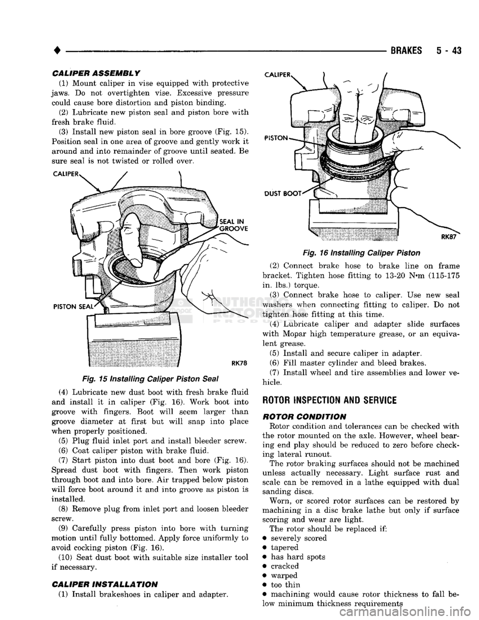
fresh brake fluid. (3) Install new piston seal in bore groove (Fig. 15).
Position seal in one area of groove and gently work it around and into remainder of groove until seated. Be
sure seal is not twisted or rolled over.
Fig.
15 Installing Caliper
Piston
Seal
(4) Lubricate new dust boot with fresh brake fluid
and install it in caliper (Fig. 16). Work boot into
groove with fingers. Boot will seem larger than
groove diameter at first but will snap into place
when properly positioned.
(5) Plug fluid inlet port and install bleeder screw. (6) Coat caliper piston with brake fluid.
(7) Start piston into dust boot and bore (Fig. 16).
Spread dust boot with fingers. Then work piston
through boot and into bore. Air trapped below piston
will force boot around it and into groove as piston is installed.
(8) Remove plug from inlet port and loosen bleeder
screw.
(9) Carefully press piston into bore with turning
motion until fully bottomed. Apply force uniformly to avoid cocking piston (Fig. 16).
(10) Seat dust boot with suitable size installer tool
if necessary.
CALIPER
INSTALLATION
(1) Install brakeshoes in caliper and adapter.
Fig.
16 Installing Caliper
Piston
(2) Connect brake hose to brake line on frame
bracket. Tighten hose fitting to 13-20 N«m (115-175 in. lbs.) torque.
(3) Connect brake hose to caliper. Use new seal
washers when connecting fitting to caliper. Do not
tighten hose fitting at this time.
(4) Lubricate caliper and adapter slide surfaces
with Mopar high temperature grease, or an equiva lent grease.
(5) Install and secure caliper in adapter.
(6) Fill master cylinder and bleed brakes.
(7) Install wheel and tire assemblies and lower ve
hicle.
ROTOR INSPECTION AND
SERVICE
ROTOR
CONDITION
Rotor condition and tolerances can be checked with
the rotor mounted on the axle. However, wheel bear ing end play should be reduced to zero before check
ing lateral runout.
The rotor braking surfaces should not be machined
unless actually necessary. Light surface rust and scale can be removed in a lathe equipped with dual
sanding discs.
Worn, or scored rotor surfaces can be restored by
machining in a disc brake lathe but only if surface scoring and wear are light.
The rotor should be replaced if:
• severely scored
• tapered
• has hard spots
• cracked
• warped
• too thin
• machining would cause rotor thickness to fall be
low minimum thickness requirements
Page 234 of 1502
BRAKES
5 - 47
(8) Disengage and remove adjuster screw assembly
from brakeshoes.
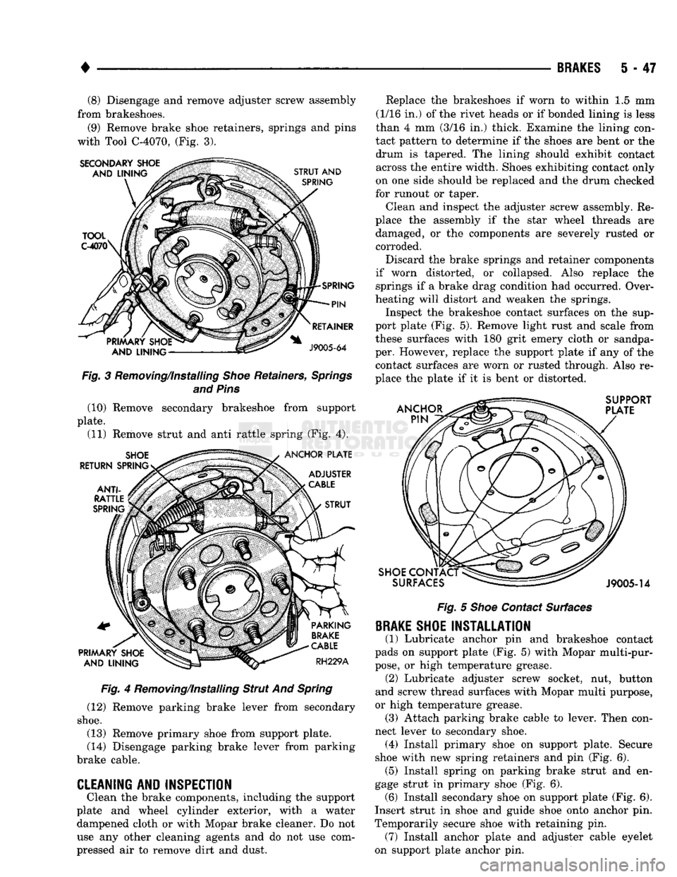
(9) Remove brake shoe retainers, springs and pins
with Tool C-4070, (Fig. 3). Fig. 3 Removing/Installing Shoe Retainers, Springs
and Pins (10) Remove secondary brakeshoe from support
plate. (11) Remove strut and anti rattle spring (Fig. 4).
Fig. 4 Removing/Installing Strut And Spring
(12) Remove parking brake lever from secondary
shoe.
(13) Remove primary shoe from support plate.
(14) Disengage parking brake lever from parking
brake cable.
CLEANING AND INSPECTION
Clean the brake components, including the support
plate and wheel cylinder exterior, with a water dampened cloth or with Mopar brake cleaner. Do not
use any other cleaning agents and do not use com
pressed air to remove dirt and dust. Replace the brakeshoes if worn to within 1.5 mm
(1/16 in.) of the rivet heads or if bonded lining is less
than 4 mm (3/16 in.) thick. Examine the lining con
tact pattern to determine if the shoes are bent or the drum is tapered. The lining should exhibit contact across the entire width. Shoes exhibiting contact only
on one side should be replaced and the drum checked
for runout or taper.
Clean and inspect the adjuster screw assembly. Re
place the assembly if the star wheel threads are damaged, or the components are severely rusted or corroded.
Discard the brake springs and retainer components
if worn distorted, or collapsed. Also replace the springs if a brake drag condition had occurred. Over
heating will distort and weaken the springs. Inspect the brakeshoe contact surfaces on the sup
port plate (Fig. 5). Remove light rust and scale from
these surfaces with 180 grit emery cloth or sandpa
per. However, replace the support plate if any of the contact surfaces are worn or rusted through. Also re
place the plate if it is bent or distorted.
Fig. 5 Shoe Contact Surfaces
BRAKE
SHOE INSTALLATION
(1) Lubricate anchor pin and brakeshoe contact
pads on support plate (Fig. 5) with Mopar multi-pur
pose,
or high temperature grease. (2) Lubricate adjuster screw socket, nut, button
and screw thread surfaces with Mopar multi purpose,
or high temperature grease. (3) Attach parking brake cable to lever. Then con
nect lever to secondary shoe. (4) Install primary shoe on support plate. Secure
shoe with new spring retainers and pin (Fig. 6). (5) Install spring on parking brake strut and en
gage strut in primary shoe (Fig. 6). (6) Install secondary shoe on support plate (Fig. 6).
Insert strut in shoe and guide shoe onto anchor pin.
Temporarily secure shoe with retaining pin. (7) Install anchor plate and adjuster cable eyelet
on support plate anchor pin.
Page 242 of 1502
•
BRAKES
5 - 55 Inspect the cylinder bore. Light discoloration and
dark stains in the bore are normal and will not im
pair cylinder operation. If desired, the bore can be lightly polished but only with crocus cloth. Replace
the cylinder if the bore is scored, pitted or heavily corroded. Honing the bore to restore the surface is not recommended.
Inspect the cylinder pistons. The piston surfaces
should be smooth and free of scratches, scoring and
corrosion. Replace the pistons if worn, scored, or cor
roded. Do attempt to restore the surface by sanding or polishing.
Discard the old piston cups and the spring and ex
pander. These parts are not reusable. The original
dust boots may be reused but only if they are in good condition.
ASSEMBLING
WHEEL CYLINDER
(1) Lubricate wheel cylinder bore, pistons, piston
cups and spring and expander with ^clean brake fluid. (2) Install first piston in cylinder bore. Then in
stall cup in bore and against piston. Be sure lip of
piston cup is facing inward (toward spring and
expander) and flat side is against piston.
(3) Install spring and expanders followed by re
maining piston cup and piston.
(4) Install boots on each end of cylinder and insert
push rods in boots.
(5)
Install cylinder bleed screw.
WHEEL
CYLINDER INSTALLATION
(1) Start brakeline into cylinder.
(2) Position cylinder on support plate and install
cylinder attaching bolts. (3) Tighten brakeline fitting and cylinder attach
ing bolts. (4) Install anchor pin bushing, cam plate, adjuster
cable, parking brake lever, spring washer and anchor
bolt and nut.
(5) Install brakeshoes and brake drum as described
in this section. (6) Install axle shaft.
(7) Install wheel and tire.
(8) Remove supports and lower vehicle.
SUPPORT
PLATE REMOVAL
(1) Raise and support vehicle.
(2) Remove wheel and tire.
(3) Remove axle shaft.
(4) Remove brake drum, brake shoes and wheel
cylinder as described in this section. (5) Remove bolts/nuts attaching support plate to
axle and remove support plate.
SUPPORT PLATE INSTALLATION
(1) Transfer wheel cylinder and parking brake le
ver components to replacement support plate. (2) Position support plate on axle and install at
taching bolts/nuts. (3) Lubricate shoe contact surfaces of support plate
with Mopar multi-purpose, or high temperature bear ing grease. (4) Install brakeshoes. Adjust shoes to drum with
brake gauge. (5) Install brake drum.
(6) Install axle shaft.
(7) Install wheel and tire.
(8) Remove supports and lower vehicle.
Page 270 of 1502
•
CLUTCH
6-17
CLUTCH PEDAL INSTALLATION
(1) Lubricate pedal shaft, pedal shaft bore and all
bushings with Mopar Multi Mileage grease. (2) Insert pedal pin into cylinder push rod. Then
position clutch pedal in support. (3) Slide pedal shaft through clutch pedal bore and
bushings. (4) Install bolt that retains pedal shaft in support.
(5) Secure push rod to pedal pin with wave washer,
flat washer and retaining ring.
FLYWHEEL SERVICE
Inspect the flywheel whenever the clutch disc,
cover and housing are removed for service. Check
condition of the flywheel face, hub, ring gear teeth,
and flywheel bolts. Minor scratches, burrs, or glazing on the flywheel
face can be scuff sanded with 180 grit emery cloth. However, the flywheel should be replaced if the disc
contact surface is severely scored, heat checked,
cracked, or obviously worn. Cleanup of minor flywheel scoring should be per
formed with surface grinding equipment. Remove
only enough material to reduce scoring (approximate
ly 0.001 - 0.003 in.). Heavy stock removal is not rec
ommended. Replace the flywheel if scoring is severe
and deeper than 0.076 mm (0.003 in.). Excessive
stock removal can result in flywheel cracking or
warpage after installation; it can also weaken the flywheel and interfere with proper clutch release. Check flywheel runout if misalignment is sus
pected. Runout should not exceed 0.08 mm (0.003
in.).
Measure runout at the outer edge of the fly
wheel face with a dial indicator. Mount the dial in
dicator on a stud installed in place of one of the
flywheel attaching bolts. Clean the crankshaft flange before mounting the
flywheel. Dirt and grease on the flange surface may cock the flywheel causing excessive runout. Check condition of the flywheel hub and attaching
bolts.
Replace the flywheel if the hub exhibits cracks in the area of the attaching bolt holes. Install new attaching bolts whenever the flywheel
is replaced and use Mopar Lock N' Seal, or Loctite
242 on replacement bolt threads.
Recommended flywheel bolt torques are:
• 75 N»m (55 ft. lbs.) for gas engine flywheels
• 137 N*m (101 ft. lbs.) for diesel flywheels Inspect the teeth on the starter ring gear. If the
teeth are worn or damaged, the flywheel should
be replaced as an assembly. This is the recom mended and preferred method of repair.
In cases where a new flywheel is not readily avail
able,
a replacement ring gear can be installed. How
ever, the following precautions must be observed to
avoid damaging the flywheel and replacement gear.
(a) Mark position of the old gear for alignment
reference on the flywheel. Use a scriber for this
purpose.
(b) Wear protective goggles or approved safety
glasses. Also wear heat resistent gloves when han
dling a heated ring gear. (c) Remove the old gear by cutting most of the
way through it (at one point) with an abrasive cut off wheel. Then complete removal with a cold chisel
or punch. (d) The ring gear is a shrink fit on the flywheel.
This means the gear must be expanded by heating in order to install it. The method of heating and expanding the gear is extremely important. Ev
ery surface of the gear must be heated at the same
time to produce uniform expansion. An oven or
similar enclosed heating device must be used. Tem
perature required for uniform expansion is 325-350° F.
CAUTION:
Never
use an
oxy/acetylene torch
to re
move
the old
gear,
or to
heat
and
expand
a new
gear.
The
high temperature
of the
torch flame
will
cause
localized heating
and
damage
the
flywheel.
In
addition,
using
the
torch
to
heat
a
replacement gear
will
cause uneven heating
and
expansion.
The
torch
flame
will
also
anneal
the
gear
teeth
resulting
in
rapid wear
and
damage
after
installation.
(e) The heated gear must be installed evenly to
avoid misalignment or distortion. A shop press and
suitable press plates should be used to install the
gear if at all possible.
(f) Be sure to wear eye and hand protection.
Heat resistent gloves and safety goggles are needed
for personal safety. Also use metal tongs, vise
grips,
or similar tools to position the gear as necessary for installation.
(g) Allow the flywheel and ring gear to cool
down before installation. Set the assembly on a
workbench and let it cool in normal shop air.
CAUTION:
Do not
use water,
or
compressed
air to
cool
the
flywheel.
The
rapid cooling produced
by
water
or
compressed
air can
distort,
or
crack
the
gear
and
flywheel.
Page 275 of 1502
DIAGNOSIS
PRELIMINARY
CHECKS
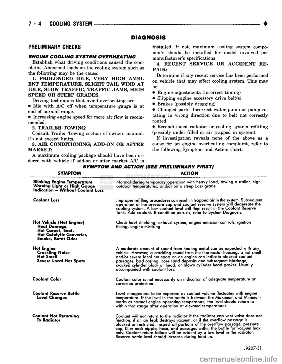
ENGINE COOLING SYSTEM OVERHEATING Establish what driving conditions caused the com
plaint. Abnormal loads on the cooling system such as
the following may be the cause:
1.
PROLONGED IDLE, VERY HIGH AMBI
ENT TEMPERATURE, SLIGHT TAIL WIND AT
IDLE, SLOW TRAFFIC, TRAFFIC JAMS, HIGH SPEED OR STEEP GRADES.
Driving techniques that avoid overheating are:
• Idle with A/C off when temperature gauge is at
end of normal range. * Increasing engine speed for more air flow is recom
mended.
2.
TRAILER TOWING: Consult Trailer Towing section of owners manual.
Do not exceed limits.
3.
AIR CONDITIONING; ADD-ON OR AFTER
MARKET: A maximum cooling package should have been or
dered with vehicle if add-on or after market A/C is
SYMPTOM AND ACTION
SYMPTOM
installed. If not, maximum cooling system compo
nents should be installed for model involved per
manufacturer's specifications.
4.
RECENT SERVICE OR ACCIDENT RE
PAIR:
Determine if any recent service has been performed
on vehicle that may effect cooling system. This may
be:
• Engine adjustments (incorrect timing)
• Slipping engine accessory drive belt(s) • Brakes (possibly dragging)
• Changed parts. Incorrect water pump or pump ro
tating in wrong direction due to belt not correctly
routed
• Reconditioned radiator or cooling system refilling (possibly under filled or air trapped in system).
If investigation reveals none of the above as a
cause for an engine overheating complaint, refer to
the following Symptom and Action chart:
PRELIMINARY FIRST) ACTION
Blinking Engine Temperature
Warning Light or High Gauge indication - Without Coolant Loss
Normal during temporary operation
with
heavy load, towing
a
trailer,
high
outdoor temperatures, and/or on
a
steep
Loss
grade.
Coolant Loss
Hot Vehicle (Not Engine) Heat Damage,
Hot Carpet, Seat,
Hot
Catalytic
Converter,
Smoke, Burnt Odor
Hot Engine Crackling Noise Hot Smell
Severe Local Hot Spots
Coolant Color
Coolant Reserve Bottle Level Changes
Coolant Not Returning To Radiator
Improper refilling procedures
can
result
in
trapped air
in
the
system.
Subsequent
operation
of the
pressure cap and coolant reserve system
will
deaereate
the
cooling
system.
A low
coolant
level
will
then result
in the
Coolant Reserve
Tank. Add coolant.
If
condition persists,
refer
to
System
Diagnosis.
Check
heat shielding, exhaust
system,
engine emission controls, ignition
timing, engine misfiring.
A
moderate amount
of
sound from heating
metal
can
be
expected
with
any
vehicle. However,
a
crackling sound from
trie
thermostat
housing,
a hot
smell and/or severe local
hot
spots on
an
engine can indicate blocked coolant
passages,
bad castina, core sand deposits and subsequent blockage,
cracked cylinder block
or
head,
or
blown cylinder head gasket. Usually
accompanied
with
coolant
loss.
Coolant
color is
not
necessarily
an
indication
of
adequate
temperature
or
corrosion
protection.
Level changes
are to be
expected as coolant volume fluctuates
with
engine
temperature.
If the
level
in the
bottle
is
between
the
Maximum and Minimum
marks
at
normal engine operating temperature,
the
level
should
return
to
within
that
range
after
operation
at
elevated temperatures.
Coolant
will
not
return
to the
radiator
if the
radiator cap vent valve does
not
function,
if
an
air
leak destroys vacuum,
or if the
overflow
passage
is
blocked
or
restricted. Inspect
all
portions
of the
overflow
passage,
pressure
cap,
filler
neck nipple, hose, and
passages
within
the
bottle
for
vacuum leak
only. Coolant
return
failure
will
be
evident
by a low
level
in the
radiator.
Reserve
bottle
level
should increase during heat-up.
J9207-31
Page 276 of 1502
•
COOLING
SYSTEM
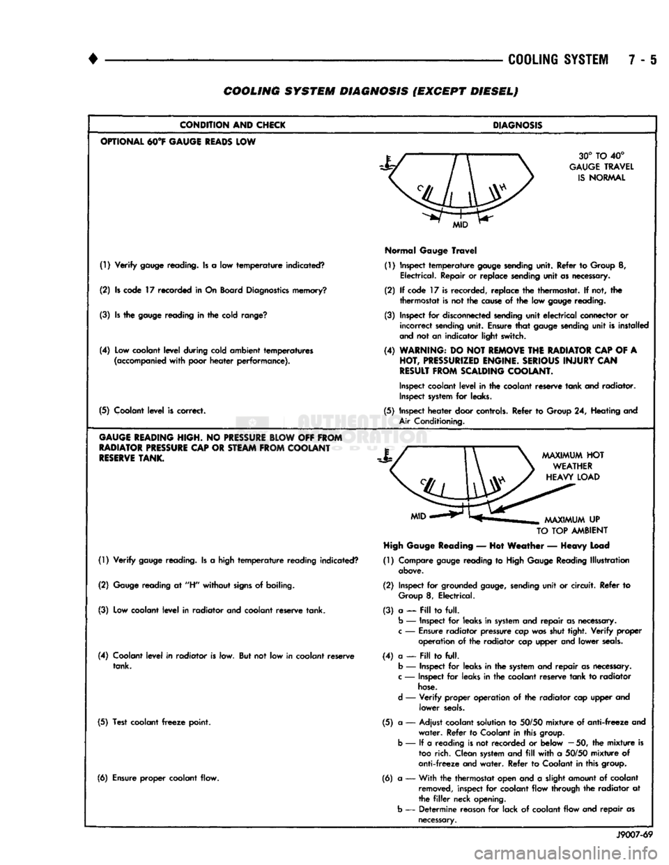
7 - 6 COOLING SYSTEM DIAGNOSIS (EXCEPT DIESEL)
CONDITION
AND
CHICK
OPTIONAL
M°¥
GAUGE
READS
LOW
(!) Verify
gauge
reading. Is a low temperature indicated?
(2) Is code 17 recorded in On Board
Diagnostics
memory?
(3) Is the
gauge
reading in the cold
range?
(4) Low coolant level during cold ambient temperatures
(accompanied
with poor heater performance).
(5) Coolant level is correct.
GAUGE
HEADING
HIGH.
NO
PRESSURE
BLOW
OFF
FROM
RADIATOR
PRESSURE
CAP
OR
STEAM
FROM
COOLANT
RESERVE
TANK.
(1) Verify
gauge
reading. Is a high temperature reading indicated?
(2)
Gauge
reading at
"H"
without
signs
of boiling.
(3) Low coolant level in radiator and coolant reserve tank.
(4) Coolant level in radiator is low. But not low in coolant reserve tank.
(5) Test coolant
freeze
point.
(6) Ensure proper coolant flow.
DIAGNOSIS
30° TO 40°
GAUGE
TRAVEL
IS
NORMAL
Normal
Gauge
Travel
(1) Inspect temperature
gauge
sending
unit. Refer to Group 8, Electrical. Repair or replace sending unit as necessary.
(2) If code 17 is recorded, replace the thermostat. If not, the thermostat is not the
cause
of the low
gauge
reading.
(3) Inspect for
disconnected
sending
unit electrical connector or incorrect
sending
unit. Ensure that
gauge
sending
unit is installed
and
not an indicator light switch.
(4)
WARNING:
DO NOT
REMOVE
THE
RADIATOR
CAP
OF A
HOT,
PRESSURIZED
ENGINE.
SERIOUS
INJURY
CAN
RESULT
FROM
SCALDING
COOLANT.
Inspect
coolant level in the coolant reserve tank and radiator.
Inspect
system
for leaks.
(5) Inspect heater door
controls.
Refer to Group 24, Heating and
Air
Conditioning.
TO
TOP
AMBIENT
High
Gauge
Reading
— Hot Weather — Heavy Load
(1) Compare
gauge
reading to
High
Gauge
Reading Illustration
above.
(2) Inspect for grounded
gauge,
sending
unit or circuit. Refer to
Group
8, Electrical.
(3) a — Pill to full.
b
— Inspect for leaks in
system
and repair as
necessary,
c
—
Ensure
radiator pressure cap was shut tight. Verify
proper
operation of the radiator cap upper and lower
seals.
(4) a —
Fill
to full,
b
— Inspect for leaks in the
system
and repair as
necessary,
c
— Inspect for leaks in the coolant reserve tank to radiator
hose.
d
— Verify proper operation of the radiator cap upper and lower
seals.
(5) a — Adjust coolant solution to
50/50
mixture of anti-freeze and water. Refer to Coolant in this
group,
b
— If a reading is not recorded or below
—
50, the mixture is
too
rich. Clean
system
and
fill
with a
50/50
mixture of
anti-freeze and water. Refer to Coolant in this
group.
(6) a •— With the thermostat open and a slight amount of coolant
removed,
inspect for coolant flow through the radiator at
the
filler
neck opening,
b
— Determine reason for lack of coolant flow and repair as
necessary.
J9007-69
Page 277 of 1502
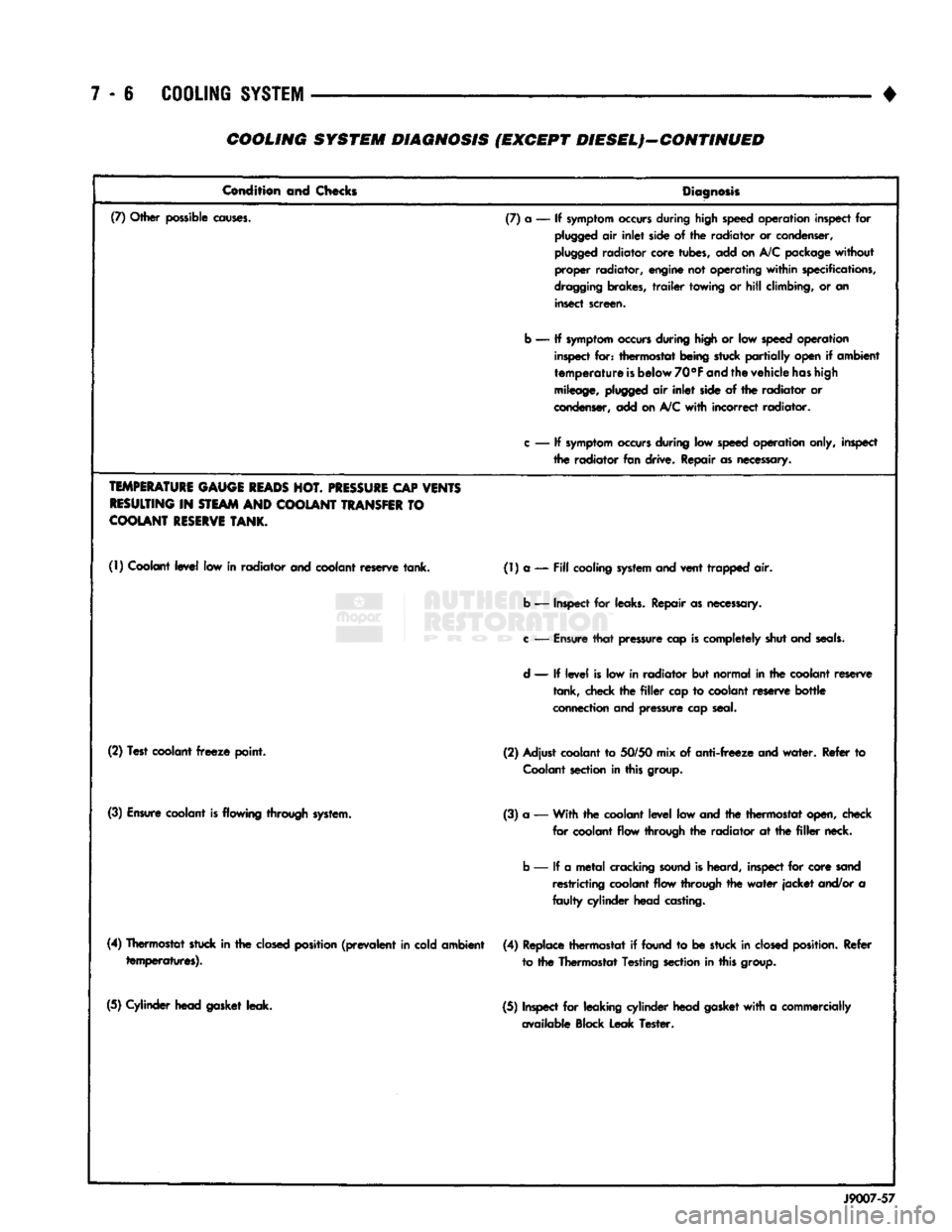
7 - 6
COOLING
SYSTEM
• COOLING SYSTEM DIAGNOSIS (EXCEPT DIESEL)—CONTINUED
Condition and Checks
Diagnosis
(7) Other possible
causes.
(7) a — If
symptom
occurs
during high speed operation inspect for
plugged
air
inlet
side of the radiator or condenser,
plugged
radiator core tubes, add on A/C package
without
proper radiator, engine not operating
within
specifications,
dragging
brakes,
trailer
towing or
hill
climbing, or an insect screen.
b — If
symptom
occurs
during high or low
speed
operation inspect for: thermostat being stuck
partially
open if ambient
temperature
is
below
70°F
and
the vehicle
has
high
mileage,
plugged
air
inlet
side of the radiator or
condenser, add on
A/C
with
incorrect radiator.
c
— If
symptom
occurs
during low
speed
operation only, inspect the radiator fan drive. Repair as necessary.
TEMPERATURE
GAUGE
READS
HOT.
PRESSURE
CAP
VENTS
RESULTING
IN
STEAM
AND
COOLANT
TRANSFER
TO
COOLANT
RESERVE
TANK.
(1) Coolant
level
low in radiator and coolant reserve tank. (1) a —
Fill
cooling
system
and vent trapped air.
b — Inspect for leaks. Repair as necessary.
c
—
Ensure
that
pressure cap
is
completely shut and
seals.
d
— If
level
is low in radiator but normal in the coolant reserve tank, check the
filler
cap to coolant reserve
bottle
connection and pressure cap seal.
(2) Test coolant
freeze
point. (2) Adjust coolant to
50/50
mix of
anti-freeze
and
water.
Refer to
Coolant
section in this group.
(3)
Ensure
coolant
is
flowing through system. (3) a — With the coolant
level
low and the thermostat open, check
for coolant flow through the radiator at the
filler
neck.
b — If a
metal
cracking
sound
is heard, inspect for core sand restricting coolant flow through the
water
jacket
and/or a
faulty
cylinder head casting.
(4) Thermostat stuck in the
closed
position
(prevalent
in cold ambient temperatures). (4) Replace thermostat if found to be stuck in
closed
position.
Refer
to the Thermostat Testing section in this group.
(5) Cylinder head gasket leak. (5) Inspect for leaking cylinder head gasket
with
a commercially
available Block Leak Tester.
J9007-57
Page 278 of 1502
•
COOLING
SYSTEM
7 - 7 COOLING SYSTEM DIAGNOSIS (EXCEPT DIESELJ-GONTINUED
CONDITION
AND
CHECKS
DIAGNOSIS
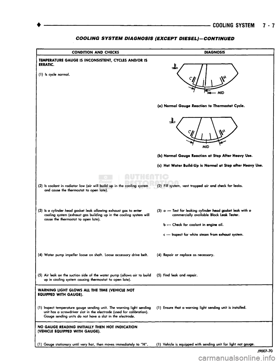
TEMPERATURE
GAUGE
IS
INCONSISTENT,
CYCLES
AND/OR
IS
ERRATIC.
(1) Is cycle normal.
MID
(a)
Normal Gauge Reaction to Thermostat Cycle.
MID
(b) Normal Gauge Reaction at Stop After Heavy Use.
(c) Hot Water Build-Up is Normal at
Stop
after
Heavy Use.
(2)
Is
coolant in radiator low (air
will
build up in the cooling
system
(2)
Fill
system,
vent trapped air and check for leaks,
and
cause
the thermostat to open
late).
(3)
Is
a cylinder head gasket leak allowing exhaust
gas
to
enter
(3) a — Test for leaking cylinder head
gasket
leak
with
a
cooling
system
(exhaust
gas
building up in the cooling
system
will
commercially available Block Leak Tester,
cause
the thermostat to open
late).
b
— Check for coolant in engine oil.
c
— Inspect for
white
steam from exhaust
system.
(4)
Water pump impeller loose on shaft.
Loose
accessory
drive belt. (4) Repair or replace as necessary.
(5)
Air leak
on
the
suction
side of the
water
pump (allows air to build (5) Find leak and repair,
up
in cooling
system
causing
thermostat to open
late).
WARNING
LIGHT
GLOWS
ALL
THE
TIME
(VEHICLE
NOT
EQUIPPED
WITH
GAUGE).
(1) Inspect
temperature
gauge
sending
unit. The warning light
sending
(1)
Ensure
that
a warning light
sending
unit
is
installed, unit
has
a screwdriver slot in the electrode (used for calibration).
Gauge
sending
units do not have a slot in the electrode.
NO
GAUGE
READING
INITIALLY
THEN
HOT
INDICATION
(VEHICLE
EQUIPPED
WITH
GAUGE).
(1)
Gauge
stationary
until
very hot, then
moves
immediately to "H"
(1)
Vehicle
is
equipped
with
sending
unit for light not
gauge.
J9007-70