air condition DODGE TRUCK 1993 Service Workshop Manual
[x] Cancel search | Manufacturer: DODGE, Model Year: 1993, Model line: TRUCK, Model: DODGE TRUCK 1993Pages: 1502, PDF Size: 80.97 MB
Page 315 of 1502
7 - 44
COOLING
SYSTEM
•
Fig.
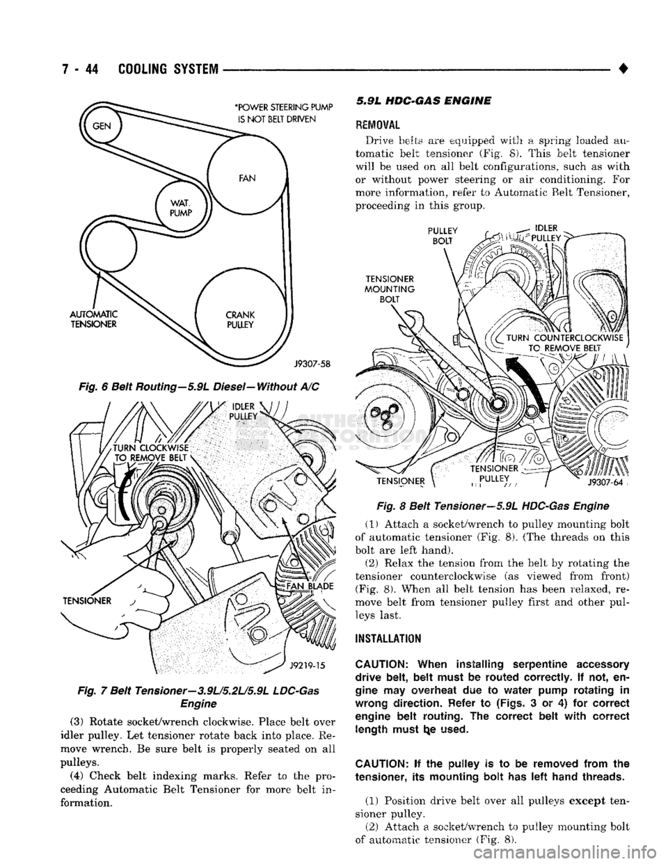
6 Belt Routing-5.9L Diesel-Without A/C
Fig.
7 Belt Tensioner-3.9L/5.2U5.9L
LDC-Gas
Engine
(3)
Rotate socket/wrench clockwise. Place belt over
idler pulley. Let tensioner rotate back into place. Re
move wrench. Be sure belt is properly seated on all
pulleys.
(4)
Check belt indexing marks. Refer to the pro
ceeding Automatic Belt Tensioner for more belt in
formation. 5.9L
HDC-GAS
ENGINE
REMOVAL
Drive belts are equipped with a spring loaded au
tomatic belt tensioner (Fig. 8). This belt tensioner
will be used on all belt configurations, such as with or without power steering or air conditioning. For
more information, refer to Automatic Belt Tensioner,
proceeding in this group.
Fig.
8 Belt Tensioner—5.9L
HDC-Gas Engine
(1) Attach a socket/wrench to pulley mounting bolt
of automatic tensioner (Fig. 8). (The threads on this
bolt are left hand).
(2) Relax the tension from the belt by rotating the
tensioner counterclockwise (as viewed from front) (Fig. 8). When all belt tension has been relaxed, re
move belt from tensioner pulley first and other pul leys last.
INSTALLATION
CAUTION:
When installing serpentine
accessory
drive belt, belt must
be
routed correctly.
If not, en
gine
may
overheat
due to
water pump rotating
in
wrong
direction. Refer
to
(Figs.
3 or 4) for
correct
engine
belt routing.
The
correct belt with correct length must
t^e
used.
CAUTION:
if the
pulley
is to be
removed from
the
tensioner,
its
mounting bolt
has left
hand threads.
(1) Position drive belt over all pulleys except ten
sioner pulley. (2) Attach a socket/wrench to pulley mounting bolt
of automatic tensioner (Fig. 8).
Page 316 of 1502
•
COOLING
SYSTEM
7 - 45 (3) Rotate socket/wrench counterclockwise. Install
belt over tensioner pulley. Let tensioner rotate back into place. Remove wrench. Be sure belt is properly
seated on all pulleys.
5«9L
DIESEL ENGINE
REMOVAL
Drive belts on diesel engines are equipped with a
spring loaded automatic belt tensioner (Fig. 9). Fig
ure 9 displays the tensioner for vehicles without air conditioning.
This belt tensioner will be used on all belt config
urations, such as with or without air conditioning.
For more information, refer to Automatic Belt Ten sioner, proceeding in this group.
Fig.
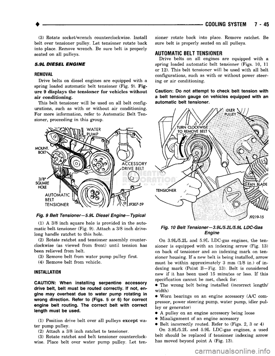
9 Belt Tensioner—5.9L
Diesel
Engine—Typical
(1) A 3/8 inch square hole is provided in the auto
matic belt tensioner (Fig. 9). Attach a 3/8 inch drive-
long handle ratchet to this hole.
(2) Rotate ratchet and tensioner assembly counter
clockwise (as viewed from front) until tension has
been relieved from belt.
(3) Remove belt from water pump pulley first.
(4) Remove belt from vehicle.
INSTALLATION
CAUTION:
When installing serpentine
accessory
drive belt, belt must
be
routed correctly.
If not, en
gine
may
overheat
due to
water pump rotating
in
wrong
direction. Refer
to
(Figs.
5 or 6) for
correct
engine
belt routing.
The
correct belt with correct
length
must
be
used.
(1) Position drive belt over all pulleys except wa
ter pump pulley. (2) Attach a 3/8 inch ratchet to tensioner.
(3) Rotate ratchet and belt tensioner counterclock
wise.
Place belt over water pump pulley. Let ten sioner rotate back into place. Remove ratchet. Be
sure belt is properly seated on all pulleys.
AUTOMATIC
BELT
TENSIONER
Drive belts on all engines are equipped with a
spring loaded automatic belt tensioner (Figs. 10, 11
or 12). This belt tensioner will be used with all belt configurations, such as with or without power steer
ing or air conditioning.
Caution:
Do not
attempt
to
check belt tension with
a
belt tension
gauge
on
vehicles equipped with
an
automatic
belt tensioner. Fig.
10 Belt Tensioner—3.9U5.2U5.9L
LDC-Gas
Engine
On 3.9L/5.2L and 5.9L LDC-gas engines, the ten
sioner is equipped with an indexing arrow (Fig. 13)
on back of tensioner and an indexing mark on ten
sioner housing. If a new belt is being installed, arrow
must be within approximately 3 mm (1/8 in.) of in dexing mark (Point B—Fig. 13). Belt is considered
new if it has been used 15 minutes or less. If this
specification cannot be met, check for:
• The wrong belt being installed (incorrect length/
width)
• Worn bearings on an engine accessory (A/C com
pressor, power steering pump, water pump, idler pul ley or generator)
• A pulley on an engine accessory being loose
• Misalignment of an engine accessory
• Belt incorrectly routed. Refer to (Figs. 2, 3 or 4) On 3.9L/5.2L and 5.9L LDC-gas engines, a used
belt should be replaced if tensioner indexing arrow
has moved beyond point A (Fig. 13).
Page 330 of 1502
•
ELECTRICAL
8A - 9
ENGINE STARTER MOTOR TEST PROCEDURES
GENERAL INFORMATION
The starting system consists of an:
• ignition switch
• starter relay
• park/neutral position switch (automatic transmis sion)
• clutch switch (diesel engine-manual transmission)
• wiring harness
• battery
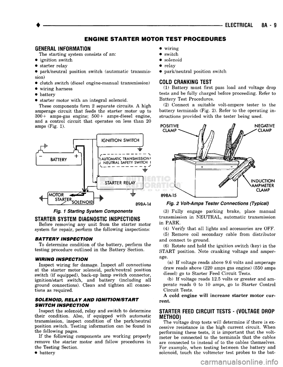
• starter motor with an integral solenoid. These components form 2 separate circuits. A high
amperage circuit that feeds the starter motor up to
300+ amps-gas engine; 500+ amps-diesel engine,
and a control circuit that operates on less than 20
amps (Fig. 1).
a.
BATTERY +
1
IGNITION
SWITCH 1 AUTOMATIC TRANSMISSION
•
J
NEUTRAL SAFETY SWITCH
I 4-
"JL"
MOTOR
m, ...
STA3-TERSOLENO,Dnlh
STARTER RELAY
1"
898A-14
Fig.
1 Starting
System
Components
STARTER SYSTEM DIAGNOSTIC INSPECTIONS
Before removing any unit from the starter motor
system for repair, perform the following inspections:
BATTERY
INSPECTION
To determine condition of the battery, perform the
testing procedure outlined in the Battery Section.
WIRING INSPECTION
Inspect wiring for damage. Inspect all connections
at the starter motor solenoid, park/neutral position
switch (if equipped), back-up lamp switch connector,
ignition/start switch, and battery (including all
ground connections). Clean and tighten all connec
tions as required.
SOLENOID, RELAY
AND
IGNITION/START
SWITCH
INSPECTION
Inspect the solenoid, relay and switch to determine
their condition. Also, if equipped with automatic
transmission, inspect condition of the park/neutral position switch. Testing information can be found in
the following pages.
If the following components are working properly
remove the starter motor and follow procedures in
the Testing Section. • battery wiring
switch
solenoid
relay
park/neutral position switch
COLD CRANKING TEST
(1) Battery must first pass load and voltage drop
tests and be fully charged before proceeding. Refer to Battery Test Procedures. (2) Connect a suitable volt-ampere tester to the
battery terminals (Fig. 2). Refer to the operating in structions provided with the tester being used.
POSITIVE
CLAMP
898A-15
NEGATIVE
CLAMP
INDUCTION
AMPMETER
CLAMP
Fig.
2
Volt-Amps
Tester
Connections
(Typical)
(3) Fully engage parking brake, place manual
transmission in NEUTRAL, automatic transmission
in PARK. (4) Verify that all lights and accessories are OFF. (5) Remove coil secondary cable from distributor
and connect to ground.
(6) Rotate and hold the ignition switch (key) in the
START position. Note cranking voltage and amper
age.
(a) If voltage reads above 9.6 volts and amperage
draw reads above (220 amps gas engine) (550 amps
diesel) go to Starter Feed Circuit Tests. (b) If voltage reads 12.5 volts or greater and am-
perate reads 0 to 10 amps, go to Starter Control Circuit Tests.
A cold engine will increase starter motor cur
rent.
STARTER
FEED
CIRCUIT TESTS
-
(W0LTAGE
DROP
METHOD)
The voltage drop tests will determine if there is ex
cessive resistance in the high current circuit. When
performing these tests, it is important that the volt meter be connected to the terminals that the cables are connected to instead of to the cables themselves.
For example, when testing between the battery and
solenoid, touch the voltmeter test probes to the bat-
Page 334 of 1502
•
ELECTRICAL
8A - 13 GENERATOR TEST PROCEDURES ON
VEHICLE
INDEX
page
Current
Output
Test
......................
14
Diagnostic Procedures
13
General
Information
13
Generator
Output
Wire Resistance Test
.......
13
page
How
to
Use
Malfunction
Indicator
(Check Engine) Lamp
for
Fault
Codes
17
Operational Check
with
Voltmeter
............
13
Using
On-Board Diagnostic System
15
GENERAL
INFORMATION
The generator
is
belt-driven
by the
engine.
All en
gines
use
serpentine drive. The amount
of DC
current produced
by the
gener
ator
is
controlled
by the
Powertrain Control Module (PCM).
All vehicles
are
equipped with
On
Board Diagnos
tics (OBD).
All OBD
sensing systems
are
monitored
by
the PCM. The PCM
will store
in
electronic mem ory
any
detectable failure within
the
monitored cir
cuits.
Refer
to
USING ON-BOARD DIAGNOSTIC SYSTEM
in
this group
for
more information.
OPERATIONAL CHECK
WITH
VOLTMETER
When
the
ignition switch
is
turned
to the RUN po
sition, battery potential will register
on the
voltme
ter. During engine cranking
a
lower voltage will appear
on the
meter. With
the
engine running,
a
voltage reading higher than
the
first reading (igni
tion
in RUN)
should register.
DIAGNOSTIC PROCEDURES
If
the
indicator does
not
operate properly,
or if an
undercharged
or
overcharged battery condition
oc
curs,
the
following procedures
may be
used
to
diag
nose
the
charging system. Remember that
an
undercharged battery
is
often
caused
by:
• accessories being left
on
overnight
•
or by a
defective switch which allows
a
bulb, such
as a
trunk
or
glove
box
light,
to
stay
on
(refer
to
Ignition
Off
Draw).
WISUAL
INSPECTION
• Inspect condition
of
battery cable terminals, bat
tery posts, connections
at
engine block, starter motor solenoid
and
relay. They should
be
clean
and
tight.
Repair
as
required.
• Inspect
all
fuses
in the
fuse block
for
tightness
in
receptacles. They should
be
properly installed
and
tight. Repair
or
replace
as
required.
• Inspect generator mounting bolts
for
tightness.
Re
place
or
torque bolt
as
required (refer
to
Torque Specifications).
• Inspect generator drive belt condition
and
tension.
Tension
or
replace belt
as
required. Refer
to
Belt
Tension Specifications. • Inspect connection
at
generator
B+
output.
It
should
be
clean
and
tight. Repair
as
required.
GENERATOR
OUTPUT
WIRE RESISTANCE TEST
(FIG.
1)
Generator output wire resistance test will show
amount
of
voltage drop across generator output wire
between generator
BAT
terminal
and
battery posi tive post.
PREPARATION
(1) Before starting test make sure vehicle
has a
fully charged battery. Test
and
procedures
on how to
check
for a
fully charged battery
are
shown
in
Bat
tery section
of
this Group.
(2) Turn
OFF
ignition switch.
(3)
Disconnect negative cable from battery.
(4)
Disconnect generator output wire from genera
tor output Battery terminal. (5) Connect
a 0-150
ampere scale
D.C.
ammeter
in
series between generator
BAT
terminal
and
discon
nected generator output wire. Connect Positive lead
to generator
BAT
terminal
and
Negative lead
to
dis connected generator output wire. (6) Connect Positive lead
of a
test voltmeter
(Range
0-18
volts minimum)
to
disconnected genera
tor output wire. Connect negative lead
of
test voltme
ter
to
battery positive cable
at
positive post. (7) Connect
one end of a
Jumper Wire
to
ground
and with other
end
probe green
K20
lead wire
at
back
of
generator
(Fig. 1).
(This will generate
a
fault
code).
CAUTION:
Do not
connect blue
A142
lead
of
wiring
to ground. Refer
to
Group
8W
-
Wiring Diagrams
for
more information.
(8) Connect
an
engine tachometer
and
connect neg
ative cable
to
battery.
(9) Connect
a
variable carbon pile rheostat
be
tween battery terminals.
Be
sure carbon pile
is in
"Open"
or "Off
position before connecting leads.
See
Battery Section, Load Testing
for
instructions.
TEST
(1) Start engine. Immediately after starting,
re
duce engine speed
to
idle.
Page 356 of 1502
•
IGNITION
SYSTEMS
8D - 5
THROTTLE
^
BODY
u
BRACKET
y^SUPPORT
BRACKET
/ |
CHARGE
AIR
ijmmmmk
TEMPERATURE
SENSOR
THROTTLE
BODY
Fig.
9
Sensor
Location—3.9L Engine—Typical
INTAKE MANIFOLD
'b AIR TEMPERATURE
SENSOR
J9314-162
Fig.
10
Sensor
Location—5.2L/5.9L
Engines—Typical
start-up (cranking) and to engine load while the en
gine is running. The PCM uses this input, along with
inputs from other sensors, to adjust air-fuel mixture.
For more information, refer to Group 14, Fuel Sys
tem.
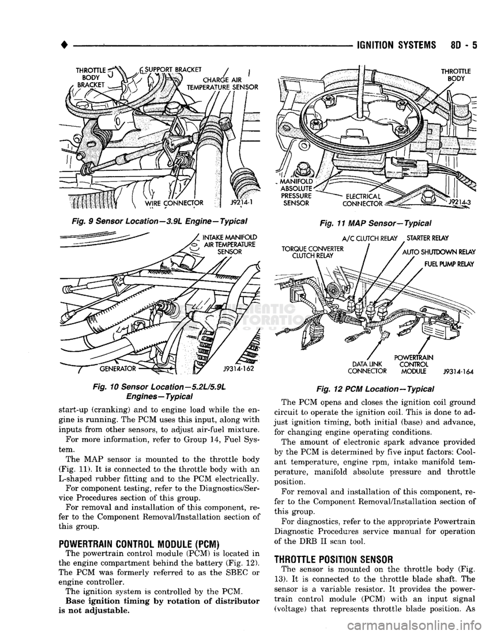
The MAP sensor is mounted to the throttle body
(Fig. 11). It is connected to the throttle body with an
L-shaped rubber fitting and to the PCM electrically. For component testing, refer to the Diagnostics/Ser
vice Procedures section of this group. For removal and installation of this component, re
fer to the Component Removal/Installation section of
this group.
POWERTRAIN CONTROL MODULE
(PCM) The powertrain control module (PCM) is located in
the engine compartment behind the battery (Fig. 12).
The PCM was formerly referred to as the SBEC or engine controller. The ignition system is controlled by the PCM. Base ignition timing by rotation of distributor
is not adjustable.
MANIFOLD
ABSOLUTE
PRESSURE
SENSOR
TORQUE CONVERTER CLUTCH RELAY
ELECTRICAL
Jlp^
CONNECTOR
^gis!—
Fig.
11 MAP Sensor—Typical
A/C
CLUTCH RELAY STARTER RELAY
AUTO
SHUTDOWN RELAY FUEL PUMP RELAY
DATA LINK
CONNECTOR POWERTRAIN
CONTROL
MODULE
J9314-164
Fig.
12 PCM Location—Typical The PCM opens and closes the ignition coil ground
circuit to operate the ignition coil. This is done to ad
just ignition timing, both initial (base) and advance, for changing engine operating conditions.
The amount of electronic spark advance provided
by the PCM is determined by five input factors: Cool ant temperature, engine rpm, intake manifold tem
perature, manifold absolute pressure and throttle
position.
For removal and installation of this component, re
fer to the Component Removal/Installation section of
this group.
For diagnostics, refer to the appropriate Powertrain
Diagnostic Procedures service manual for operation
of the DRB II scan tool.
THROTTLE
POSITION
SENSOR
The sensor is mounted on the throttle body (Fig.
13).
It is connected to the throttle blade shaft. The
sensor is a variable resistor. It provides the power-
train control module (PCM) with an input signal (voltage) that represents throttle blade position. As
Page 361 of 1502
8D
- 10
IGNITION
SYSTEMS
• Arcing at the tower will carbonize the cable boot,
which if it is connected to a new ignition coil, will cause the coil to fail. If the secondary coil cable shows any signs of dam
age,
it should be replaced with a new cable and new
terminal. Carbon tracking on the old cable can cause
arcing and the failure of a new ignition coil.
ENGINE
COOLANT
TEMPERATURE
SENSOR
TEST
To perform a complete test of this sensor and its
circuitry, refer to the DRB II diagnostic scan tool.
Also refer to the appropriate Powertrain Diagnostics
Procedures manual. To test the sensor only, refer to
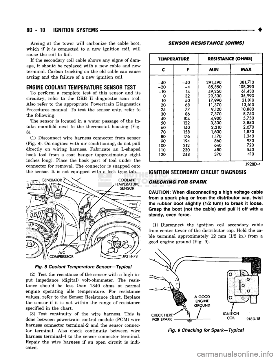
the following: The sensor is located in a water passage of the in
take manifold next to the thermostat housing (Fig.
8).
(1) Disconnect wire harness connector from sensor
(Fig. 8). On engines with air conditioning, do not pull
directly on wiring harness. Fabricate an L-shaped
hook tool from a coat hanger (approximately eight inches long). Place the hook part of tool under the
connector for removal. The connector is snapped onto
the sensor. It is not equipped with a lock type tab.
COOLANT
TEMPERATURE
SENSOR
SENSOR RESISTANCE (OHMSJ
V
J9314-78
Fig. 8 Coolant Temperature Sensor—Typical (2) Test the resistance of the sensor with a high in
put impedance (digital) volt-ohmmeter. The resis tance should be less than 1340 ohms at normal
engine operating idle temperature. For resistance
values, refer to the Sensor Resistance chart. Replace
the sensor if it is not within the range of resistance specified in the chart.
(3) Test continuity of the wire harness. This is
done between powertrain control module (PCM) wire
harness connector terminal-2 and the sensor connec
tor terminal. Also check continuity between wire harness terminal-4 to the sensor connector terminal. Repair the wire harness if an open circuit is indi
cated.
TEMPERATURE
RESISTANCE
(OHMS)
C
F
MIN
MAX
-40 -40 291,490 381,710
-20
-4
85,850
108,390
-10 14
49,250 61,430
0
32 29,330
35,990
10 50 17,990 21,810
20 68 11,370 13,610
25
77 9,120 10,880
30 86
7,370
8,750
40 104
4,900
5,750
50 122
3,330 3,880
60 140 2,310
2,670
70 158
1,630 1,870
80 176
1,170 1,340
90 194
860
970
100 212 640
720
110 230 480 540
120 248 370 410
J928D-4
IGNITION
SECONDARY
CIRCUIT
DIAGNOSIS
CHECKING FOR SPARK
CAUTION:
When
disconnecting a
high
voltage
cable
from
a spark
plug
or
from
the
distributor
cap,
twist
the rubber
boot
slightly
(1/2
turn)
to
break
it
loose.
Grasp
the
boot
(not the cable) and
pull
it off
with
a
steady,
even force.
(1) Disconnect the ignition coil secondary cable
from center tower of the distributor cap. Hold the ca
ble terminal approximately 12 mm (1/2 in.) from a good engine ground (Fig. 9).
CHECK
HERE
FOR
SPARK
IGNITION
COIL
918D-18
Fig. 9 Checking for Spark—Typical
Page 363 of 1502
8D
- 12
IGNITION
SYSTEMS
•
XX
oooooooooo
,0000000000
\2141
3%
lOOOOOOOOOO
OOOOOOOOOO
si
20
fcji^OQOOOOOOJ
«r
~
• • -
•
- - #
•oooooooooo.
CONNECTOR
TERMINAL
SIDE
SHOWN
J908D-42
Fig. 13 PCM 60-Way Connector
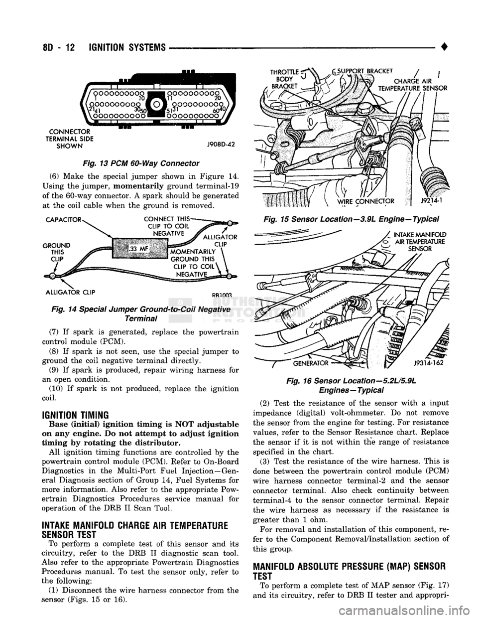
(6) Make the special jumper shown in Figure 14.
Using the jumper, momentarily ground terminal-19
of the 60-way connector. A spark should be generated at the coil cable when the ground is removed.
CAPACITOR
GROUND
THIS
CLIP
CONNECT
THIS-
ALLIGATOR
CLIP
MOMENTARILY
GROUND
THIS
CLIP
TO
COIL^
NEGATIVE
ALLIGATOR
CLIP
PR1003
Fig. 14 Special Jumper Ground-to-Coil Negative Terminal (7) If spark is generated, replace the powertrain
control module (PCM).
(8) If spark is not seen, use the special jumper to
ground the coil negative terminal directly. (9) If spark is produced, repair wiring harness for
an open condition. (10) If spark is not produced, replace the ignition
coil.
IGNITION TIMING
Base (Initial) ignition timing Is NOT adjustable
on any engine. Do not attempt to adjust Ignition
timing by rotating the distributor. All ignition timing functions are controlled by the
powertrain control module (PCM). Refer to On-Board Diagnostics in the Multi-Port Fuel Injection—Gen
eral Diagnosis section of Group 14, Fuel Systems for
more information. Also refer to the appropriate Pow ertrain Diagnostics Procedures service manual for
operation of the DRB II Scan Tool.
INTAKE
MANIFOLD
CHARGE
AIR
TEMPERATURE
SENSOR
TEST
To perform a complete test of this sensor and its
circuitry, refer to the DRB II diagnostic scan tool.
Also refer to the appropriate Powertrain Diagnostics Procedures manual. To test the sensor only, refer to
the following: (1) Disconnect the wire harness connector from the
sensor (Figs. 15 or 16).
THROTTLE
^
BODY
^
BRACKET
SUPPORT BRACKET
/
CHARGE
AIR
TEMPERATURE
SENSOR
Fig. 15 Sensor Location--3.9L Engine—Typical
INTAKE
MANIFOLD
AIR
TEMPERATURE
W
SENSOR
J9314-162
Fig. 16
Sensor
Location—5.2U5.9L
Engines—Typical
(2) Test the resistance of the sensor with a input
impedance (digital) volt-ohmmeter. Do not remove
the sensor from the engine for testing. For resistance
values, refer to the Sensor Resistance chart. Replace
the sensor if it is not within the range of resistance specified in the chart.
(3) Test the resistance of the wire harness. This is
done between the powertrain control module (PCM)
wire harness connector terminal-2 and the sensor connector terminal. Also check continuity between
terminal-4 to the sensor connector terminal. Repair
the wire harness as necessary if the resistance is greater than 1 ohm.
For removal and installation of this component, re
fer to the Component Removal/Installation section of
this group.
MANIFOLD
ABSOLUTE PRESSURE
(MAP)
SENSOR
TEST
To perform a complete test of MAP sensor (Fig. 17)
and its circuitry, refer to DRB II tester and appropri-
Page 364 of 1502
IGNITION
SYSTEMS
8D - 13
SENSOR RESISTANCE (OHMS)
TEMPERATURE
RESISTANCE
(OHMS)
C
F
MIN
MAX
-40 -40 291,490 381,710
-20
-4
85,850 108,390
-10 14 49,250 61,430
0
32 29,330
35,990
10 50 17,990 21,810
20 68 11,370
13,610
25
77 9,120
10,880
30 86
7,370
8,750
40 104
4,900
5,750
50 122
3,330
3,880
60 140 2,310
2,670
70 158
1,630
1,870
80 176
1,170
1,340
90 194 860
970
100 212 640
720
110 230 480
540
120 248 370
410
J928D-4
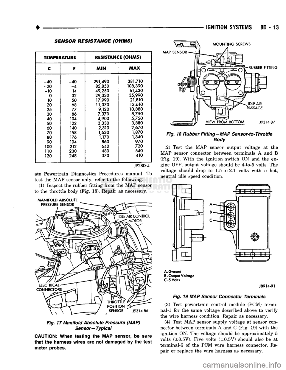
ate Powertrain Diagnostics Procedures manual. To
test the MAP sensor only, refer to the following:
(1) Inspect the rubber fitting from the MAP sensor
to the throttle body (Fig. 18). Repair as necessary.
MANIFOLD
ABSOLUTE
PRESSURE
SENSOR
J9314-86
Fig.
17 Manifold
Absolute
Pressure
(MAP)
Sensor—
Typical
CAUTION:
When
testing
the MAP
sensor,
be
sure
that
the
harness
wires
are not damaged by the
test
meter
probes.
AAAP
SENSOR
MOUNTING
SCREWS
RUBBER
FITTING
J9314-87
Fig.
18
Rubber
Fitting—MAP Sensor-to-Throttle
Body
(2) Test the MAP sensor output voltage at the
MAP sensor connector between terminals A and B (Fig. 19). With the ignition switch ON and the en
gine OFF, output voltage should be 4-to-5 volts. The
voltage should drop to
1.5-to-2.1
volts with a hot, neutral idle speed condition.
A.
Ground
B.
Output
Voltage
C.
5
Volts
J8914-91
Fig.
19 MAP
Sensor
Connector
Terminals
(3) Test powertrain control module (PCM) termi
nal-1 for the same voltage described above to verify
the wire harness condition. Repair as necessary.
(4) Test MAP sensor supply voltage at sensor con
nector between terminals A and C (Fig. 19) with the
ignition ON. The voltage should be approximately 5
volts (±0.5V). Five volts (±0.5V) should also be at
terminal-6 of the PCM wire harness connector. Re pair or replace the wire harness as necessary.
Page 365 of 1502
8D
- 14
IGNITION SYSTEMS
• (5) Test the MAP sensor ground circuit at sensor
connector terminal-A (Fig. 19) and PCM connector
terminal-4. Repair the wire harness if necessary.
(6) Test the MAP sensor ground circuit at the
PCM connector between terminal-4 and terminal-11
with an ohmmeter. If the ohmmeter indicates an
open circuit, inspect for a defective sensor ground
connection. Refer to Group 8W, Wiring for location of
this connection. If the ground connection is good, re
place the PCM. If terminal-4 has a short circuit to 12 volts +, correct this condition before replacing the
PCM.
POWERTRAIN
CONTROL MODULE {PCM)
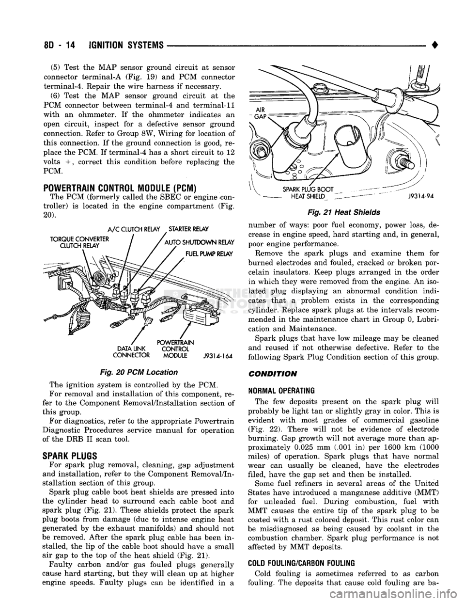
The PCM (formerly called the SBEC or engine -con
troller) is located in the engine compartment (Fig.
20). DATA UNK CONTROL
CONNECTOR MODULE
J9314-164
Fig.
20 PCM Location The ignition system is controlled by the PCM.
For removal and installation of this component, re
fer to the Component Removal/Installation section of
this group.
For diagnostics, refer to the appropriate Powertrain
Diagnostic Procedures service manual for operation
of the DRB II scan tool.
SPARK
PLUGS
For spark plug removal, cleaning, gap adjustment
and installation, refer to the Component Removal/In
stallation section of this group. Spark plug cable boot heat shields are pressed into
the cylinder head to surround each cable boot and
spark plug (Fig. 21). These shields protect the spark
plug boots from damage (due to intense engine heat
generated by the exhaust manifolds) and should not
be removed. After the spark plug cable has been in stalled, the lip of the cable boot should have a small
air gap to the top of the heat shield (Fig. 21). Faulty carbon and/or gas fouled plugs generally
cause hard starting, but they will clean up at higher
engine speeds. Faulty plugs can be identified in a
Fig.
21 Heat
Shields
number of ways: poor fuel economy, power loss, de
crease in engine speed, hard starting and, in general,
poor engine performance.
Remove the spark plugs and examine them for
burned electrodes and fouled, cracked or broken por celain insulators. Keep plugs arranged in the order
in which they were removed from the engine. An iso
lated plug displaying an abnormal condition indi
cates that a problem exists in the corresponding
cylinder. Replace spark plugs at the intervals recom
mended in the maintenance chart in Group 0, Lubri
cation and Maintenance.
Spark plugs that have low mileage may be cleaned
and reused if not otherwise defective. Refer to the
following Spark Plug Condition section of this group.
CONDITION
NORMAL OPERATING
The few deposits present on the spark plug will
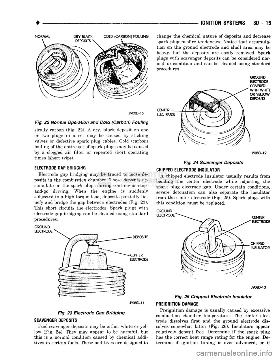
probably be light tan or slightly gray in color. This is evident with most grades of commercial gasoline (Fig. 22). There will not be evidence of electrode
burning. Gap growth will not average more than ap proximately 0.025 mm (.001 in) per 1600 km (1000
miles) of operation. Spark plugs that have normal
wear can usually be cleaned, have the electrodes filed, have the gap set and then be installed.
Some fuel refiners in several areas of the United
States have introduced a manganese additive (MMT)
for unleaded fuel. During combustion, fuel with
MMT causes the entire tip of the spark plug to be coated with a rust colored deposit. This rust color can
be misdiagnosed as being caused by coolant in the combustion chamber. Spark plug performance is not affected by MMT deposits.
COLD
FOULING/CARBON FOULING
Cold fouling is sometimes referred to as carbon
fouling. The deposits that cause cold fouling are ba-
Page 366 of 1502
•
IGNITION
SYSTEMS
8D - 15 J908D-15
Fig.
22 Normal Operation and Cold (Carbon) Fouling
sically carbon (Fig. 22). A dry, black deposit on one
or two plugs in a set may be caused by sticking
valves or defective spark plug cables. Cold (carbon)
fouling of the entire set of spark plugs may be caused
by a clogged air filter or .repeated short operating
times (short trips).
ELECTRODE GAP BRIDGIMG
Electrode gap bridging may be traced to loose de
posits in the combustion chamber. These deposits ac cumulate on the spark plugs during continuous stop-
and-go driving. When the engine is suddenly
subjected to a high torque load, deposits partially liq
uefy and bridge the gap between electrodes (Fig. 28).
This short circuits the electrodes. Spark plugs with electrode gap bridging can be cleaned using standard
procedures.
GROUND
ELECTRODE
J908D-11
Fig. 23 Electrode Gap Bridging
SCAVENGER
DEPOSITS
Fuel scavenger deposits may be either white or yel
low (Fig. 24). They may appear to be harmful, but
this is a normal condition caused by chemical addi
tives in certain fuels. These additives are designed to change the chemical nature of deposits and decrease
spark plug misfire tendencies. Notice that accumula
tion on the ground electrode and shell area may be
heavy, but the deposits are easily removed. Spark
plugs with scavenger deposits can be considered nor mal in condition and can be cleaned using standard
procedures.
GROUND
ELECTRODE
COVERED
J908D-12
Fig.
24
Scavenger
Deposits
CHIPPED ELECTRODE
INSULATOR
A chipped electrode insulator usually results from
bending the center electrode while adjusting the spark plug electrode gap. Under certain conditions, severe detonation can also separate the insulator
from the center electrode (Fig. 25). Spark plugs with
this condition must be replaced.
GROUND
J908D-13
Fig.
25
Chipped
Electrode Insulator
PREIGNITION
DAMAGE
Preignition damage is usually caused by excessive
combustion chamber temperature. The center elec
trode dissolves first and the ground electrode dis solves somewhat latter (Fig. 26). Insulators appear
relatively deposit free. Determine if the spark plug
has the correct heat range rating for the engine. De
termine if ignition timing is over advanced, or if