high beam DODGE TRUCK 1993 Service Repair Manual
[x] Cancel search | Manufacturer: DODGE, Model Year: 1993, Model line: TRUCK, Model: DODGE TRUCK 1993Pages: 1502, PDF Size: 80.97 MB
Page 15 of 1502

10 INTRODUCTION
•
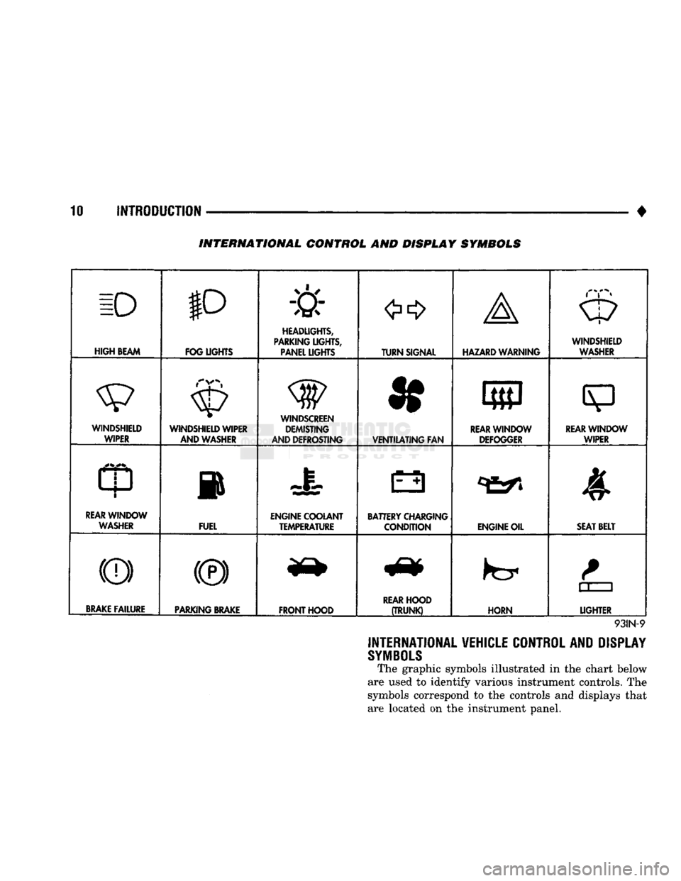
INTERNATIONAL CONTROL AND DISPLAY SYMBOLS
ID
HIGH
BEAM P
FOG UGHTS -&
HEADLIGHTS,
PARKING UGHTS, PANEL UGHTS TURN SIGNAL A
HAZARD WARNING WINDSHIELD
WASHER
WINDSHIELD WIPER WINDSHIELD WIPER
AND WASHER
AND DEFROSTING *
VENTILATING
FAN 8
M f
REAR
WINDOW DEFOGGER
sp
REARWINLX)W WIPER
CD
l
m
REAR
WINDOW WASHER FUEL ENGINE COOLANT
TEMPERATURE BATTERY CHARGING
CONDITION ENGINE OIL
SEAT
BELT
(©) (®) ky
11 J
LIGHTER
BRAKE
FAILURE
PARKING
BRAKE
FRONT HOOD
REAR
HOOD
(TRUNK)
HORN
11 J
LIGHTER
93IN-9
INTERNATIONAL VEHICLE CONTROL AND DISPLAY
SYMBOLS
The graphic symbols illustrated in the chart below
are used to identify various instrument controls. The
symbols correspond to the controls and displays that are located on the instrument panel.
Page 382 of 1502

• • ^ ^ ^ INSTRUMENT PANEL AND GAUGES 8E - 1
CONTENTS
page
CLUSTER AND GAUGE SERVICE PROCEDURES . 12
CLUSTER AND GAUGE TEST PROCEDURES .. i
GENERAL INFORMATION . 1
page
MESSAGE CENTER-DIESEL ENGINE ........ 4
MESSAGE CENTER-GAS ENGINE .......... 3
SWITCH
AND PANEL COMPONENT SERVICE . 16
GENERAL
INFORMATION
INDEX
page
Generator
Indicating
System
2
Distance
Sensor
2
Electronic
Digital
Clock
3
Fuel
Level
Indicating
System
1
page
Malfunction
Indicator
(Check
Engine)
3
Oil
Pressure
Warning
Lamp
................. 2
Speedometer/Odometer
System
2
Temperature
and Oil
Indicating
System
......... 2
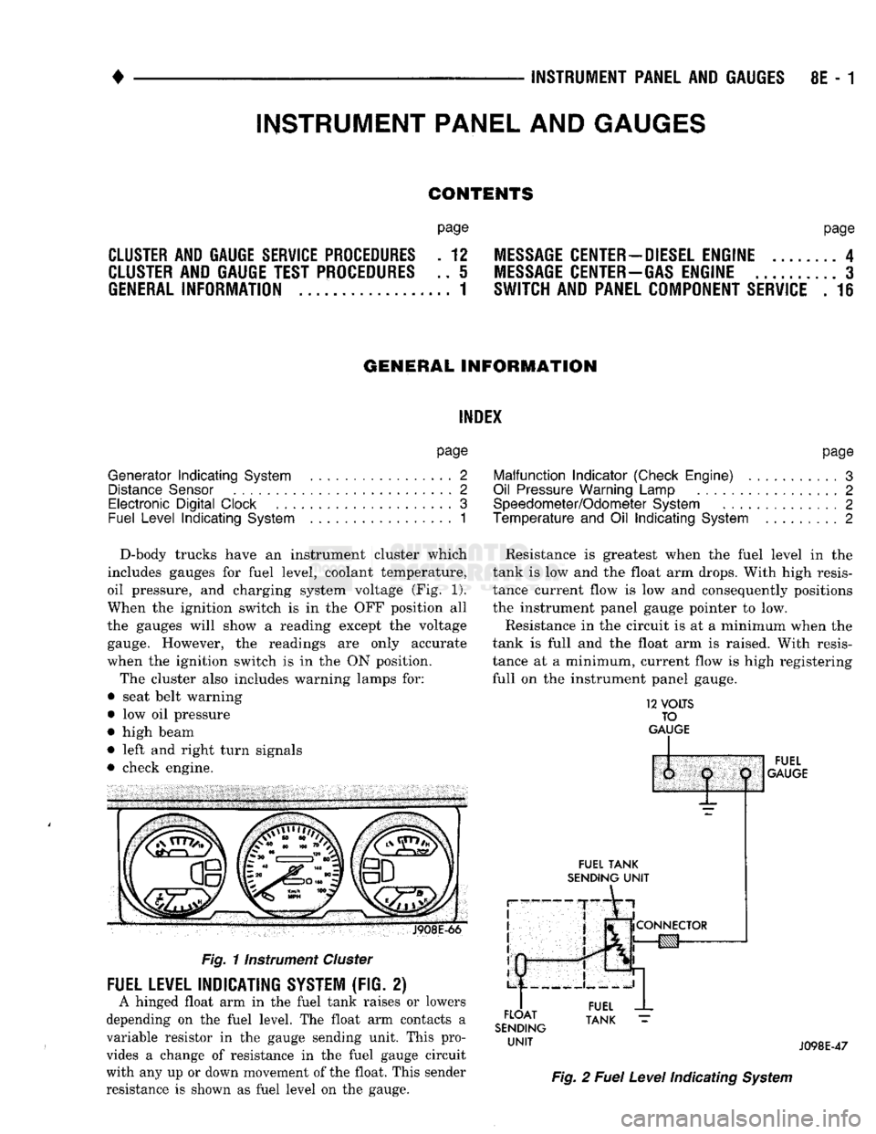
D-body trucks have an instrument cluster which
includes gauges for fuel level, coolant temperature,
oil pressure, and charging system voltage (Fig. 1).
When the ignition switch is in the OFF position all
the gauges will show a reading except the voltage gauge. However, the readings are only accurate
when the ignition switch is in the ON position.
The cluster also includes warning lamps for:
• seat belt warning
• low oil pressure
• high beam
• left and right turn signals
• check engine. J908E-66
Fig.
11nstrument
Cluster
FUEL LEVEL INDICATING SYSTEM (FIG. 2)
A hinged float arm in the fuel tank raises or lowers
depending on the fuel level. The float arm contacts a
variable resistor in the gauge sending unit. This pro
vides a change of resistance in the fuel gauge circuit
with any up or down movement of the float. This sender
resistance is shown as fuel level on the gauge. Resistance is greatest when the fuel level in the
tank is low and the float arm drops. With high resis
tance current flow is low and consequently positions
the instrument panel gauge pointer to low.
Resistance in the circuit is at a minimum when the
tank is full and the float arm is raised. With resis
tance at a minimum, current flow is high registering
full on the instrument panel gauge.
12
VOLTS
TO
GAUGE
IP
FUEL
TANK
SENDING
UNIT
FLOAT
SENDING
UNIT
1:
1
j
^
fCONNECTOR
!g|yj-»—
FUEL
GAUGE
FUEL
TANK
J098E-47
Fig.
2
Fuel
Level
Indicating
System
INSTRUMENT PANEL AND GAUGES
Page 396 of 1502

•
INSTRUMENT PANEL
AND
GAUGES
8E - 15
PRND21 INDICATOR
REMOVAL
(1) Remove bezel. Refer to Cluster Bezel Removal.
(2)
Remove cluster mask and lens. Refer to Cluster
Mask and Lens Removal. (3) Remove cluster assembly. Refer to Instrument
Cluster Removal. (4) Remove screws attaching PRND21 mechanism
to cluster housing.
(5)
Remove PRND21 mechanism.
INSTALLATION (1) Position PRND21 mechanism to cluster hous
ing. (2) Install mounting screws.
(3)
Install cluster assembly. (4) Install mask-lens.
(5)
Install bezel.
LAMP BULBS
CLUSTER ILLUMINATION LAMPS TURN SIGNAL INDICATOR LAMPS
LOW OIL PRESSURE INDICATOR LAMP
HIGH BEAM INDICATOR LAMP CHECK ENGINE LAMP
SEAT BELT WARNING LAMP
REMOVAL (1) Disconnect negative cable from battery.
(2) Remove instrument cluster. See cluster re
moval.
(3)
Twist lamp socket assembly and remove from
printed circuit board. (4) Remove bulb from socket.
INSTALLATION (1) Install bulb into socket.
(2) Install socket assembly into printed circuit
board.
(3)
Position cluster into place in panel. See cluster
installation. (4) Connect battery negative cable.
LAMP BULB REPLACEMENT—MESSAGE CENTER
REMOVAL (1) Disconnect battery negative cable.
(2) Remove instrument cluster bezel assembly. Re
fer to Instrument Cluster removal.
(3)
Twist lamp socket assembly and remove from
printed circuit board. (4) Remove bulb from socket.
INSTALLATION (1) Install bulb into socket assembly. (2) Install lamp socket assembly into printed cir
cuit board.
(3)
Install Instrument Cluster bezel assembly to
instrument panel. Refer to Instrument Cluster instal
lation.
(4) Connect negative cable from battery.
FOUR WHEEL DRIVE INDICATOR LAMP (1) Pull bulb and socket assembly from rear of
housing. (2) Remove bulb from socket.
(3)
Reverse removal procedures to install.
SPECIFICATIONS
Fuel
Gauge Calibration
Mntar Position Resistance
Empty Graduation 90
ohms
± 3
ohms
Empty Stop
Greater
than
96.5 ohms
Full
Graduation 12 ohm
± 3
ohms
Full
Stop
Less
than
8
ohms
1/2
45.3 ohms
± 3
ohms
Temperature
Gauge
Calibration
Pointer
Position Resistance
Cold Graduation 655 ohms
Hot Graduation 64 ohms
Oil Pressure Gauge Calibration
Pointer
Position Resistance
Low Graduation 100 ohms
High Graduation 12 ohms
J908E-58
Page 444 of 1502

•
LAMPS
LAMPS
8L - 1
CONTENTS
page page
BULB
APPLICATION 11 EXTERIOR
LAMPS
SERVICE
PROCEDURES
... 3
EXTERIOR
LAMPS
1 INTERIOR
LAMPS
10
EXTERIOR LAMPS
GENERAL
INFORMATION Each vehicle is equipped with various lamp assem
blies.
A good ground is necessary for proper lighting operation. When changing lamp bulbs check the socket for
corrosion. Clean corrosion with a wire brush. Coat
the inside of the socket lightly with Mopar® Multi- Purpose Grease or equivalent.
DIAGNOSTIC
PROCEDURES
Always begin any diagnosis by testing all of the
fuses and circuit breakers in the system. Refer to Group 8W, Wiring Diagrams. Conventional and halogen headlamps are inter
changeable. It is recommended that they not be in
termixed on a given vehicle.
MULTI-FUNCTION
SWITCH TESTING
PROCEDURES
The multi-function switch contains electrical cir
cuitry for:
• Headlamp Dimmer Switch
• Passing Lights
• Turn Signals
• Hazard Warning • Windshield Wiper
• Pulse Wiper
• Windshield Washer
HEADLAMPS
HIM
ENGINE
IDLING
OR
IGNITION
OFF
TEST CHARGING
SYSTEM
HEADLAMP
DIAGNOSIS
SEALED
BEAM
OR
BULB
BURNS
OUT
FREQUENTLY
][
TEST CHARGING SYSTEM
HEADLAMPS
DIM
ENGINE
RUNNING
ABOVE
IDLE
][
TEST CHARGING SYSTEM
HEADLAMPS
RANDOM
FLASH
[
HEADLAMPS
WILL
NOT
LIGHT
POORLY GROUNDED HEADLAMP CIRCUIT
LOOSE
CONNECTION
IN HEADLAMP CIRCUIT
HIGH RESISTANCE IN HEADLAMP CIRCUIT
LOOSE
CONNECTION
IN HEADLAMP CIRCUIT HIGH RESISTANCE
IN HEADLAMP CIRCUIT
LOOSE
CONNECTION
IN HEADLAMP CIRCUIT OPEN OR CORRODED
CONTACT
IN
HEADLAMP SWITCH
CRACKED
LENS ON HALOGEN SEALED BEAM ONLY
FAULTY
SEALED
BEAMS
OR BULBS OPEN OR CORRODED
CONTACT IN DIMMER SWITCH
FAULTY
SEALED
BEAMS
OR BULBS
FAULTY
SEALED
BEAMS
OR BULBS
RR8LD21
Page 445 of 1502

8L
- 2
LAMPS
• This switch is mounted to the left hand side of the
steering column. Should any function of the switch
fail,
the entire switch must be replaced.
SWITCH
TEST
(1) Disconnect battery negative cable.
(2) Remove tilt lever.
(3) Remove upper and lower column covers to gain
access to the switch connector (Fig. 1).
(4) Remove lower fixed column cover.
(5) Loosen steering column upper bracket nuts. Do
not remove nuts.
(6) Move upper fixed column cover to gain access
to rear of multi-function switch.
(7) Remove switch connector (Figs. 2 and 3). (8) Use an ohmmeter to test for continuity. Check
between the terminals of the switch as shown in the continuity chart (Fig. 4).
(9) Refer to Service Procedures for assembly.
UPPER SHROUD GROUND
CLIP UPPER
FIXED SHROUD
SUPPORT BRACKET
LOWER
SHROUD LOWER
FIXED
SHROUD
J9119-22
Fig.
1 Steering
Column
Covers
STEERING
COLUMN
ASSY.
J918J-1
TURN
SIGNAL
MULT
I
SWITCH
AND
*® FUNCTION
LEVER
SWITCH
CONNECTOR
Fig.
2 Multi-function
Switch
Connector
KEY-IN
SWITCH
&
HALO
LIGHT
MULTIFUNCTION
SWITCH
IGNITION
SWITCH
TURN
SIGNAL
SWITCH
&
LEVER
SPEED
CONTROL
J918J-2
Fig.
3 Steering
Column
Connectors
24 23 22 21 20 19 18
EZJ
C=3 C=3 E=3
CZZJ
E=3 E=3
17 16 15 14 13 12 11 10
a a a 8=3 ( ( ) ) 1=3 1=3 1=3 9 8 7 6 \5_y4 3 2 1
VIEW
FROM
TERMINAL
SIDE
SWITCH POSITION CONTINUITY BETWEEN
LOW
BEAM
HIGH
BEAM
OPTICAL
HORN
18 AND 19
19 AND 20
20
AND
21
908J-5
Fig.
4
Beam
Select
Switch
Continuity Chart
Page 446 of 1502

•
LAMPS
8L - 3
EXTERIOR
LAMPS
SERWICE PROCEDURES
INDEX
page
Cargo
Lamp
7
Clearance Lamps
for
Dual Wheel Model
........
5
Daytime Running
Light
Module (Canada Only)
... 8
Front
Park
and
Turn Signal Lamp Bulb
4
Headlamp
Adjustment
Using
Alignment
Screen
... 3
Headlamp
Alignment
3
Headlamp
Alignment
Preparation
3
page
Headlamp Switch
4
License
Lamp
............................
7
Sealed
Beam Replacement
4
Side
Marker Lamp
and
Bulb
. 5
Tail,
Stop, Turn Signal, Rear Side Marker
and
Back-Up
Lamps
5
Underhood Lamp
8
HEADLAMP
ALIGNMENT
Headlamps
can be
aligned using
the
screen method
provided
in
this section. Alignment Tool C4466-A
or
equivalent
can
also
be
used. Refer
to
instructions
provided with
the
tool
for
proper procedures.
The
preferred headlamp alignment setting
is 0 for
the left/right adjustment
and
1" down
for the up/
down adjustment.
HEADLAMP
ALIGNMENT PREPARATION
(1) Verify headlamp dimmer switch
and
high beam
indicator operation. (2) Correct defective components that could hinder
proper headlamp alignment. (3) Verify proper tire inflation. (4) Clean headlamp lenses.
(5) Verify that luggage area
is not
heavily loaded.
(6) Fuel tank should
be
FULL.
Add 2.94 kg (6.5
lbs.)
of
weight over
the
fuel tank
for
each estimated
gallon
of
missing fuel.
HEADLAMP
ADJUSTMENT USING ALIGNMENT
SCREEN
ALIGNMENT SCREEN PREPARATION (1) Position vehicle
on a
level surface perpendicu
lar
to a
flat wall
7.62
meters
(25 ft)
away from front
of headlamp lens.
(2)
If
necessary, tape
a
line
on the
floor
7.62
meters
(25 ft)
away from
and
parallel
to the
wall.
CENTER
OF
VEHICLE
TO
CENTER
OF
HEADLAMP
LENS
VEHICLE
CENTERLINE" LOW BEAM
HOT
SPOT AREA FLOOR
TO
CENTER
OF
HEADLAMP
LENS
PREFERRED
HOT SPOT
LOCATION
7.62
METERS
(25
FEET)
FRONT
OF
HEADLAMP
938L-25X
Fig.
1 Headlamp
Alignment
Screen
—Typical
Page 447 of 1502

8L
- 4
LAMPS
• (3) Up 1.27 meters (5 feet) from the floor, tape a
line on the wall at the centerline of the vehicle.
Sight along the centerline of the vehicle (from rear of
vehicle forward) to verify accuracy of the line place
ment.
(4) Rock vehicle side-to-side three times to allow
suspension to stabilize. (5) Jounce front suspension three times by pushing
downward on front bumper and releasing. (6) Measure the distance from the center of head
lamp lens to the floor. Transfer measurement to the alignment screen (with tape). Use this line for up/
down adjustment reference.
(7) Measure distance from the centerline of the ve
hicle to the center of each headlamp being aligned. Transfer measurements to screen (with tape) to each side of vehicle centerline. Use these lines for left/
right adjustment reference.
HEADLAMP
ADJUSTMENT
A properly aimed low beam headlamp will project
top edge of high intensity pattern on screen from 50 mm (2 in.) above to 50 mm (2 in.) below headlamp
centerline. The side-to-side outboard edge of high in
tensity pattern should be from 50 mm (2 in.) left to 50 mm (2 in.) right of headlamp centerline (Fig. 1).
The preferred headlamp alignment is 0 for the
up/down adjustment and 1" down for the left/
right adjustment. The high beam pattern should be correct when the iow beams are aligned properly (Fig. 2).
To adjust headlamp aim, rotate alignment screws
to achieve the specified high intensity pattern.
1.
HORIZONTAL
ADJ. SCREW
- RH
2.
VERTICAL
ADJ. SCREW
3.
HORIZONTAL
ADJ. SCREW
- LH
J908L-24
Fig.
2
Sealed
Beam
Headlamp
Alignment
SEALED
BEAM REPLACEMENT
(1) Remove the headlamp bezel (Fig. 3).
(2) Remove four screws from retaining ring (Fig.
4).
(3) Separate sealed beam from seat and disconnect
from the socket. To install, reverse the removal procedures.
HEADLAMP
BEZEL
: ') J918L-29
Fig.
3 Headlamp
Bezel
RETAINING
RING
SCREWS
J918L-28
Fig.
4
Sealed
Beam
Replacement
HEADLAMP SWITCH
To remove or replace the headlamp switch see in
structions in Group 8E - Instrument Panel and
Gauges.
FRONT
PARK AND
TURN
SIGNAL LAMP BULB
(1) Remove 2 screws securing the Park/Turn signal
lamp (Fig. 5) (2) Twist out lamp socket from back of lamp hous
ing. (3) Replace bulb.
To install, reverse removal procedures.
Page 454 of 1502

•
LAMPS
8L - 11
BULB
APPLICATION
GENERAL
INFORMATION
The following Bulb Application Table lists
the
lamp title
on the
left side
of the
column
and
part
number
on the
right.
CAUTION:
Do not use
bulbs
that
have
a
higher
can
dle power than
the
bulb
listed
in the
Bulb
Applica
tion Table.
Damage
to
lamp
can
result.
EXTERIOR LAMPS
Auxiliary Turn Signal (Snow Plow) 2057
Auxiliary Headlamps (Snow Plow) .6054
Back-up....................... .......1156 Cargo Lamp..
922
Clearance Lamps
194
Front Side Marker
168
Headlamp/Sealed Beam .6052
License Plate
168
Park/Turn Signal 2057
TaiyStop/Turn Signal ...2057
INTERIOR LAMPS
DIMMER CONTROLLED LAMPS Service procedures
for
most
of the
lamps
in the in
strument panel
are
located
in
Group
8E,
Instrument
Panel
and
Gauges. Some components have lamps
that
can
only
be
serviced
by an
Authorized Service Center (ASC). These components must
be
removed
from
the
vehicle
for
service. Contact local dealer
for
location
of
nearest
ASC.
A/C Heater Control
158
Ash Receiver
..158
Gear Shift Selector...........................................PC194
Heater Control
158
Instrument Cluster.. PC 194
Radio
ASC
Snow Plow Control
.158
INDICATOR LAMPS Service procedures
for
most
of the
lamps
in the in
strument panel,
and
switches
are
located
in
Group
8E,
Instrument Panel
and
Gauges. Anti-lock Brake PC194
Brake Warning PC194 Check Engine PC194
Engine
Oil
Pressure
158
Fasten Seat Belts.. PC 194 Four Wheel Drive ....158
Hazard Flasher
194
High Beam PC194
Low Fuel....... JPC194
Maintenance Required PC 194
Transmission Temperature ..PC 194 Turn Signal PC194
NON-DIMMING LAMPS Service procedures
for
most
of the
lamps
in the
fol
lowing list
can be
found
in
Group
23,
Body.
Dome
1004
Engine Compartment ...105 Glove Compartment....
1891
Ignition Lock
ASC
Reading Lamp
912
Page 513 of 1502

8W
- 38
WIRING
DIAGRAMS
• Wiring Diagram Name Sheet Number
EMCC
Relay
11
EMCC
Solenoid
11
Ground
11
EMCC
Relay
with Gas
Engine
11,16
EMCC
Solenoid
with Gas
Engine
11,12
Engine
Oil
Pressure Sending
Unit
.27,28
Engine
Starter
Motor
7,9
Engine
Starter
Relay
.7,9
Engine
Starter
System 1,7,8,9 Back-Up Lamp
Switch
.7,9
Bypass
Jumper
(Clutch
Pedal
Position)
8
Clutch
Pedal
Position
Switch
8
Fuse
. 7,9
Motor
7,9
Park/Neutral
Position
Switch
. .7,9
Relay
7,9
Engine Temp Sending
Unit
.
.27,28
Flasher-Hazard Warning
.56
Flasher-Turn Signal
56
Four Wheel
Drive
Indicator
Lamp
13
Front
End
Lighting
. .
.43,44
Front
End
Lighting
(Canada) 45,46
Fuel
Gauge
81,82
Fuel
Tank Gauge
Level
Sending
Unit
Diesel Engine
77
Fuel
Tank Gauge
Level
Sending
Unit
with Gas
Engine
78
Fuel
Heater
Diesel Engine
24
Fuel
Solenoid Diesel Engine
.24
Fuse
Application
Chart
1,2
Fuse
Block Module
and
Relay Bank
82
Fuses
Fuse
1 2,36
Fuse
2
.........
2,10,12,13,14,58,77,78
Fuse
3
2,7,9,10,39
Fuse
4
1,30,47
Fuse
5
1,77,78
Fuse
6
......
.1,73
Fuse
7
1,10,52
Fuse
8
.2,10,61,63
Fuse
9
.2,10,31,33,56
Fuse
10
.2,10,54,55
Fuse
11
2,10,66,67,69
Fuse
12
2,10,71
Fuse
13 1,56
Fuse
14
1,47,52,61,63
Fuse
15
1,49,51,52,61,63,75
Fusible Links 1,2,3,4,5,6,21
Gas
Engine
Wiring
Connector
89
Gauge-Fuel .77,78
Generator
.4,6
Glove
Box
Lamp
Switch
52
Hazard Warning System
. .56
Headlamp Dimmer
Switch
47
Headlamp
Switch
1,47
Headlamp
Switch
Controlled
Interior
Lamps
Headlamps 43,44,
Heated
Rear Window
(Sport
Utility)
Heater
Motor
Resistor
Heater
System Wiring Diagram Name Sheet Number
Horn System
30
Identification
Lamps-Dual Rear Wheels
41,42
Identification
Lamps-Roof Mounted
. 40
Ignition
Coil
.16
Ignition
Switch
.2,10
Ignition
Switch
System
10
Ignition
System (Gas Engine)
.........
.15,16,17,18,19,20
Automatic
Shut Down Relay
.16
Camshaft
Position
Sensor
20
Crankshaft
Position
Sensor
.18
Data
Link
Connector
* . . .17
Engine Coolant Temp
Sensor
20
EVAP
Purge Solenoid
16
Exhaust Gas
Recirculation
Solenoid
16
Fuel
Pump Relay
.16
Heated
Oxygen
Sensor
. . . 17
Idle
Air
Control
Motor
.19
Ignition
Coil
.15
Injectors
.15
Intake
Air
Temp
Sensor
. .20
Map
Sensor
. .20
Powertrain
Control
Module .15,16,17,18,19,20
Throttle
Position
(Sensor)
.18
Vehicle
Speed
Sensor
.20
Ignition
Time
Delay Relay
49
Injectors
.15 Intermittent
Wiper
System .53,54
Control
Unit
.54 Intermittent
Windshield
Wiper
Motor
54
Windshield
Washer Pump
Motor
53
Wiper
Switch
53
Key-In
Switch
49
Key-In Warning Buzzer 77,78
Lamps
Air-Conditioning
and
Heater
Switch
Lamp
48
Ash
Receiver .48,52 Back-Up Lamps
......
79,80,81
Cargo Lamp
.
.49,50 Clearance Lamps-Dual Rear Wheels .41,42
Clearance Lamps Roof Mounted
.40
Cluster
Illumination
Lamps
.
.57,58,59
Dome Lamp
50,51
Four Wheel
Drive
Indicator
.13
Glove
Box
Lamp
52
Headlamp-Left
43,45 Headlamp-Right 44,46
Headlamp
Switch
Controlled
Interior
Lamps
. 48
Heater
Switch
Lamp
.48
High Beam
Indicator
Lamp
.59
Identification
Lamp
.
.40,41
Ignition
Switch
Lamp
.49
Instrument
Panel
Illumination
Lamps
.
.57,58,59
License Lamp
. . . 80
.
.48 Low
Engine
Oil
Pressure Lamp
59
45,46
Map
Lamp
49
.
.39
Parking
Lamp-Left
Front
43,45
66,67 Parking Lamp-Right
Front
44,46 .
.66
Rear
End
Lighting
System .79,80,81
Page 575 of 1502

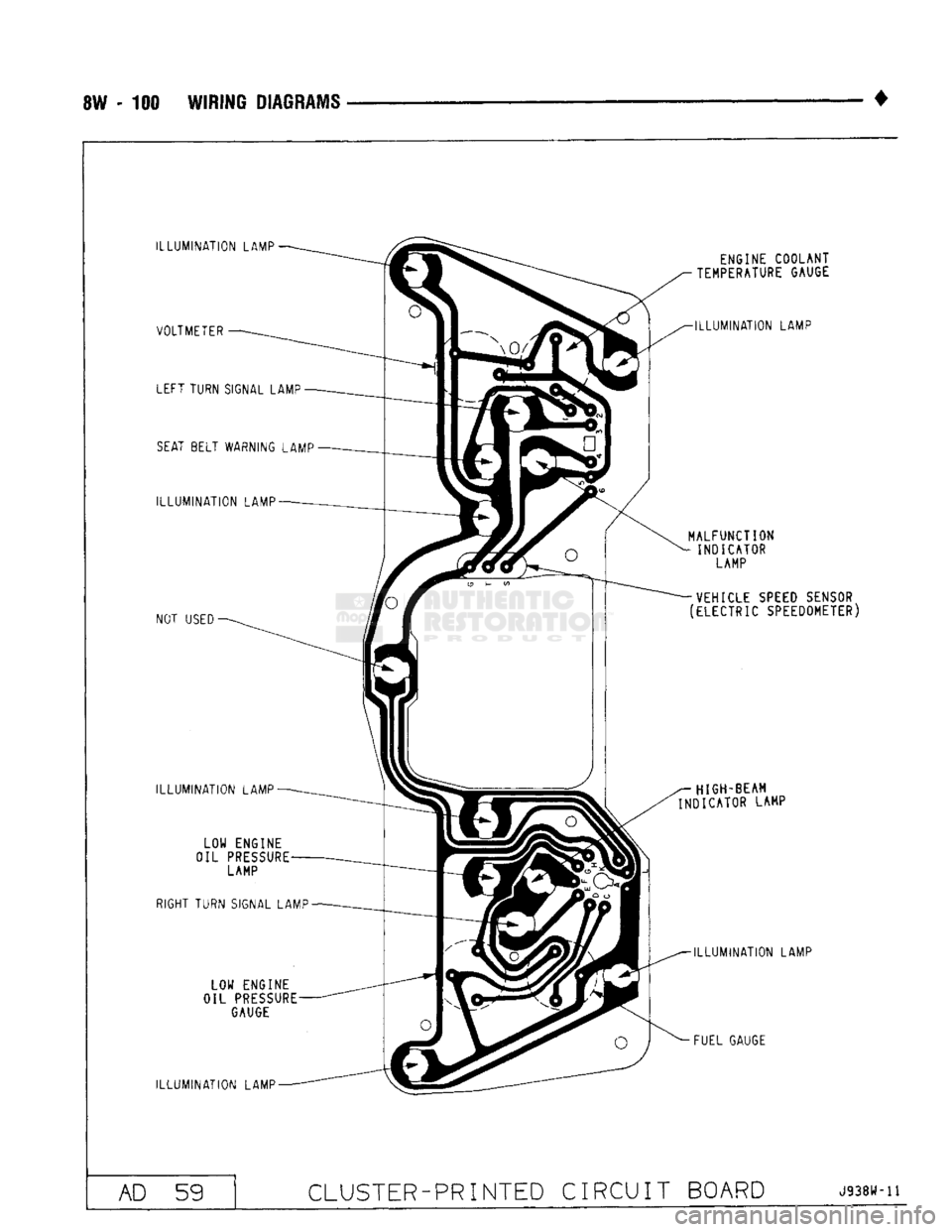
8W - 100 WIRING DIAGRAMS
ILLUMINATION
LAMP VOLTMETER LEFT TURN SIGNAL LAMP
SEAT
BELT WARNING LAMP
ILLUMINATION
LAMP
NOT
USED
ILLUMINATION
LAMP LOW ENGINE
OIL
PRESSURE
LAMP
RIGHT TURN SIGNAL LAMP
LOW ENGINE
OIL
PRESSURE
GAUGE
ILLUMINATION
LAMP ENGINE COOLANT
TEMPERATURE GAUGE
ILLUMINATION
LAMP
MALFUNCTION
INDICATOR LAMP
VEHICLE SPEED SENSOR
(ELECTRIC SPEEDOMETER)
HIGH-BEAM
INDICATOR LAMP
ILLUMINATION
LAMP
FUEL GAUGE AD 59
CLUSTER-PRINTED
CIRCUIT BOARD
J938W-11