battery replacement DODGE TRUCK 1993 Service Owner's Manual
[x] Cancel search | Manufacturer: DODGE, Model Year: 1993, Model line: TRUCK, Model: DODGE TRUCK 1993Pages: 1502, PDF Size: 80.97 MB
Page 427 of 1502
8H
- 12
VEHICLE SPEED CONTROL SYSTEM
•
SERVO
THROTTLE CABLE ASSEMBLY—DIESEL
ENGINE
REMOVAL (1) Remove hairpin clip and washer retaining ca
bles on bellcrank. Remove servo throttle cable from bellcrank.
(2) Remove servo throttle cable from cable support
bracket.
(3) Remove 2 nuts from servo mounting bracket.
(4) Pull servo away from mounting bracket.
(5) Remove and discard push nuts on servo studs. (6) Pull speed control cable away from servo to ex
pose cable retaining clip. (7) Remove clip attaching cable to servo.
(8) Disconnect cable at servo and remove cable as
sembly.
INSTALLATION (1) Locate cable through servo mounting bracket.
(2) Connect cable sleeve to servo stud, align holes,
and install hairpin clip.
(3) Insert servo studs through holes in cable.
(4) Install new push nuts on servo studs.
(5) Insert servo studs through holes in bracket. In
stall nut washers and torque to 6 N*m (50 in. lbs.).
(6) Route cable from servo, to cable support
bracket, (7) Install cable end on bellcrank rod.
(8) Adjust cable as described under speed control
cable adjustment. (9) Install washer and hairpin clip on end of bell
crank rod.
SPEED
CONTROL
SWITCH
REPLACEMENT
(1) Disconnect negative cable from battery.
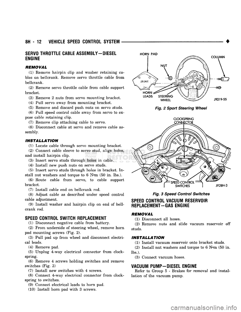
(2) From underside of steering wheel, remove horn
pad mounting screws (Fig. 2).
(3) Pull pad up from wheel and disconnect electri
cal leads.
(4) Remove pad.
(5) Unplug 4-way electrical connector from clock-
spring. (6) Remove 4 screws holding switches and remove
switches (Fig. 3) (7) Install new switches with 4 screws.
(8) Connect 4-way electrical connector from clock-
spring to switches. (9) Connect electrical leads to horn pad.
(10) Install horn pad with 3 screws.
HORN
PAD
Fig. 2 Sport Steering Wheel
CLOCKSPRING
Fig. 3 Speed Control Switches
SPEED
CONTROL VACUUM RESERVOIR
REPLACEMENT-GAS
ENGINE
REMOVAL (1) Disconnect all hoses.
(2) Remove nuts and slide vacuum reservoir off
studs.
INSTALLATION (1) Install vacuum reservoir onto bracket studs.
(2) Install nut washers and torque to 6 Nrn (50 in.
lbs.).
(3) Connect vacuum hoses.
VACUUM PUMP-DIESEL ENGINE
Refer to Group 5 - Brakes for removal and instal
lation of the vacuum pump.
Page 439 of 1502

8K
- 8
WINDSHIELD WIPER
AND
WASHER
SYSTEMS
•
CAUTION:
The use of a screwdriver or other prying
tool to remove an arm may distort it.
This
distortion
could
allow the arm to
come
off the pivot
shaft,
re
gardless
of how carefully it is installed.
INSTALLATION
With wiper motor in park position, mount arms on
pivot shafts. Choose a serration engagement which locates blades so that distance between the intersec
tion of arm and the blade and the weatherstrip is as shown in Fig. 5.
ADJUST WIPER ARM
SO
TIP OF
BLADE
IS
ABOVE
THE WEATHERSTRIP
IN
PARK
POSITION
AS
SHOWN
J908K-34
Fig.
5 Adjusting Wiper
Arms
WIPER MOTOR REPLACEMENT
REMOVAL
(1) Disconnect negative cable from battery.
(2) Disconnect wires from wiper motor.
(3) Remove motor mounting screws.
(4) Lower motor down far enough to gain access to
crank arm to drive link retainer bushing. (5) Remove crank arm from drive link by prying
retainer bushing from crank arm pin with a suitable size screwdriver.
(6) Remove motor.
(7) Remove nut attaching crank arm to motor
drive shaft.
(8) Remove crank arm.
INSTALLATION
(1) Position crank arm on motor drive shaft, mak
ing sure slot is indexed properly. Install mounting
nut and tighten to 11 N»m (95 in. lbs.) torque.
(2) Install crank arm pin in drive link retainer
bushing by snapping together with channel lock pli
ers.
(3) Position motor into place, install mounting
screws, and tighten to 6 N»m (55 in. lbs.) torque. (4) Connect wires to wiper motor. (5) Connect battery cable.
LINKAGE
REPLACEMENT
(Fig. 8)
CRANK
ARM
REMOVAL
(1) Remove wiper motor as previously described. (2) Remove nut attaching crank arm to motor
drive shaft.
(3) Remove crank arm.
INSTALLATION
(1) Position crank arm on motor drive shaft, mak
ing sure slot is indexed properly. Install mounting
nut and tighten to 11 N*m (95 in. lbs.) torque.
(2) Install wiper motor.
DRIVE LINK ASSEMBLY
LEFT
PIVOT
ASSEMBLY
REMOVAL
(1) Remove wiper arms.
(2) Remove screws attaching louvered cowl cover
to cowl panel. (3) Remove cowl cover by pulling forward with a
slight upward movement.
(4) Reach through access hole and remove drive
link from right pivot by prying retainer bushing from pivot pin with a suitable size screwdriver.
(5) Remove crank arm from drive link by prying
retainer bushing from crank arm pin with a suitable size screwdriver.
(6) Remove left pivot mounting screws and let
pivot hang loose.
(7) Working through access holes remove drive
links and left pivot as an assembly. (8) Remove drive link from left pivot by prying re
tainer bushing from pivot pin with a suitable size screwdriver.
INSTALLATION
(1) Install left pivot pin in drive link retainer
bushing by snapping together with channel lock pli
ers.
(2) Maneuver drive links and pivot assembly
through access hole and position into place.
(3) Position left pivot into place, install mounting
screws and tighten to 11 N*m (95 in. lbs.) torque. (4) Install crank arm pin in drive link retainer
bushing by snapping together with channel lock pli
ers.
(5) Install right pivot pin in drive link retainer
bushing by snapping together with channel lock pli
ers.
(6) Position cowl cover into place, install mounting
screws and tighten securely. (7) Install wiper arms, refer to wiper arm adjust
ment procedure.
Page 440 of 1502

WINDSHIELD
WIPER
AND
WASHER
SYSTEMS
8K - S
BLADE
PIVOT
ASSEMBLY
WIPER MOTOR
RK755
Fig.
6 Wiper
Linkage
RIGHT PIVOT ASSEMBLY
REMOVAL
(1) Remove wiper arms.
(2) Remove screws attaching louvered cowl cover
to dash panel. (3) Remove cowl cover by pulling forward with a
slight upward movement.
(4)
Reach through access hole and remove drive
link from right pivot by prying retainer bushing
from pivot pin with a suitable size screwdriver.
(5) Remove right pivot mounting screws.
(6) Remove pivot through access hole.
INSTALLATION (1) Position pivot into place, install mounting
screws, and tighten to 11 N*m (95 in. lbs.) torque. (2) Install right pivot pin in drive link retainer
bushing by snapping together with channel lock pli
ers.
(3) Position cowl cover into place, install mounting
screws and tighten securely.
(4)
Install wiper arms.
WIPER SWITCH REPLACEMENT
(1) Disconnect negative cable from battery.
(2) Remove tilt lever (Tilt column only).
(3) Remove both upper and lower steering column
covers.
(4)
Remove multifunction switch tamper proof
mounting screws.
(5) Gently pull switch away from column. Loosen
connector screw. The screw will remain in the con
nector.
(6) Remove wiring connector from multifunction
switch (Fig. 7).
HAZARD WARNING
BUTTON
WINDSHIELD WASHER BUTTON
WINDSHIELD WIPER CONTROL MULTI-FUNCTION
SWITCH
908J-9
Fig.
7 Multifunction
Switch
INSTALLATION
(1) Install wiring connector to switch and tighten
connector retaining screw to 2 Nnn (17 in. lbs.).
Page 441 of 1502

8K
- 10
WINDSHIELD WIPER
AND
WASHER SYSTEMS
• (2) Mount multifunction switch
to
column
and (4)
Install tilt lever (tilt column only),
torque retaining screws
to 2 N»m (17 in.
lbs.).
(5)
Install battery cable. (3) Install steering column covers. Torque retain-
(6)
Check
all
functions
of
switch
for
proper opera-
ing screws
to 2 N»m (17 in.
lbs.). tion.
WINDSHIELD
WASHERS
GENERAL INFORMATION
All models
are
equipped with electric operated
windshield washer pumps. The electric pump assembly
is
mounted directly
to
the reservoir.
A
permanently lubricated sealed motor is coupled
to a
rotor type pump. Fluid, gravity
fed
from
the
reservoir,
is
forced
by the
pump through rubber hoses
to the
nozzles which direct
the
streams
to
the
windshield. These vehicles
are
equipped with special plastic
washer nozzles
(Fig. 1).
Because they
are
inserted
di
rectly into
the
cowl panel, there
is no
adjustment
re
quired.
Fig.
1
Windshield
Washer
System
WINDSHIELD WASHER PUMP REPLACEMENT
(Fig.
2)
REMOVAL (1) Remove liquid from reservoir.
(2) Remove reservoir mounting screws
and
remove
reservoir
and
pump assembly. (3) Disconnect electrical lead
and
rubber hose from
bottom
of
pump. (4) Using
an
extension
and
deep well socket, reach
through reservoir filler neck,
and
remove pump
mounting
nut and
plastic washer.
(5)
Remove pump from bottom reservoir.
(6) Remove rubber grommet from reservoir
and
throw away.
Fig.
2
Washer
Pump
INSTALLATION (1) Install
new
rubber grommet into place
in
bot
tom
of
reservoir. (2) Position pump into place
in
reservoir. Install
plastic washer then mounting
nut, and
tighten
to 3
N»m
(25 in. lbs.)
torque.
Do not
overtighten.
(3) Connect electrical leads
and
hose
to
pump.
(4) Position reservoir into place, install mounting
screws
and
tighten securely. (5) Fill reservoir with water and/or washer fluid,
inspect
for
leaks
and
test system.
Page 457 of 1502
8N
- 2
REAR WINDOW DEFOGGER
• (b) Rear window grid lines (all grid lines would
have to be broken) or one of the feed wires are not
connected for the system to be inoperative.
The following paragraphs outline component check
out procedures.
If turning the switch ON produces severe voltmeter
deflection, the circuit should be closely checked for a shorting condition. If system operation has been verified but indicator
bulb does not light, check and replace bulb.
For detailed wiring information, refer to Group 8W
- Wiring Diagrams.
REAR
WINDOW GRID LINES TEST
Horizontal grid lines and vertical bus bar lines
printed and baked on inside surface of rear window glass (Fig. 1) comprise an electrical parallel circuit.
The electrically conductive lines are made of a silver- ceramic material. When baked onto glass they be
come bonded to the glass and are highly resistant to abrasion. It is possible, however, that a break may
exist or occur in an individual grid line resulting in
no current flow through the line. To detect breaks in
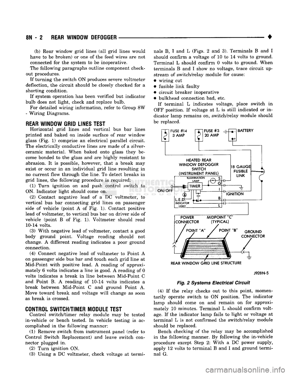
grid lines, the following procedure is required: (1) Turn ignition on and push control switch to
ON. Indicator light should come on. (2) Contact negative lead of a DC voltmeter, to
vertical bus bar connecting grid lines on passenger side of vehicle (point A of Fig. 1). Contact positive
lead of voltmeter, to vertical bus bar on driver side of
vehicle (point B of Fig. 1). Voltmeter should read 10-14 volts. (3) With negative lead of voltmeter, contact a good
body ground point. Voltage reading should not change. A different reading indicates a poor ground connection. (4) Connect negative lead of voltmeter to Point A
on passenger side bus bar and touch each grid line at
Mid-Point with positive lead. A reading of approxi mately 6 volts indicates a line is good. A reading of 0
volts indicates a break in line between Mid-Point C and Point B. A reading of 10-14 volts indicates a
break between Mid-Point C and ground Point A. Move toward break and voltage will change as soon as break is crossed.
CONTROL SWITCH/TIMER MODULE TEST
Control switch/timer relay module may be tested
in-vehicle or bench tested. In vehicle testing is ac
complished in the following manner: (1) Remove switch from instrument panel (refer to
Control Switch Replacement) and leave switch con
nector plugged in. (2) Turn ignition ON.
(3) Using a DC voltmeter, check voltage at termi nals B, I and L (Figs. 2 and 3). Terminals B and I
should confirm a voltage of 10 to 14 volts to ground.
Terminal L should confirm 0 volts to ground. When terminals B and I show no voltage, trace circuit up
stream of switch/relay module for cause:
• wiring cut
• fusible link faulty
• circuit breaker inoperative
• bulkhead connection bad, etc. If terminal L indicates voltage, place switch in
OFF position. If voltage at L is still indicated or in
dicator lamp remains on, switch/relay module should
be replaced.
"XI
FUSE
#14
rr~
P 3
AAAP
P
FUSE
#3
20
AAAP
BATTERY
HEATED
REAR
WINDOW
DEFOGGER
SWITCH
(INSTRUMENT
PANEL)
ON/OFF
ILLUMINATION
LAMP
fez TIMER
L.E.I
INDICATOR
LIGHT
-©-
18
GAUGE
FUSIBLE
LINK
IGNITION POWER
MIDPOINT
"C"
CONNECTOR (TYPICAL)
POINT
"A"
POINT
"B"
GROUND
CONNECTOR
REAR
WINDOW
GRID
LINE
STRUCTURE
Fig.
2
Systems
Electrical Circuit
J928N-5
(4) If the relay checks out to this point, momen
tarily operate switch to ON position. The indicator lamp should come on and remain on for approxi
mately 10 minutes. Terminal L should confirm volt
age.
If the indicator lamp fails to light or voltage at
terminal L is not confirmed the switch/relay module should be replaced.
Bench checking of the relay may be accomplished
in the following manner. By following the in-vehicle
procedure except Step 2: With a DC power supply, apply 12 volts to terminal B and I and ground termi
nal G.
Page 464 of 1502

•
POWER
WINDOWS
8S - 3
FROM PIN
SIDE
OF
SWITCH
MASTER
WINDOW
LIFT
SWITCH
SWITCH
POSITION CONTINUITY
BETWEEN
OFF
PINS
1 & 2
PINS
2 & 3
PINS
2 &4
PINS
2 & 6
DRIVER'S
MP
PINS
3 & 5
PINS
2 & 6
PASSENGER'S
PINS
1 & 5
PINS
2 &4
DRIVER'S
PINS
5 & 6
PINS
2 & 3
TOWN
PASSENGER'S
PINS
1 & 2
PINS
4 & 5 898S-11
Fig.
1 Master Window
Lift
Switch
Continuity
(b) Likewise, motor connected to DOWN direc
tion rotation, no movement will be observed if win
dow is already in full down position.
PIN IDENTIFICATION SHOWN
FROM
PIN
SIDE
OF
SWITCH
SWITCH CONTINUITY
POSITION
BETWEEN
PINS
1 & 4
OFF
PINS
2 & 5
PINS
3 & 4
UP
PINS
2 & 5
PINS
2 & 3
DOWN
PINS
1 & 4
898S-12
Fig.
2
Passenger's Door
Mounted
Switch
Continuity
(4) Reverse battery leads (opposite to steps 1 and
2) and window should now move. If window does not
move, remove motor. Refer to Service Procedures for
motor removal from vehicle for bench test.
If window moved completely up or down, motor
should be reversed one more time (reverse leads from
step 4) to complete a full window travel inspection.
SERVICE
PROCEDURES
GEAR
AND PINION
REPLACEMENT
AND
LUBRICATION
If gear and pinion assembly are replaced in gear
box, lubrication of gear box, gear pinion and seal is necessary. In the event there is no lubricant in gear box, fill
with MOPAR, multi-mileage lubricant or equivalent. Apply a liberal amount of lubricant to inside area of seal and sealing surface at center area of gear and
pinion coupling. Also lubricate center housing shaft and worm gear.
REGULATOR
AND
MOTOR
ASSEMBLY
REMOVAL To repair or inspect the entire electric window reg
ulator, remove from door as follows: (1) Remove remote control handle (Fig. 3).
(2) Remove power window/lock switch by inserting
a standard blade screwdriver into notch on forward
end of switch housing. Push screwdriver to depress
locking tab. Pull bezel out and forward to remove
from door panel.
(3) Remove screws at bottom front and rear of trim
panel.
(4) Remove screw behind remote handle.
(5)
Using a device such as a trim stick, pry trim
panel away from door around perimeter and remove
trim panel. (6) Roll door watershield away from bottom of door
to reveal inside panel access opening. (7) Remove speaker if equipped.
(8) Lower glass to full down position.
(9) Disconnect wiring connectors from motor.
Page 472 of 1502
-
CHIME/BUZZER WARNING SYSTEMS
8U - 1
CHIME/BUZZER
WARNING SYSTEMS
CONTENTS
page
DIAGNOSIS
GENERAL
INFORMATION
page
1
KEY-IN SWITCH REPLACEMENT
3
1
OPERATION
1
GENERAL
INFORMATION
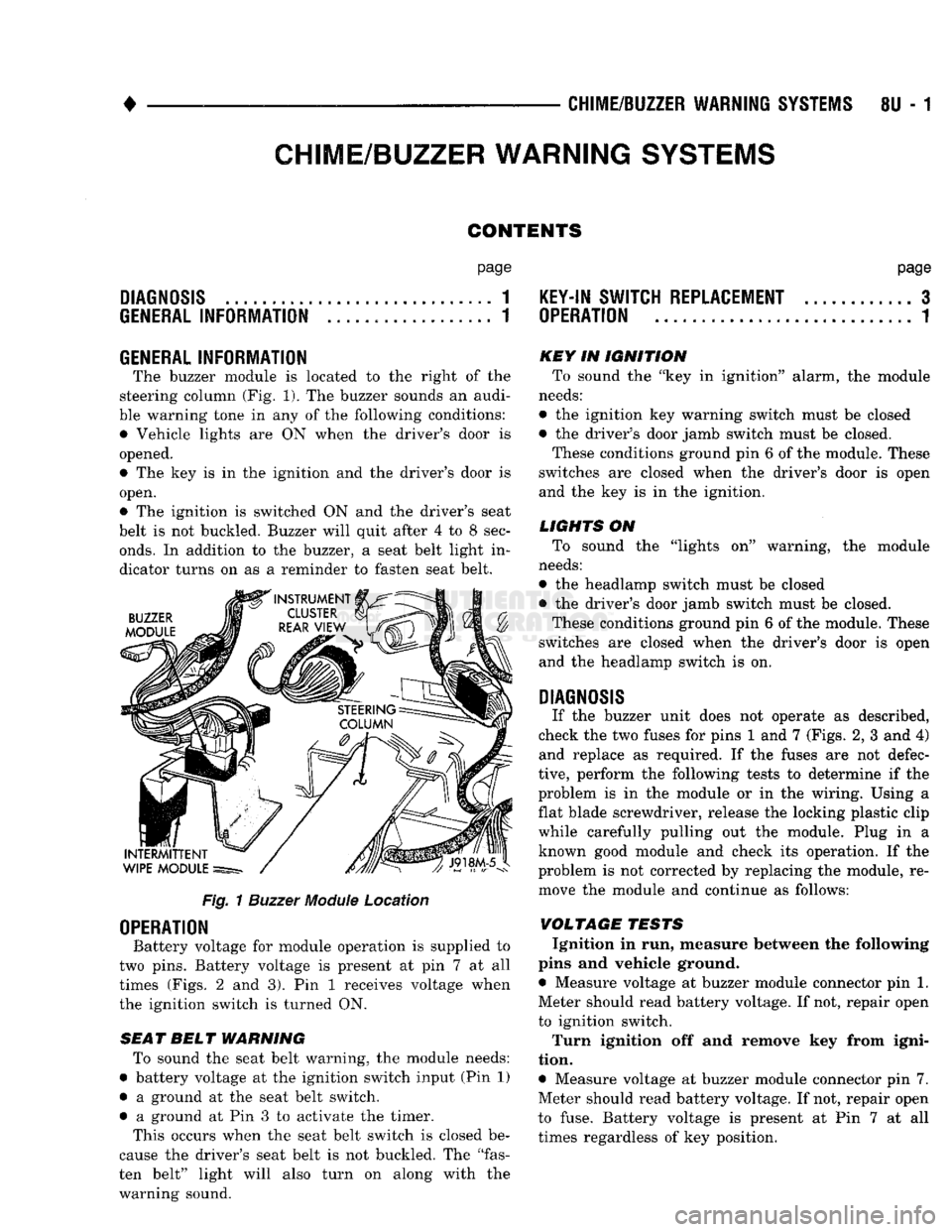
The buzzer module is located to the right of the
steering column (Fig. 1). The buzzer sounds an audi
ble warning tone in any of the following conditions: • Vehicle lights are ON when the driver's door is
opened.
• The key is in the ignition and the driver's door is
open. • The ignition is switched ON and the driver's seat
belt is not buckled. Buzzer will quit after 4 to 8 sec
onds.
In addition to the buzzer, a seat belt light in
dicator turns on as a reminder to fasten seat belt.
BUZZER
MODULE
INTERMITTENT
WIPE MODULE
Fig, 1 Buzzer Module Location
OPERATION
Battery voltage for module operation is supplied to
two pins. Battery voltage is present at pin 7 at all
times (Figs. 2 and 3). Pin 1 receives voltage when
the ignition switch is turned ON.
SEA T BELT WARNING To sound the seat belt warning, the module needs:
• battery voltage at the ignition switch input (Pin 1)
• a ground at the seat belt switch.
• a ground at Pin 3 to activate the timer. This occurs when the seat belt switch is closed be
cause the driver's seat belt is not buckled. The "fas
ten belt" light will also turn on along with the
warning sound. KEY IN IGNITION
To sound the "key in ignition" alarm, the module
needs:
• the ignition key warning switch must be closed
• the driver's door jamb switch must be closed. These conditions ground pin 6 of the module. These
switches are closed when the driver's door is open
and the key is in the ignition.
LIGHTS ON To sound the "lights on" warning, the module
needs:
• the headlamp switch must be closed
*> the driver's door jamb switch must be closed. These conditions ground pin 6 of the module. These
switches are closed when the driver's door is open
and the headlamp switch is on.
DIAGNOSIS
If the buzzer unit does not operate as described,
check the two fuses for pins 1 and 7 (Figs. 2, 3 and 4) and replace as required. If the fuses are not defec
tive,
perform the following tests to determine if the
problem is in the module or in the wiring. Using a flat blade screwdriver, release the locking plastic clip
while carefully pulling out the module. Plug in a known good module and check its operation. If the
problem is not corrected by replacing the module, re move the module and continue as follows:
VOLTAGE TESTS Ignition in run, measure between the following
pins and vehicle ground.
• Measure voltage at buzzer module connector pin 1.
Meter should read battery voltage. If not, repair open
to ignition switch.
Turn ignition off and remove key from igni
tion.
• Measure voltage at buzzer module connector pin 7.
Meter should read battery voltage. If not, repair open
to fuse. Battery voltage is present at Pin 7 at all
times regardless of key position.
Page 474 of 1502
•
CHIME/BUZZER
WARNING
SYSTEMS
8U - 3
KEY-IN
SWITCH REPLACEMENT
REMOVAL
(1) Disconnect negative cable from battery.
(2) Tilt column only—remove tilt lever (counter
clockwise).
(3) Carefully remove both upper and lower steer
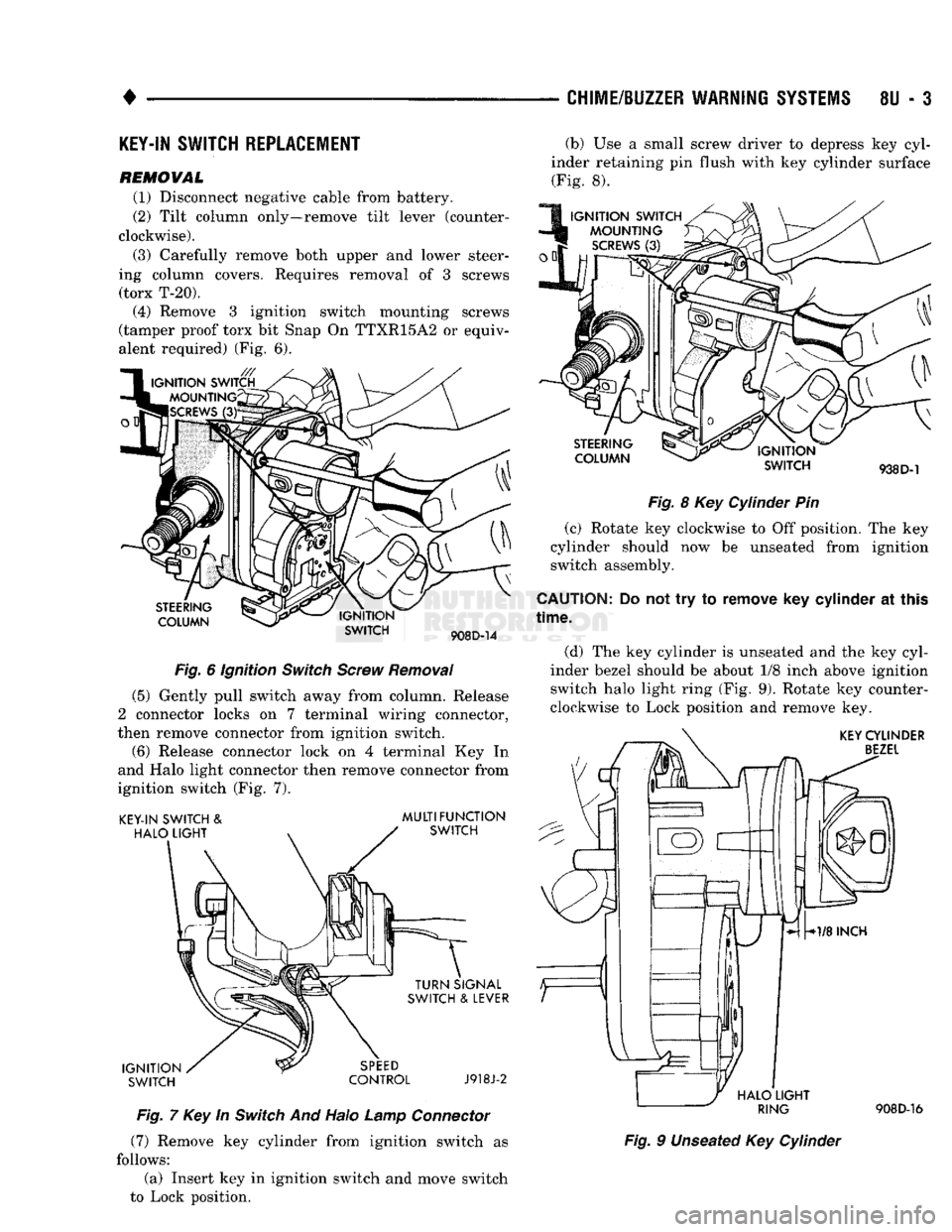
ing column covers. Requires removal of 3 screws (torx T-20). (4) Remove 3 ignition switch mounting screws
(tamper proof torx bit Snap On TTXR15A2 or equiv
alent required) (Fig. 6).
STEERING
COLUMN IGNITION
SWITCH
908D-14
Fig.
6 Ignition
Switch
Screw
Removal
(5) Gently pull switch away from column. Release
2 connector locks on 7 terminal wiring connector,
then remove connector from ignition switch.
(6) Release connector lock on 4 terminal Key In
and Halo light connector then remove connector from
ignition switch (Fig. 7).
KEY-IN SWITCH
&
HALO
LIGHT
MULTIFUNCTION
SWITCH
IGNITION SWITCH TURN SIGNAL
SWITCH
&
LEVER
SPEED
CONTROL
J918J-2
Fig.
7 Key In
Switch
And Halo
Lamp
Connector
(7) Remove key cylinder from ignition switch as
follows:
(a) Insert key in ignition switch and move switch
to Lock position. (b) Use a small screw driver to depress key cyl
inder retaining pin flush with key cylinder surface (Fig. 8).
IGNITION SWITCH MOUNTING
SCREWS
(3)
STEERING
COLUMN IGNITION
SWITCH
938 D-1
Fig.
8 Key Cylinder Pin
(c) Rotate key clockwise to Off position. The key
cylinder should now be unseated from ignition
switch assembly.
CAUTION:
Do not try to remove key cylinder at this
time.
(d) The key cylinder is unseated and the key cyl
inder bezel should be about 1/8 inch above ignition
switch halo light ring (Fig. 9). Rotate key counter
clockwise to Lock position and remove key.
KEY
CYLINDER
BEZEL
HALO
LIGHT
RING
908D-16
Fig.
9 Unseated Key Cylinder
Page 478 of 1502
•
WIRING
DIAGRAMS
8W - 3 fer to a components name in the index if you are
unclear as to what a system may be called.
Diagram pages are arranged starting with the bat
tery and fuses. Then working into charging, starting, and ignition systems. After this they start at the
front of the vehicle and work to rear of the vehicle.
The diagrams end with connector identification
pages.
COMPONENT
IDENTIFICATION
To find a components actual location on the vehicle
refer to the wiring and components section index. This section shows the wire harness routing and the compo
nents location in the vehicle. When using this section
refer to the wiring diagrams for the general location of
the component. Then use the component identification index to locate the proper figure number.
SPLICE
LOCATIONS
Splices are indicated in the wiring diagrams by a
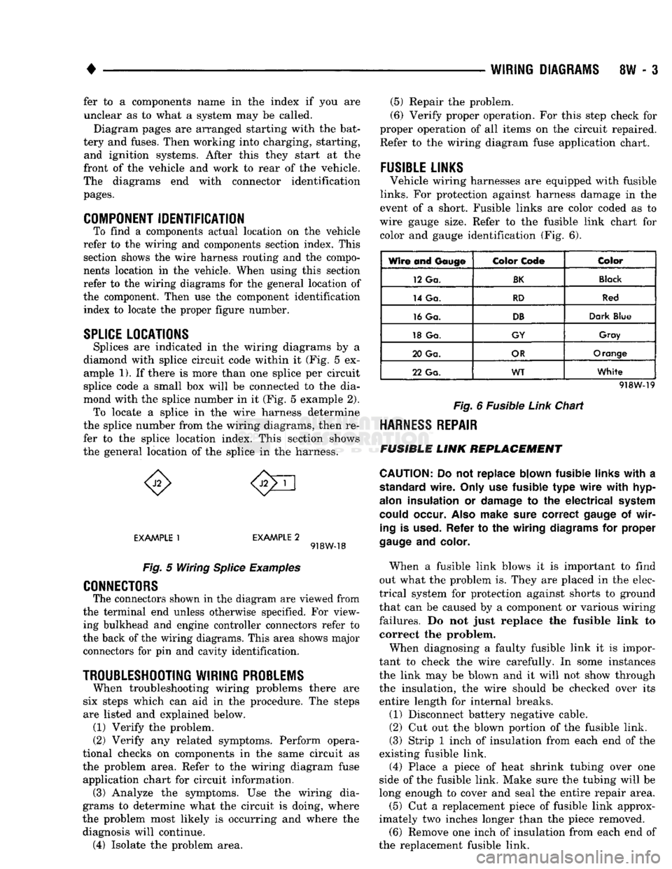
diamond with splice circuit code within it (Fig. 5 ex ample 1). If there is more than one splice per circuit
splice code a small box will be connected to the dia
mond with the splice number in it (Fig. 5 example 2). To locate a splice in the wire harness determine
the splice number from the wiring diagrams, then re
fer to the splice location index. This section shows
the general location of the splice in the harness.
EXAMPLE
1
EXAMPLE
2 918W-18
Fig.
5 Wiring
Splice
Examples
CONNECTORS
The connectors shown in the diagram are viewed from
the terminal end unless otherwise specified. For view ing bulkhead and engine controller connectors refer to
the back of the wiring diagrams. This area shows major connectors for pin and cavity identification.
TROUBLESHOOTING
WIRING
PROBLEMS
When troubleshooting wiring problems there are
six steps which can aid in the procedure. The steps
are listed and explained below. (1) Verify the problem.
(2) Verify any related symptoms. Perform opera
tional checks on components in the same circuit as the problem area. Refer to the wiring diagram fuse
application chart for circuit information. (3) Analyze the symptoms. Use the wiring dia
grams to determine what the circuit is doing, where
the problem most likely is occurring and where the diagnosis will continue. (4) Isolate the problem area. (5) Repair the problem.
(6) Verify proper operation. For this step check for
proper operation of all items on the circuit repaired. Refer to the wiring diagram fuse application chart.
FUSIBLE
LINKS
Vehicle wiring harnesses are equipped with fusible
links.
For protection against harness damage in the
event of a short. Fusible links are color coded as to
wire gauge size. Refer to the fusible link chart for color and gauge identification (Fig. 6).
Wire and
Gauge
Color
Code
Color
12 Ga.
BK
Black
14 Ga.
RD
Red
16 Ga.
DB
Dark
Blue
18 Ga.
GY
Gray
20 Ga.
OR
Orange
22 Ga.
WT
White
918W-19
Fig.
6 Fusible
Link
Chart
HARNESS
REPAIR
FUSIBLE
LINK
REPLACEMENT
CAUTION:
Do not replace blown fusible
links
with
a
standard
wire.
Only
use fusible type
wire
with
hyp-
alon
insulation or
damage
to the electrical
system
could
occur.
Also
make
sure
correct
gauge
of
wir
ing
is
used.
Refer to the wiring
diagrams
for proper
gauge
and
color.
When a fusible link blows it is important to find
out what the problem is. They are placed in the elec
trical system for protection against shorts to ground
that can be caused by a component or various wiring
failures. Do not just replace the fusible link to correct the problem.
When diagnosing a faulty fusible link it is impor
tant to check the wire carefully. In some instances
the link may be blown and it will not show through the insulation, the wire should be checked over its
entire length for internal breaks.
(1) Disconnect battery negative cable.
(2) Cut out the blown portion of the fusible link.
(3) Strip 1 inch of insulation from each end of the
existing fusible link.
(4) Place a piece of heat shrink tubing over one
side of the fusible link. Make sure the tubing will be
long enough to cover and seal the entire repair area.
(5) Cut a replacement piece of fusible link approx
imately two inches longer than the piece removed. (6) Remove one inch of insulation from each end of
the replacement fusible link.
Page 479 of 1502
8W
- 4
WIRING
DIAGRAMS
(7) Spread
the
strands
of
wire apart
on
each
of the
exposed wires
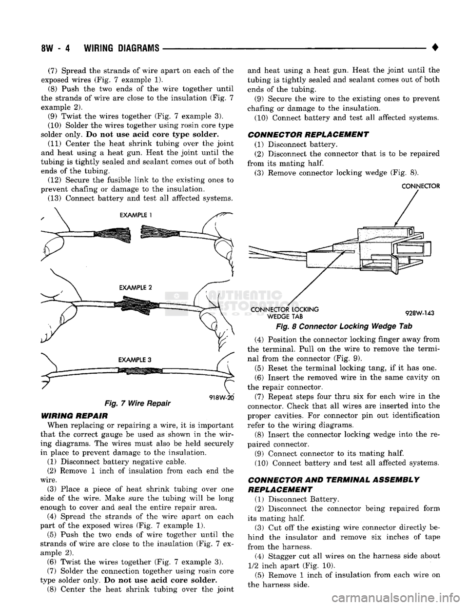
(Fig. 7
example
1).
(8) Push
the two
ends
of the
wire together until
the strands
of
wire
are
close
to the
insulation
(Fig. 7
example
2).
(9) Twist
the
wires together
(Fig. 7
example
3).
(10) Solder
the
wires together using rosin core type
solder only.
Do not use
acid core type solder.
(11) Center
the
heat shrink tubing over
the
joint
and heat using
a
heat
gun.
Heat
the
joint until
the
tubing
is
tightly sealed
and
sealant comes
out of
both ends
of the
tubing. (12) Secure
the
fusible link
to the
existing ones
to
prevent chafing
or
damage
to the
insulation.
(13) Connect battery
and
test
all
affected systems.
Fig.
7
Wire Repair
918W-20
WIRING REPAIR When replacing
or
repairing
a
wire,
it is
important
that
the
correct gauge
be
used
as
shown
in the
wir ing diagrams.
The
wires must also
be
held securely
in place
to
prevent damage
to the
insulation.
(1) Disconnect battery negative cable.
(2) Remove
1
inch
of
insulation from each
end the
wire.
(3) Place
a
piece
of
heat shrink tubing over
one
side
of the
wire. Make sure
the
tubing will
be
long
enough
to
cover
and
seal
the
entire repair area.
(4) Spread
the
strands
of the
wire apart
on
each
part
of the
exposed wires
(Fig. 7
example
1).
(5)
Push
the two
ends
of
wire together until
the
strands
of
wire
are
close
to the
insulation
(Fig. 7 ex
ample
2).
(6) Twist
the
wires together
(Fig. 7
example
3).
(7) Solder
the
connection together using rosin core
type solder only.
Do not use
acid core solder.
(8)
Center
the
heat shrink tubing over
the
joint and heat using
a
heat
gun.
Heat
the
joint until
the
tubing
is
tightly sealed
and
sealant comes
out of
both
ends
of the
tubing.
(9) Secure
the
wire
to the
existing ones
to
prevent
chafing
or
damage
to the
insulation.
(10) Connect battery
and
test
all
affected systems.
CONNECTOR REPLACEMENT (1) Disconnect battery.
(2) Disconnect
the
connector that
is to be
repaired
from
its
mating
half.
(3) Remove connector locking wedge
(Fig. 8).
CONNECTOR
CONNECTOR
LOCKING
WEDGE
TAB
928W-143
Fig.
8
Connector Locking Wedge
Tab
(4) Position
the
connector locking finger away from
the terminal. Pull
on the
wire
to
remove
the
termi nal from
the
connector
(Fig. 9).
(5) Reset
the
terminal locking tang,
if it has one.
(6) Insert
the
removed wire
in the
same cavity
on
the repair connector.
(7) Repeat steps four thru
six for
each wire
in the
connector. Check that
all
wires
are
inserted into
the
proper cavities.
For
connector
pin out
identification refer
to the
wiring diagrams.
(8) Insert
the
connector locking wedge into
the re
paired connector.
(9) Connect connector
to its
mating
half.
(10) Connect battery
and
test
all
affected systems.
CONNECTOR
AND
TERMINAL ASSEMBLY
REPLACEMENT
(1) Disconnect Battery.
(2) Disconnect
the
connector being repaired form
its mating
half.
(3)
Cut off the
existing wire connector directly
be
hind
the
insulator
and
remove
six
inches
of
tape
from
the
harness.
(4) Stagger
cut all
wires
on the
harness side about
1/2
inch apart
(Fig. 10).
(5) Remove
1
inch
of
insulation from each wire
on
the harness side.