brake fluid DODGE TRUCK 1993 Service Owner's Manual
[x] Cancel search | Manufacturer: DODGE, Model Year: 1993, Model line: TRUCK, Model: DODGE TRUCK 1993Pages: 1502, PDF Size: 80.97 MB
Page 195 of 1502
i - 8
BRAKES
•
BRAKE
SHOE'S
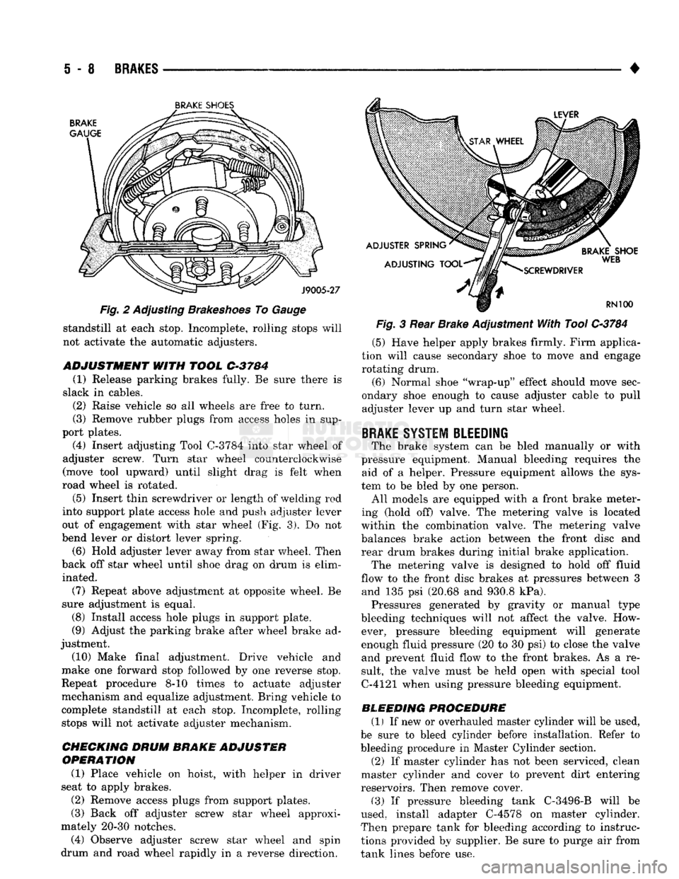
Fig. 2 Adjusting Brakeshoes To Gauge standstill at each stop. Incomplete, rolling stops will
not activate the automatic adjusters.
ADJUSTMENT
WITH
TOOL
C-3784
(1) Release parking brakes fully. Be sure there is
slack in cables. (2) Raise vehicle so all wheels are free to turn.
(3) Remove rubber plugs from access holes in sup
port plates. (4) Insert adjusting Tool
0-3784
into star wheel of
adjuster screw. Turn star wheel counterclockwise
(move tool upward) until slight drag is felt when
road wheel is rotated.
(5)
Insert thin screwdriver or length of welding rod
into support plate access hole and push adjuster lever
out of engagement with star wheel (Fig. 3). Do not
bend lever or distort lever spring.
(6) Hold adjuster lever away from star wheel. Then
back off star wheel until shoe drag on drum is elim inated.
(7) Repeat above adjustment at opposite wheel. Be
sure adjustment is equal. (8) Install access hole plugs in support plate.
(9) Adjust the parking brake after wheel brake ad
justment.
(10) Make final adjustment. Drive vehicle and
make one forward stop followed by one reverse stop.
Repeat procedure 8-10 times to actuate adjuster
mechanism and equalize adjustment. Bring vehicle to
complete standstill at each stop. Incomplete, rolling stops will not activate adjuster mechanism.
CHECKING DRUM
BRAKE ADJUSTER
OPERATION
(1) Place vehicle on hoist, with helper in driver
seat to apply brakes.
(2) Remove access plugs from support plates.
(3) Back off adjuster screw star wheel approxi
mately 20-30 notches. (4) Observe adjuster screw star wheel and spin
drum and road wheel rapidly in a reverse direction. Fig. 3 Rear Brake Adjustment With Tool
C-3784
(5) Have helper apply brakes firmly. Firm applica
tion will cause secondary shoe to move and engage rotating drum.
(6) Normal shoe "wrap-up" effect should move sec
ondary shoe enough to cause adjuster cable to pull adjuster lever up and turn star wheel.
BRAKE
SYSTEM BLEEDING
The brake system can be bled manually or with
pressure equipment. Manual bleeding requires the aid of a helper. Pressure equipment allows the sys
tem to be bled by one person. All models are equipped with a front brake meter
ing (hold off) valve. The metering valve is located
within the combination valve. The metering valve balances brake action between the front disc and
rear drum brakes during initial brake application. The metering valve is designed to hold off fluid
flow to the front disc brakes at pressures between 3 and 135 psi (20.68 and 930.8 kPa). Pressures generated by gravity or manual type
bleeding techniques will not affect the valve. How ever, pressure bleeding equipment will generate
enough fluid pressure (20 to 30 psi) to close the valve and prevent fluid flow to the front brakes. As a re
sult, the valve must be held open with special tool
C-4121 when using pressure bleeding equipment.
BLEEDING PROCEDURE (1) If new or overhauled master cylinder will be used,
be sure to bleed cylinder before installation. Refer to
bleeding procedure in Master Cylinder section. (2) If master cylinder has not been serviced, clean
master cylinder and cover to prevent dirt entering
reservoirs. Then remove cover.
(3) If pressure bleeding tank C-3496-B will be
used, install adapter C-4578 on master cylinder.
Then prepare tank for bleeding according to instruc
tions provided by supplier. Be sure to purge air from
tank lines before use.
Page 196 of 1502
BRAKES
i - 9
Fig.
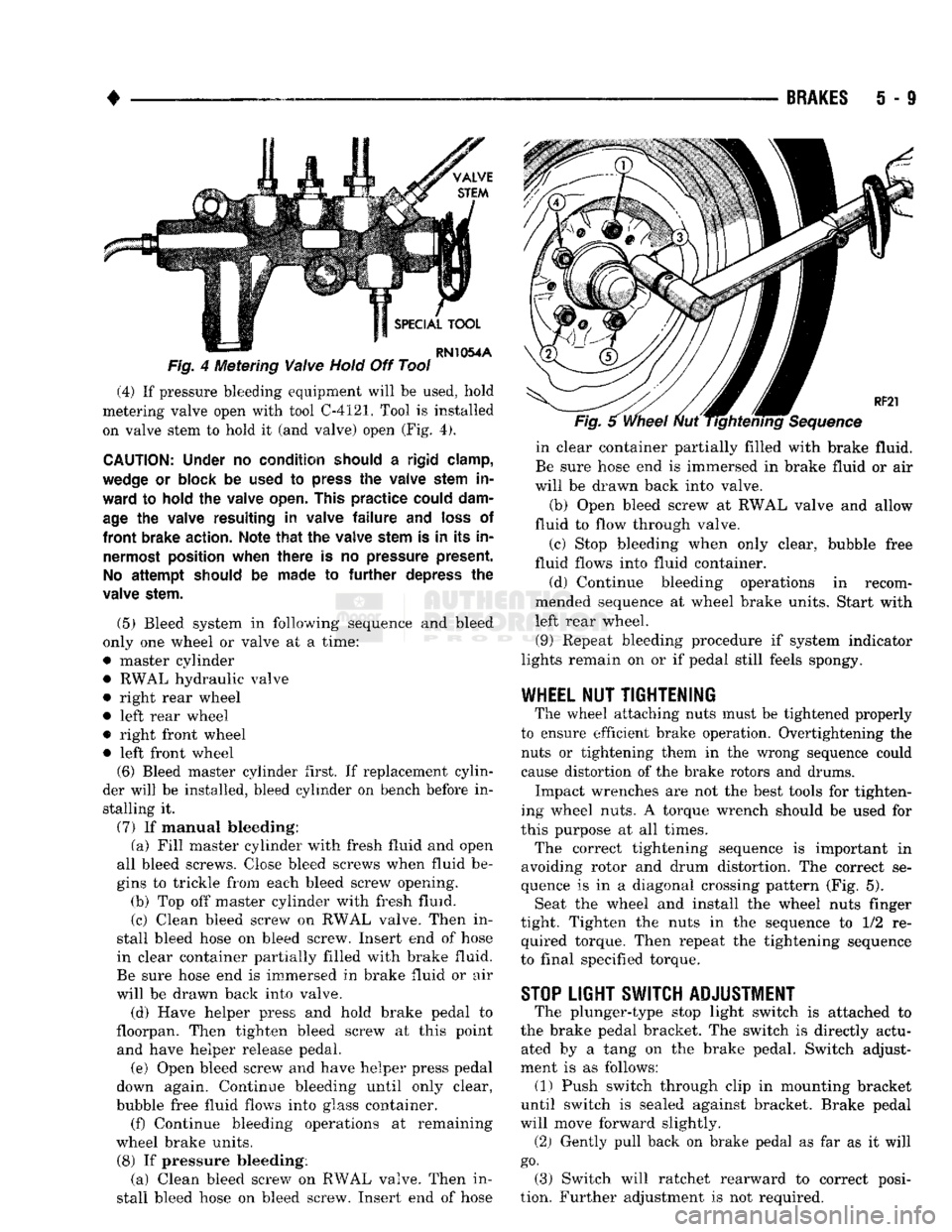
4 Metering
Valve
Hold
Off Tool (4) If pressure bleeding equipment will be used, hold
metering valve open with tool C-4121. Tool is installed on valve stem to hold it (and valve) open (Fig. 4).
CAUTION:
Under
no
condition should
a
rigid clamp,
wedge
or
block
be
used
to
press
the
valve stem
in
ward
to
hold
the
valve open. This
practice
could dam
age
the
valve resulting
in
valve
failure and
loss
of
front
brake action. Note
that the
valve stem
is in its in
nermost position when
there
is no
pressure present.
No
attempt
should
be
made
to further
depress
the
valve stem.
(5) Bleed system in following sequence and bleed
only one wheel or valve at a time:
• master cylinder • RWAL hydraulic valve
• right rear wheel
• left rear wheel
• right front wheel • left front wheel (6) Bleed master cylinder first. If replacement cylin
der will be installed, bleed cylinder on bench before in stalling it.
(7) If manual bleeding: (a) Fill master cylinder with fresh fluid and open
all bleed screws. Close bleed screws when fluid be
gins to trickle from each bleed screw opening. (b) Top off master cylinder with fresh fluid.
(c) Clean bleed screw on RWAL valve. Then in
stall bleed hose on bleed screw. Insert end of hose
in clear container partially filled with brake fluid.
Be sure hose end is immersed in brake fluid or air
will be drawn back into valve.
(d) Have helper press and hold brake pedal to
floorpan. Then tighten bleed screw at this point and have helper release pedal.
(e) Open bleed screw and have helper press pedal
down again. Continue bleeding until only clear,
bubble free fluid flows into glass container. (f) Continue bleeding operations at remaining
wheel brake units.
(8) If pressure bleeding: (a) Clean bleed screw on RWAL valve. Then in
stall bleed hose on bleed screw. Insert end of hose in clear container partially filled with brake fluid.
Be sure hose end is immersed in brake fluid or air
will be drawn back into valve.
(b) Open bleed screw at RWAL valve and allow
fluid to flow through valve.
(c) Stop bleeding when only clear, bubble free
fluid flows into fluid container.
(d) Continue bleeding operations in recom
mended sequence at wheel brake units. Start with
left rear wheel.
(9) Repeat bleeding procedure if system indicator
lights remain on or if pedal still feels spongy.
WHEEL
NUT
TIGHTENING
The wheel attaching nuts must be tightened properly
to ensure efficient brake operation. Overtightening the nuts or tightening them in the wrong sequence could
cause distortion of the brake rotors and drums.
Impact wrenches are not the best tools for tighten
ing wheel nuts. A torque wrench should be used for
this purpose at all times.
The correct tightening sequence is important in
avoiding rotor and drum distortion. The correct se
quence is in a diagonal crossing pattern (Fig. 5). Seat the wheel and install the wheel nuts finger
tight. Tighten the nuts in the sequence to 1/2 re quired torque. Then repeat the tightening sequence
to final specified torque.
STOP
LIGHT SWITCH ADJUSTMENT
The plunger-type stop light switch is attached to
the brake pedal bracket. The switch is directly actu ated by a tang on the brake pedal. Switch adjust
ment is as follows: (1) Push switch through clip in mounting bracket
until switch is sealed against bracket. Brake pedal
will move forward slightly.
(2) Gently pull back on brake pedal as far as it will
go.
(3) Switch will ratchet rearward to correct posi
tion. Further adjustment is not required.
Page 197 of 1502
S
- 10
BRAKES
•
MASTER CYLINDER—COMBINATION
VALVE—BRAKE
LINES
INDEX
page
Bleeding
New
or
Overhauled Master Cylinder
. . . 12
Brake
Lines
and
Hoses
13
Combination Valve Operation
13
Combination Valve Removal/Installation
........
13
Combination Valve Testing
.................
13
page
General
Information
. 10
Master
Cylinder
Installation
12
Master
Cylinder Removal
10
Master
Cylinder Service—Integral Cylinder
11
Master
Cylinder Service—Two-Section Cylinder
. . 11
GENERAL
INFORMATION
Two types
of
master cylinder
are
used
on AD
mod
els.
A
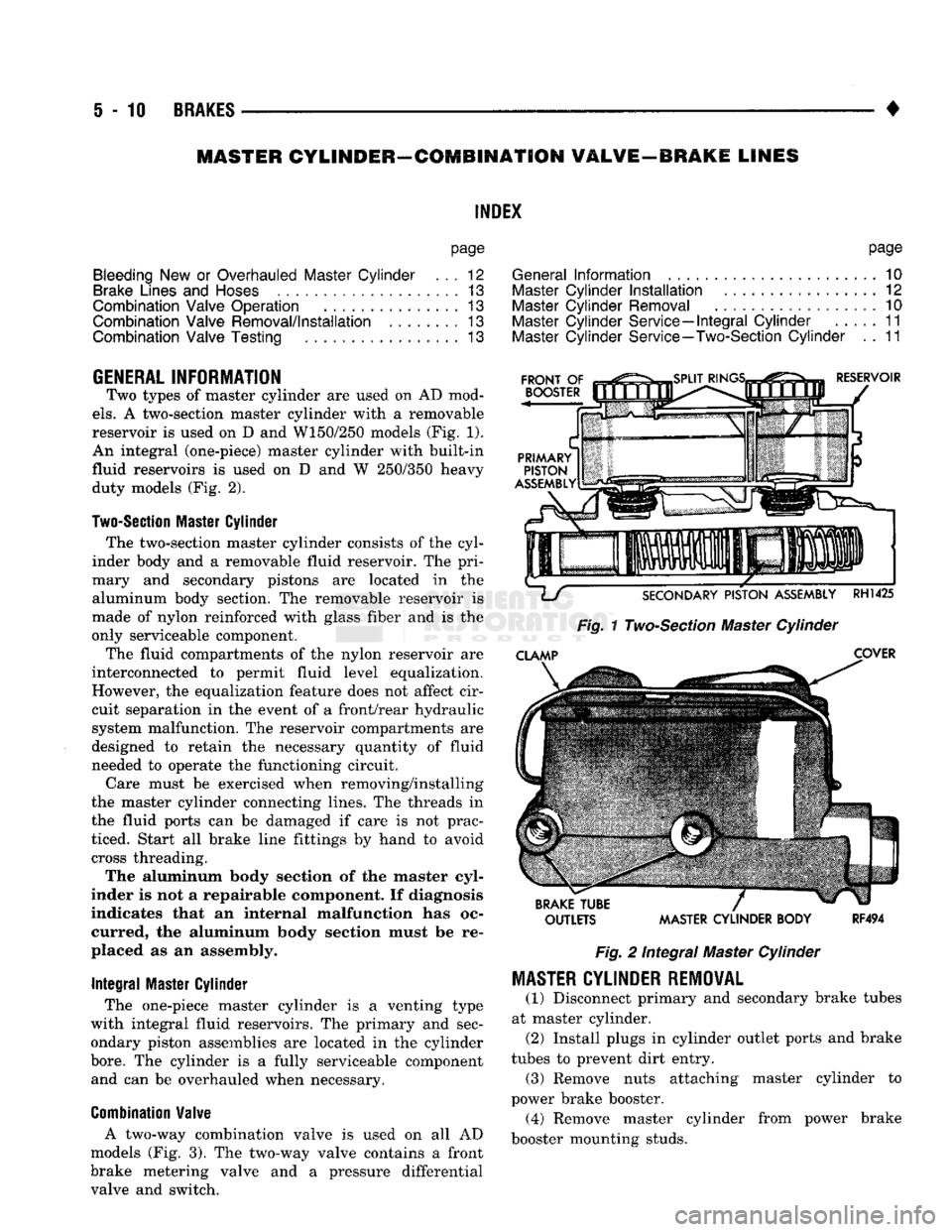
two-section master cylinder with
a
removable
reservoir
is
used
on D and
W150/250 models
(Fig.
1).
An integral (one-piece) master cylinder with built-in
fluid reservoirs
is
used
on D and W
250/350 heavy duty models
(Fig.
2).
Two-Section
Master
Cylinder
The two-section master cylinder consists
of
the
cyl
inder body
and a
removable fluid reservoir.
The
pri
mary
and
secondary pistons
are
located
in the
aluminum body section.
The
removable reservoir
is
made
of
nylon reinforced with glass fiber
and is the
only serviceable component.
The fluid compartments
of the
nylon reservoir
are
interconnected
to
permit fluid level equalization.
However,
the
equalization feature does
not
affect cir
cuit separation
in the
event
of a
front/rear hydraulic
system malfunction.
The
reservoir compartments
are
designed
to
retain
the
necessary quantity
of
fluid
needed
to
operate
the
functioning circuit.
Care must
be
exercised when removing/installing
the master cylinder connecting lines.
The
threads
in
the fluid ports
can be
damaged
if
care
is not
prac
ticed. Start
all
brake line fittings
by
hand
to
avoid cross threading.
The aluminum body section
of the
master cyl
inder
is not a
repairable component.
If
diagnosis
indicates that
an
internal malfunction
has oc
curred,
the
aluminum body section must
be re
placed
as an
assembly.
Integral
Master Cylinder
The one-piece master cylinder
is a
venting type
with integral fluid reservoirs.
The
primary
and
sec
ondary piston assemblies
are
located
in the
cylinder
bore.
The
cylinder
is a
fully serviceable component and
can be
overhauled when necessary.
Combination
Valve
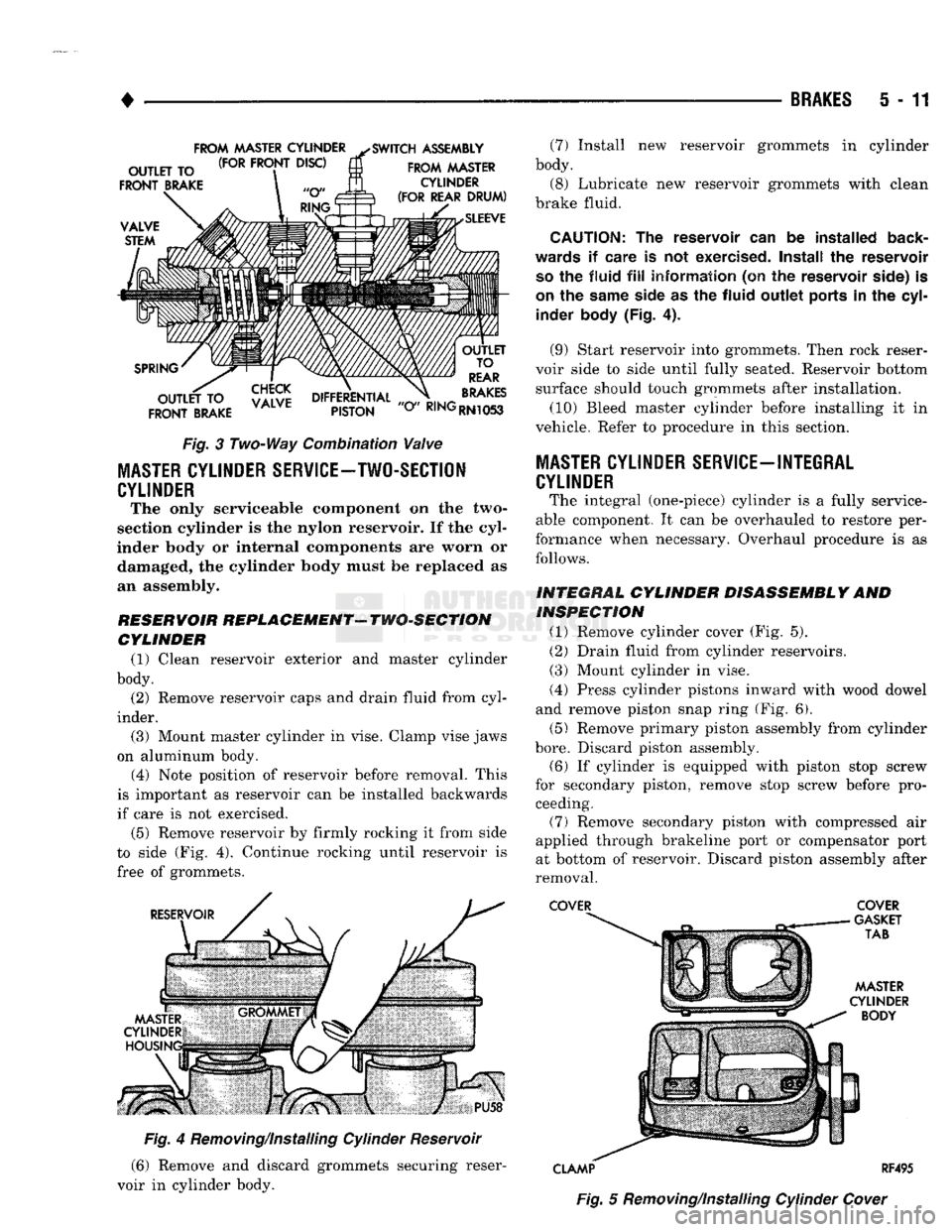
A two-way combination valve
is
used
on all AD
models
(Fig.
3). The
two-way valve contains
a
front
brake metering valve
and a
pressure differential valve
and
switch.
OUTLETS MASTER CYLINDER BODY
RF494
Fig.
2
Integral Master Cylinder
MASTER
CYLINDER REMOVAL
(1) Disconnect primary
and
secondary brake tubes
at master cylinder. (2) Install plugs
in
cylinder outlet ports
and
brake
tubes
to
prevent dirt entry. (3) Remove nuts attaching master cylinder
to
power brake booster. (4) Remove master cylinder from power brake
booster mounting studs.
Page 198 of 1502
•
BRAKES
5 - 11
FROM
MASTER CYLINDER
^SWITCH
ASSEMBLY
Fig.
3 Two-Way Combination
Valve
MASTER
CYLINDER SERVICE-TWO-SECTION
CYLINDER
The only serviceable component on the two-
section cylinder is the nylon reservoir. If the cyl
inder body or internal components are worn or damaged, the cylinder body must be replaced as
an assembly.
RESERVOIR REPLACEMENT- TWO-SECTION CYLINDER (1) Clean reservoir exterior and master cylinder
body. (2) Remove reservoir caps and drain fluid from cyl
inder. (3) Mount master cylinder in vise. Clamp vise jaws
on aluminum body.
(4) Note position of reservoir before removal. This
is important as reservoir can be installed backwards
if care is not exercised.
(5) Remove reservoir by firmly rocking it from side
to side (Fig. 4). Continue rocking until reservoir is
free of grommets.
Fig.
4 Removing/Installing Cylinder Reservoir
(6) Remove and discard grommets securing reser
voir in cylinder body. (7) Install new reservoir grommets in cylinder
body. (8) Lubricate new reservoir grommets with clean
brake fluid.
CAUTION:
The reservoir can be installed
back
wards
if care is not
exercised.
Install the reservoir
so
the fluid
fill
information (on the reservoir
side)
is
on
the
same
side
as the fluid outlet
ports
in the
cyl
inder
body
(Fig. 4).
(9) Start reservoir into grommets. Then rock reser
voir side to side until fully seated. Reservoir bottom surface should touch grommets after installation.
(10) Bleed master cylinder before installing it in
vehicle. Refer to procedure in this section.
MASTER CYLINDER SERVICE-INTEGRAL
CYLINDER
The integral (one-piece) cylinder is a fully service
able component. It can be overhauled to restore per
formance when necessary. Overhaul procedure is as follows.
INTEGRAL CYLINDER DISASSEMBLY AND INSPECTION
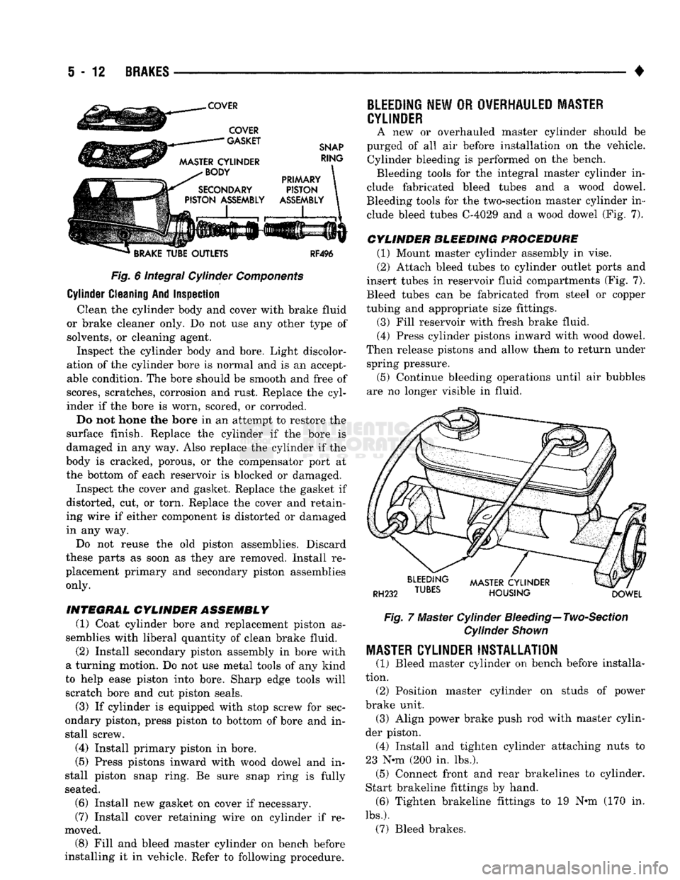
(1) Remove cylinder cover (Fig. 5). (2) Drain fluid from cylinder reservoirs.
(3) Mount cylinder in vise.
(4) Press cylinder pistons inward with wood dowel
and remove piston snap ring (Fig. 6).
(5) Remove primary piston assembly from cylinder
bore.
Discard piston assembly.
(6) If cylinder is equipped with piston stop screw
for secondary piston, remove stop screw before pro ceeding. (7) Remove secondary piston with compressed air
applied through brakeline port or compensator port
at bottom of reservoir. Discard piston assembly after
removal.
COVER COVER
CLAMP RF495 Fig.
5 Removing/Installing Cylinder
Cover
Page 199 of 1502
i - 12
BRAKES
•
Fig.
6 integral Cylinder
Components
Cylinder Cleaning And Inspection Clean the cylinder body and cover with brake fluid
or brake cleaner only. Do not use any other type of solvents, or cleaning agent. Inspect the cylinder body and bore. Light discolor
ation of the cylinder bore is normal and is an accept
able condition. The bore should be smooth and free of
scores, scratches, corrosion and rust. Replace the cyl
inder if the bore is worn, scored, or corroded.
Do not hone the bore in an attempt to restore the
surface finish. Replace the cylinder if the bore is
damaged in any way. Also replace the cylinder if the
body is cracked, porous, or the compensator port at
the bottom of each reservoir is blocked or damaged.
Inspect the cover and gasket. Replace the gasket if
distorted, cut, or torn. Replace the cover and retain
ing wire if either component is distorted or damaged
in any way.
Do not reuse the old piston assemblies. Discard
these parts as soon as they are removed. Install re
placement primary and secondary piston assemblies
only.
INTEGRAL
CYLINDER ASSEMBLY
(1) Coat cylinder bore and replacement piston as
semblies with liberal quantity of clean brake fluid.
(2) Install secondary piston assembly in bore with
a turning motion. Do not use metal tools of any kind
to help ease piston into bore. Sharp edge tools will
scratch bore and cut piston seals.
(3) If cylinder is equipped with stop screw for sec
ondary piston, press piston to bottom of bore and in
stall screw.
(4) Install primary piston in bore.
(5) Press pistons inward with wood dowel and in
stall piston snap ring. Be sure snap ring is fully
seated.
(6) Install new gasket on cover if necessary.
(7) Install cover retaining wire on cylinder if re
moved. (8) Fill and bleed master cylinder on bench before
installing it in vehicle. Refer to following procedure.
BLEEDING
NEW
OR
OVERHAULED MASTER
CYLINDER
A new or overhauled master cylinder should be
purged of all air before installation on the vehicle. Cylinder bleeding is performed on the bench. Bleeding tools for the integral master cylinder in
clude fabricated bleed tubes and a wood dowel.
Bleeding tools for the two-section master cylinder in clude bleed tubes C-4029 and a wood dowel (Fig. 7).
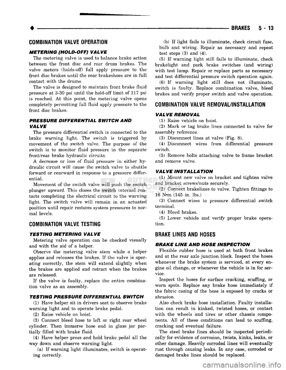
CYLINDER BLEEDING PROCEDURE
(1) Mount master cylinder assembly in vise.
(2) Attach bleed tubes to cylinder outlet ports and
insert tubes in reservoir fluid compartments (Fig. 7).
Bleed tubes can be fabricated from steel or copper
tubing and appropriate size fittings.
(3) Fill reservoir with fresh brake fluid. (4) Press cylinder pistons inward with wood dowel.
Then release pistons and allow them to return under spring pressure.
(5) Continue bleeding operations until air bubbles
are no longer visible in fluid.
Fig.
7 Master Cylinder
Bleeding—
Two-Section
Cylinder
Shown
MASTER
CYLINDER INSTALLATION
(1) Bleed master cylinder on bench before installa
tion. (2) Position master cylinder on studs of power
brake unit. (3) Align power brake push rod with master cylin
der piston. (4) Install and tighten cylinder attaching nuts to
23 N-m (200 in. lbs.). (5) Connect front and rear brakelines to cylinder.
Start brakeline fittings by hand. (6) Tighten brakeline fittings to 19 N«m (170 in.
lbs.).
(7) Bleed brakes.
Page 200 of 1502
•
BRAKES
5 - 13
COMBINATION VALVE OPERATION
METERING (HOLD-OFF) VALVE The metering valve is used to balance brake action
between the front disc and rear drum brakes. The
valve meters (holds-off) full apply pressure to the front disc brakes until the rear brakeshoes are in full
contact with the drums.
The valve is designed to maintain front brake fluid
pressure at 3-30 psi until the hold-off limit of 117 psi is reached. At this point, the metering valve opens completely permitting full fluid apply pressure to the
front disc brakes.
PRESSURE DIFFERENTIAL SWITCH AND VALVE The pressure differential switch is connected to the
brake warning light. The switch is triggered by movement of the switch valve. The purpose of the switch is to monitor fluid pressure in the separate
front/rear brake hydraulic circuits.
A decrease or loss of fluid pressure in either hy
draulic circuit will cause the switch valve to shuttle
forward or rearward in response to a pressure differ ential.
Movement of the switch valve will push the switch
plunger upward. This closes the switch internal con tacts completing the electrical circuit to the warning light. The switch valve will remain in an actuated
position until repair restores system pressures to nor mal levels.
COMBINATION VALVE TESTING
TESTING METERING VALVE Metering valve operation can be checked visually
and with the aid of a helper.
Observe the metering valve stem while a helper
applies and releases the brakes. If the valve is oper
ating correctly, the stem will extend slightly when
the brakes are applied and retract when the brakes are released.
If the valve is faulty, replace the entire combina
tion valve as an assembly.
TESTING PRESSURE DIFFERENTIAL SWITCH (1) Have helper sit in drivers seat to observe brake
warning light and to operate brake pedal.
(2) Raise vehicle on hoist.
(3) Connect bleed hose to left or right rear wheel
cylinder. Then immerse hose end in glass jar par
tially filled with brake fluid.
(4) Have helper press and hold brake pedal all the
way down and observe warning light.
(a) If warning light illuminates, switch is operat
ing correctly. (b) If light fails to illuminate, check circuit fuse,
bulb and wiring. Repair as necessary and repeat test steps (3) and (4). (5) If warning light still fails to illuminate, check
brakelight and park brake switches (and wiring) with test lamp. Repair or replace parts as necessary and test differential pressure switch operation again.
(6) If warning light still does not illuminate,
switch is faulty. Replace combination valve, bleed
brakes and verify proper switch and valve operation.
COMBINATION VALVE REMOVAL/INSTALLATION
VALVE REMOVAL (1) Raise vehicle on hoist.
(2) Mark or tag brake lines connected to valve for
assembly reference.
(3) Disconnect lines at valve (Fig. 8).
(4) Disconnect wires from differential pressure
switch.
(5) Remove bolts attaching valve to frame bracket
and remove valve.
VALVE INSTALLATION (1) Mount new valve on bracket and tighten valve
and bracket screws/nuts securely.
(2) Connect brakelines to valve. Tighten fittings to
16 N*m (145 in. lbs.)
(3) Connect wires to pressure differential switch
terminal. (4) Bleed brakes.
(5) Lower vehicle and verify proper brake opera
tion.
BRAKE
LINES AND
HOSES
BRAKE LINE AND HOSE INSPECTION Flexible rubber hose is used at both front brakes
and at the rear axle junction block. Inspect the hoses
whenever the brake system is serviced, at every en gine oil change, or whenever the vehicle is in for ser
vice.
Inspect the hoses for surface cracking, scuffing, or
worn spots. Replace any brake hose immediately if
the fabric casing of the hose is exposed by cracks or abrasion.
Also check brake hose installation. Faulty installa
tion can result in kinked, twisted hoses, or contact with the wheels and tires or other chassis compo
nents.
All of these conditions can lead to scuffing,
cracking and eventual failure.
The steel brake lines should be inspected periodi
cally for evidence of corrosion, twists, kinks, leaks, or
other damage. Heavily corroded lines will eventually
rust through causing leaks. In any case, corroded or damaged brake lines should be replaced.
Page 213 of 1502
5
- 26
BRAKES
Fig. 13 Positioning Gasket On Pump Mounting
Flange
(2) Insert pump assembly upper attaching bolt in
mounting flange and gasket. Use sealer or grease to
hold bolt in place if necessary.
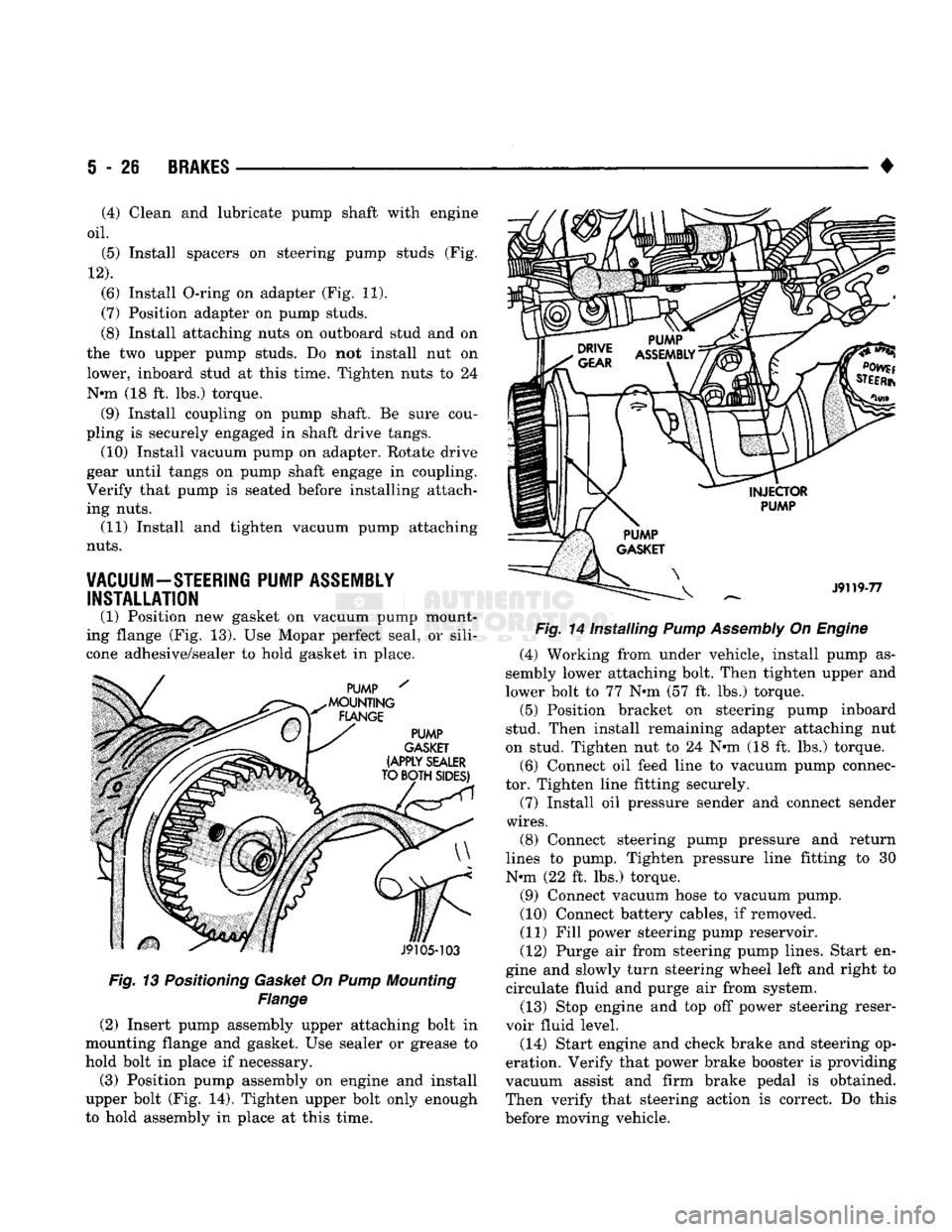
(3) Position pump assembly on engine and install
upper bolt (Fig. 14). Tighten upper bolt only enough
to hold assembly in place at this time. •
Fig. 14 Installing Pump Assembly On Engine (4) Working from under vehicle, install pump as
sembly lower attaching bolt. Then tighten upper and
lower bolt to 77 N»m (57 ft. lbs.) torque. (5) Position bracket on steering pump inboard
stud. Then install remaining adapter attaching nut
on stud. Tighten nut to 24 N«m (18 ft. lbs.) torque.
(6) Connect oil feed line to vacuum pump connec
tor. Tighten line fitting securely.
(7) Install oil pressure sender and connect sender
wires.
(8) Connect steering pump pressure and return
lines to pump. Tighten pressure line fitting to 30
N-m (22 ft. lbs.) torque.
(9) Connect vacuum hose to vacuum pump.
(10) Connect battery cables, if removed.
(11) Fill power steering pump reservoir.
(12) Purge air from steering pump lines. Start en
gine and slowly turn steering wheel left and right to circulate fluid and purge air from system.
(13) Stop engine and top off power steering reser
voir fluid level.
(14) Start engine and check brake and steering op
eration. Verify that power brake booster is providing
vacuum assist and firm brake pedal is obtained.
Then verify that steering action is correct. Do this
before moving vehicle.
(4) Clean and lubricate pump shaft with engine
oil.
(5) Install spacers on steering pump studs (Fig.
12).
(6) Install O-ring on adapter (Fig. 11).
(7) Position adapter on pump studs.
(8) Install attaching nuts on outboard stud and on
the two upper pump studs. Do not install nut on
lower, inboard stud at this time. Tighten nuts to 24
N-m (18 ft. lbs.) torque. (9) Install coupling on pump shaft. Be sure cou
pling is securely engaged in shaft drive tangs. (10) Install vacuum pump on adapter. Rotate drive
gear until tangs on pump shaft engage in coupling.
Verify that pump is seated before installing attach
ing nuts. (11) Install and tighten vacuum pump attaching
nuts.
VACUUM-STEERING PUMP ASSEMBLY INSTALLATION
(1) Position new gasket on vacuum pump mount
ing flange (Fig. 13). Use Mopar perfect seal, or sili
cone adhesive/sealer to hold gasket in place.
Page 214 of 1502
•
BRAKES
5 - 27 CHRYSLER
DISC
BRAKE
INDEX
page
Caliper
Installation
. 33
Caliper Overhaul
32
Caliper Removal
31
Disc
Brake Inspection
29
Disc
Brakeshoe
Installation
, 31
GENERAL
INFORMATION
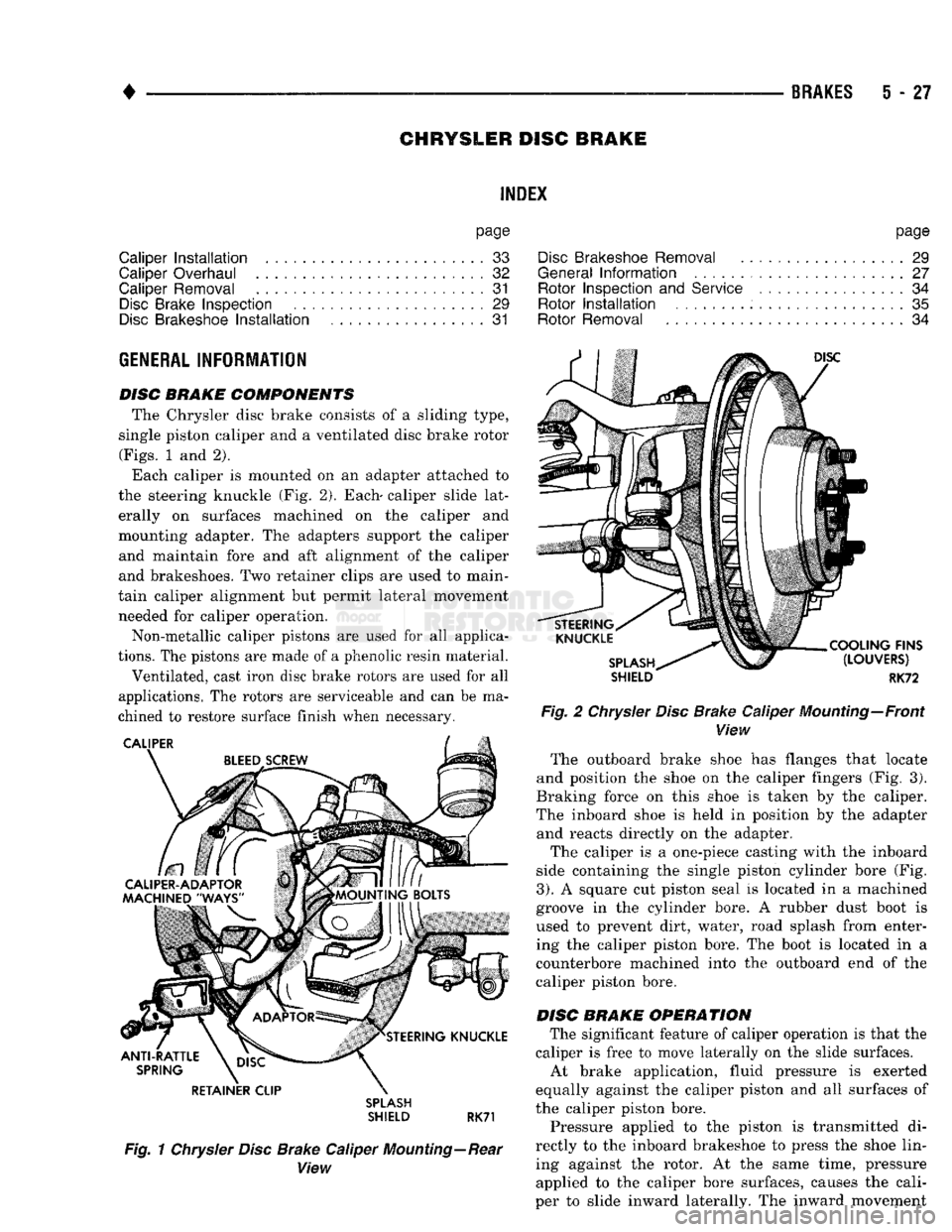
DISC BRAKE COMPONENTS The Chrysler disc brake consists of a sliding type,
single piston caliper and a ventilated disc brake rotor
(Figs.
1 and 2).
Each caliper is mounted on an adapter attached to
the steering knuckle (Fig. 2). Each- caliper slide lat erally on surfaces machined on the caliper and
mounting adapter. The adapters support the caliper and maintain fore and aft alignment of the caliper
and brakeshoes. Two retainer clips are used to main
tain caliper alignment but permit lateral movement needed for caliper operation.
Non-metallic caliper pistons are used for all applica
tions.
The pistons are made of a phenolic resin material.
Ventilated, cast iron disc brake rotors are used for all
applications. The rotors are serviceable and can be ma
chined to restore surface finish when necessary. RETAINER CLIP
SPLASH
SHIELD RK71
Fig. 1 Chrysler Disc Brake Caliper Mounting—Rear View
page
Disc
Brakeshoe Removal
29
General
Information
....................... 27
Rotor Inspection
and
Service
................ 34
Rotor
Installation
. 35
Rotor Removal
34
SHIELD
RK72
Fig. 2 Chrysler Disc Brake Caliper Mounting—Front View The outboard brake shoe has flanges that locate
and position the shoe on the caliper fingers (Fig. 3).
Braking force on this shoe is taken by the caliper.
The inboard shoe is held in position by the adapter and reacts directly on the adapter.
The caliper is a one-piece casting with the inboard
side containing the single piston cylinder bore (Fig.
3).
A square cut piston seal is located in a machined
groove in the cylinder bore. A rubber dust boot is used to prevent dirt, water, road splash from enter
ing the caliper piston bore. The boot is located in a
counterbore machined into the outboard end of the
caliper piston bore.
DISC BRAKE OPERATION The significant feature of caliper operation is that the
caliper is free to move laterally on the slide surfaces. At brake application, fluid pressure is exerted
equally against the caliper piston and all surfaces of
the caliper piston bore.
Pressure applied to the piston is transmitted di
rectly to the inboard brakeshoe to press the shoe lin ing against the rotor. At the same time, pressure applied to the caliper bore surfaces, causes the cali
per to slide inward laterally. The inward movement
Page 216 of 1502
•
BRAKES
5 - 29 presses the outboard shoe lining against the opposite
side of the rotor to complete braking action.
The application or release of fluid pressure causes
only a very slight movement of the caliper and pis
ton. At brake release, the piston and caliper return
to the non-applied position.
The brakeshoes do not retract an appreciable dis
tance from the rotor. The minimal running clearance
between the lining and rotor provides improved re sponse and reduced pedal travel. It also helps in pre
venting dirt and foreign material from lodging
between the shoe and rotor surfaces.
DISC
BRAKE
LINING WEAR COMPENSATION
Normal lining wear is compensated for by extension
of the caliper piston and by lateral movement of the cal
iper in the adapter. Piston position is also determined
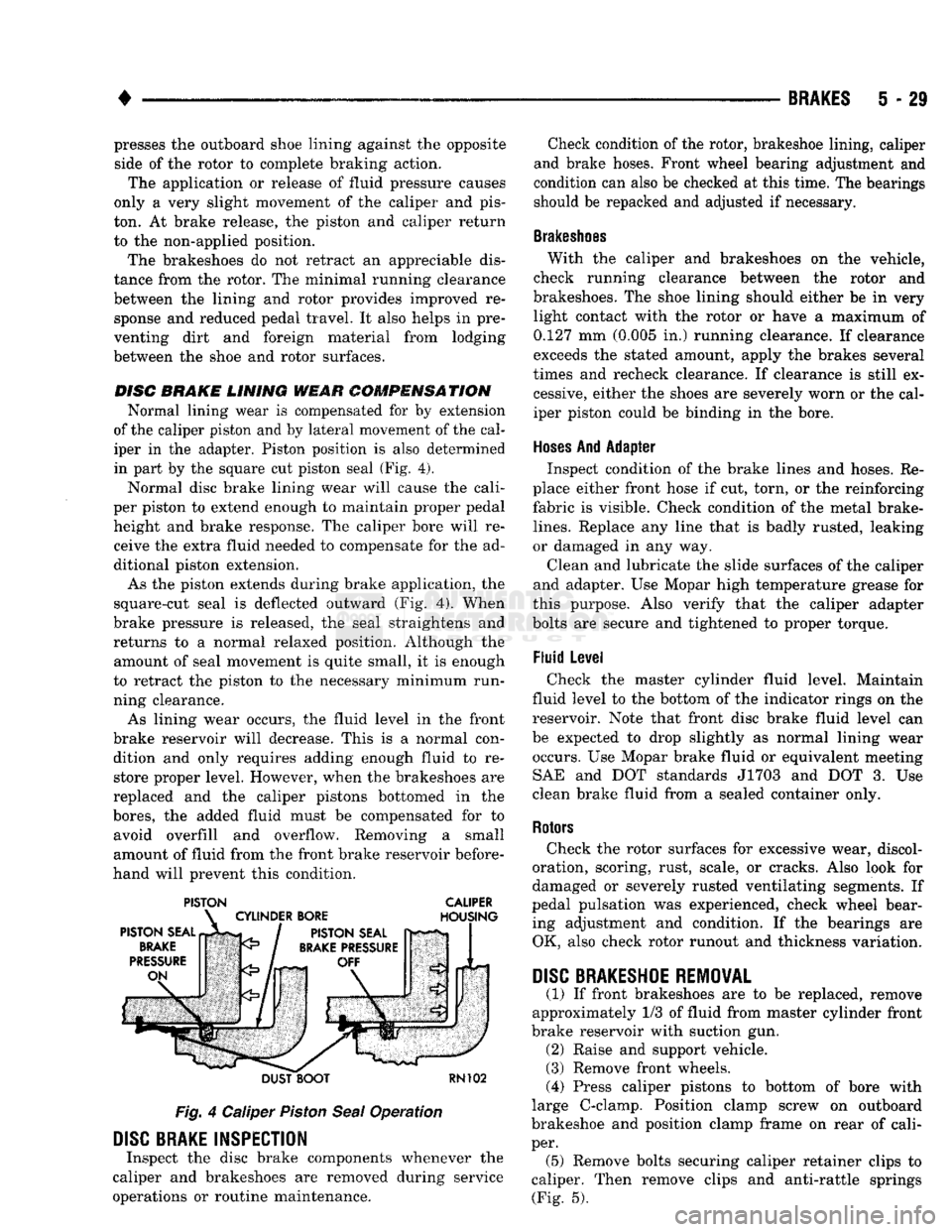
in part by the square cut piston seal (Fig. 4).
Normal disc brake lining wear will cause the cali
per piston to extend enough to maintain proper pedal height and brake response. The caliper bore will receive the extra fluid needed to compensate for the ad
ditional piston extension.
As the piston extends during brake application, the
square-cut seal is deflected outward (Fig. 4). When
brake pressure is released, the seal straightens and
returns to a normal relaxed position. Although the amount of seal movement is quite small, it is enough
to retract the piston to the necessary minimum run
ning clearance.
As lining wear occurs, the fluid level in the front
brake reservoir will decrease. This is a normal con dition and only requires adding enough fluid to restore proper level. However, when the brakeshoes are
replaced and the caliper pistons bottomed in the
bores,
the added fluid must be compensated for to avoid overfill and overflow. Removing a small
amount of fluid from the front brake reservoir before
hand will prevent this condition.
PISTON CALIPER
DUST BOOT
RN102
Fig.
4 Caliper
Piston
Seal
Operation
DISC
BRAKE INSPECTION
Inspect the disc brake components whenever the
caliper and brakeshoes are removed during service
operations or routine maintenance. Check condition of the rotor, brakeshoe lining, caliper
and brake hoses. Front wheel bearing adjustment and
condition can also be checked at this time. The bearings
should be repacked and adjusted if necessary.
Brakeshoes
With the caliper and brakeshoes on the vehicle,
check running clearance between the rotor and
brakeshoes. The shoe lining should either be in very light contact with the rotor or have a maximum of
0.127 mm (0.005 in.) running clearance. If clearance
exceeds the stated amount, apply the brakes several
times and recheck clearance. If clearance is still ex cessive, either the shoes are severely worn or the cal
iper piston could be binding in the bore.
Hoses
And Adapter Inspect condition of the brake lines and hoses. Re
place either front hose if cut, torn, or the reinforcing
fabric is visible. Check condition of the metal brake-
lines.
Replace any line that is badly rusted, leaking
or damaged in any way.
Clean and lubricate the slide surfaces of the caliper
and adapter. Use Mopar high temperature grease for
this purpose. Also verify that the caliper adapter
bolts are secure and tightened to proper torque.
Fluid Level Check the master cylinder fluid level. Maintain
fluid level to the bottom of the indicator rings on the
reservoir. Note that front disc brake fluid level can
be expected to drop slightly as normal lining wear occurs. Use Mopar brake fluid or equivalent meeting SAE and DOT standards J1703 and DOT 3. Use
clean brake fluid from a sealed container only.
Rotors
Check the rotor surfaces for excessive wear, discol
oration, scoring, rust, scale, or cracks. Also look for
damaged or severely rusted ventilating segments. If
pedal pulsation was experienced, check wheel bear ing adjustment and condition. If the bearings are OK, also check rotor runout and thickness variation.
DISC
BRAKESHOE
REMOVAL
(1) If front brakeshoes are to be replaced, remove
approximately 1/3 of fluid from master cylinder front
brake reservoir with suction gun. (2) Raise and support vehicle.
(3) Remove front wheels.
(4) Press caliper pistons to bottom of bore with
large C-clamp. Position clamp screw on outboard
brakeshoe and position clamp frame on rear of cali
per. (5) Remove bolts securing caliper retainer clips to
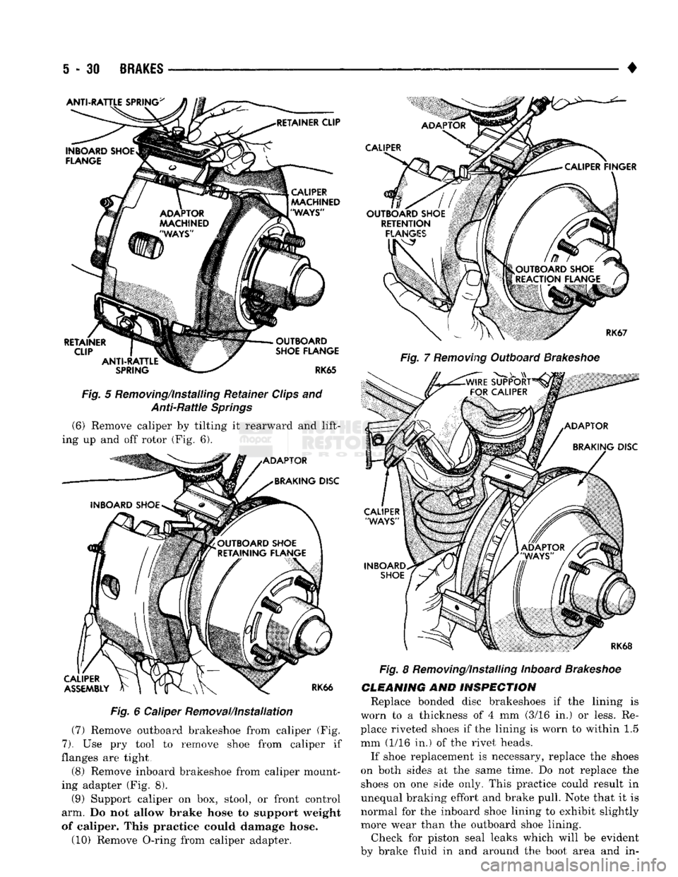
caliper. Then remove clips and anti-rattle springs (Fig. 5).
Page 217 of 1502
5 - 31
BRAKES
Fig.
5 Removing/installing Retainer Clips and Anti-Rattle Springs (6) Remove caliper by tilting it rearward and lift
ing up and off rotor (Fig. 6).
Fig.
6 Caliper Removal/Installation
(7) Remove outboard brakeshoe from caliper (Fig.
7).
Use pry tool to remove shoe from caliper if
flanges are tight,
(8) Remove inboard brakeshoe from caliper mount
ing adapter (Fig. 8). (9) Support caliper on box, stool, or front control
arm. Do not allow brake hose to support weight
of caliper. This practice could damage hose.
(10) Remove O-ring from caliper adapter. •
Fig.
7
Removing
Outboard
Brakeshoe
Fig.
8 Removing/Installing Inboard
Brakeshoe
CLEANING
AND
INSPECTION
Replace bonded disc brakeshoes if the lining is
worn to a thickness of 4 mm (3/16 in.) or less. Re
place riveted shoes if the lining is worn to within 1.5
mm (1/16 in.) of the rivet heads.
If shoe replacement is necessary, replace the shoes
on both sides at the same time. Do not replace the shoes on one side only. This practice could result in
unequal braking effort and brake pull. Note that it is
normal for the inboard shoe lining to exhibit slightly more wear than the outboard shoe lining. Check for piston seal leaks which will be evident
by brake fluid in and around the boot area and in-