ECO mode DODGE TRUCK 1993 Service Owner's Guide
[x] Cancel search | Manufacturer: DODGE, Model Year: 1993, Model line: TRUCK, Model: DODGE TRUCK 1993Pages: 1502, PDF Size: 80.97 MB
Page 275 of 1502
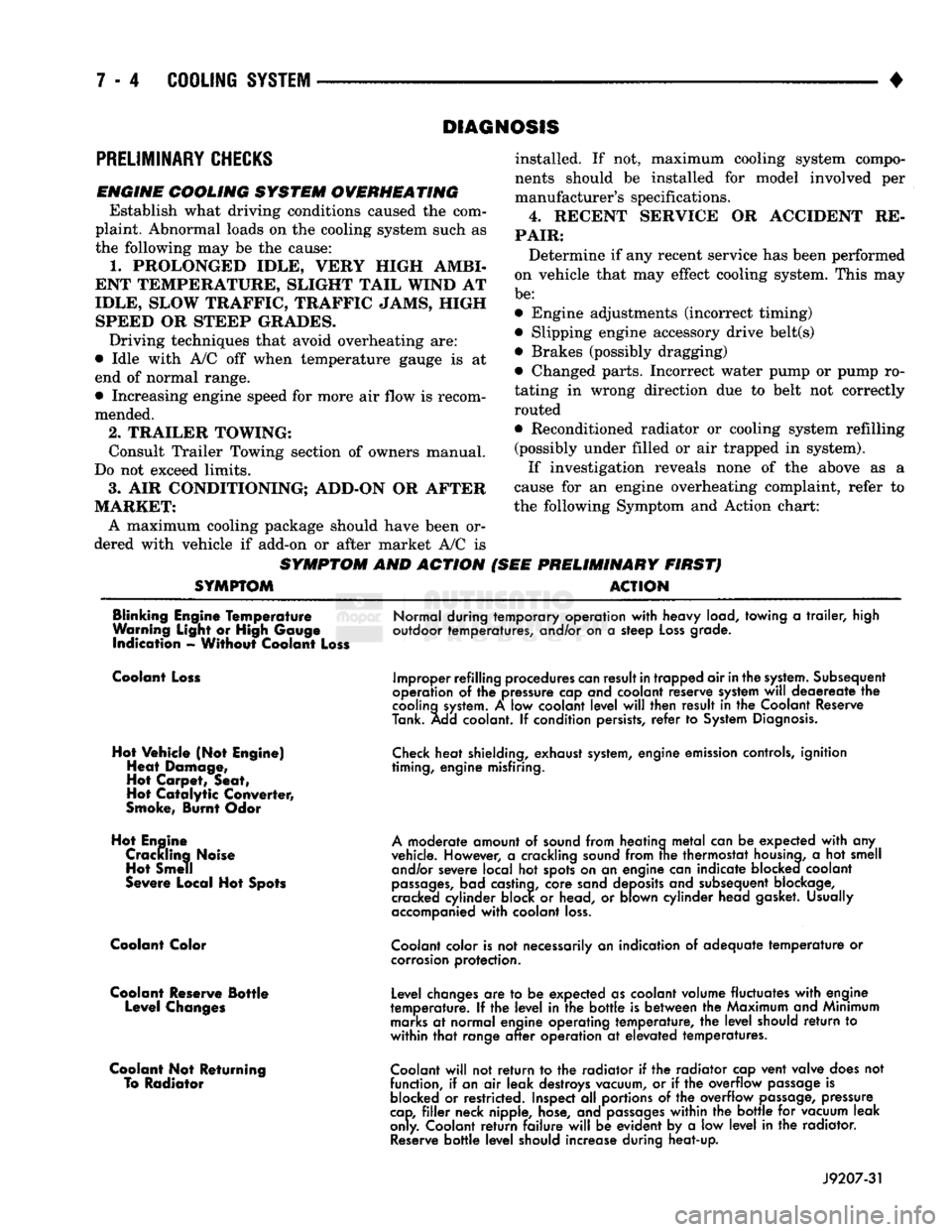
DIAGNOSIS
PRELIMINARY
CHECKS
ENGINE COOLING SYSTEM OVERHEATING Establish what driving conditions caused the com
plaint. Abnormal loads on the cooling system such as
the following may be the cause:
1.
PROLONGED IDLE, VERY HIGH AMBI
ENT TEMPERATURE, SLIGHT TAIL WIND AT
IDLE, SLOW TRAFFIC, TRAFFIC JAMS, HIGH SPEED OR STEEP GRADES.
Driving techniques that avoid overheating are:
• Idle with A/C off when temperature gauge is at
end of normal range. * Increasing engine speed for more air flow is recom
mended.
2.
TRAILER TOWING: Consult Trailer Towing section of owners manual.
Do not exceed limits.
3.
AIR CONDITIONING; ADD-ON OR AFTER
MARKET: A maximum cooling package should have been or
dered with vehicle if add-on or after market A/C is
SYMPTOM AND ACTION
SYMPTOM
installed. If not, maximum cooling system compo
nents should be installed for model involved per
manufacturer's specifications.
4.
RECENT SERVICE OR ACCIDENT RE
PAIR:
Determine if any recent service has been performed
on vehicle that may effect cooling system. This may
be:
• Engine adjustments (incorrect timing)
• Slipping engine accessory drive belt(s) • Brakes (possibly dragging)
• Changed parts. Incorrect water pump or pump ro
tating in wrong direction due to belt not correctly
routed
• Reconditioned radiator or cooling system refilling (possibly under filled or air trapped in system).
If investigation reveals none of the above as a
cause for an engine overheating complaint, refer to
the following Symptom and Action chart:
PRELIMINARY FIRST) ACTION
Blinking Engine Temperature
Warning Light or High Gauge indication - Without Coolant Loss
Normal during temporary operation
with
heavy load, towing
a
trailer,
high
outdoor temperatures, and/or on
a
steep
Loss
grade.
Coolant Loss
Hot Vehicle (Not Engine) Heat Damage,
Hot Carpet, Seat,
Hot
Catalytic
Converter,
Smoke, Burnt Odor
Hot Engine Crackling Noise Hot Smell
Severe Local Hot Spots
Coolant Color
Coolant Reserve Bottle Level Changes
Coolant Not Returning To Radiator
Improper refilling procedures
can
result
in
trapped air
in
the
system.
Subsequent
operation
of the
pressure cap and coolant reserve system
will
deaereate
the
cooling
system.
A low
coolant
level
will
then result
in the
Coolant Reserve
Tank. Add coolant.
If
condition persists,
refer
to
System
Diagnosis.
Check
heat shielding, exhaust
system,
engine emission controls, ignition
timing, engine misfiring.
A
moderate amount
of
sound from heating
metal
can
be
expected
with
any
vehicle. However,
a
crackling sound from
trie
thermostat
housing,
a hot
smell and/or severe local
hot
spots on
an
engine can indicate blocked coolant
passages,
bad castina, core sand deposits and subsequent blockage,
cracked cylinder block
or
head,
or
blown cylinder head gasket. Usually
accompanied
with
coolant
loss.
Coolant
color is
not
necessarily
an
indication
of
adequate
temperature
or
corrosion
protection.
Level changes
are to be
expected as coolant volume fluctuates
with
engine
temperature.
If the
level
in the
bottle
is
between
the
Maximum and Minimum
marks
at
normal engine operating temperature,
the
level
should
return
to
within
that
range
after
operation
at
elevated temperatures.
Coolant
will
not
return
to the
radiator
if the
radiator cap vent valve does
not
function,
if
an
air
leak destroys vacuum,
or if the
overflow
passage
is
blocked
or
restricted. Inspect
all
portions
of the
overflow
passage,
pressure
cap,
filler
neck nipple, hose, and
passages
within
the
bottle
for
vacuum leak
only. Coolant
return
failure
will
be
evident
by a low
level
in the
radiator.
Reserve
bottle
level
should increase during heat-up.
J9207-31
Page 305 of 1502
7 - 34
COOLING SYSTEM
•
WARNING;
DO NOT
REMOVE
THE
CYLINDER
BLOCK DRAIN PLUGS
OR
LOOSEN
THE
RADIATOR
DRAINCOCK
WITH
THE
SYSTEM
HOT AND
UNDER
PRESSURE.
SERIOUS BURNS FROM COOLANT
CAN OCCUR.
(2) Drain the cooling system. Refer to Draining
Cooling System in this group. (3) Remove hose clamps and hoses from radiator.
Remove coolant reserve/overflow tank hose from ra diator filler neck nipple.
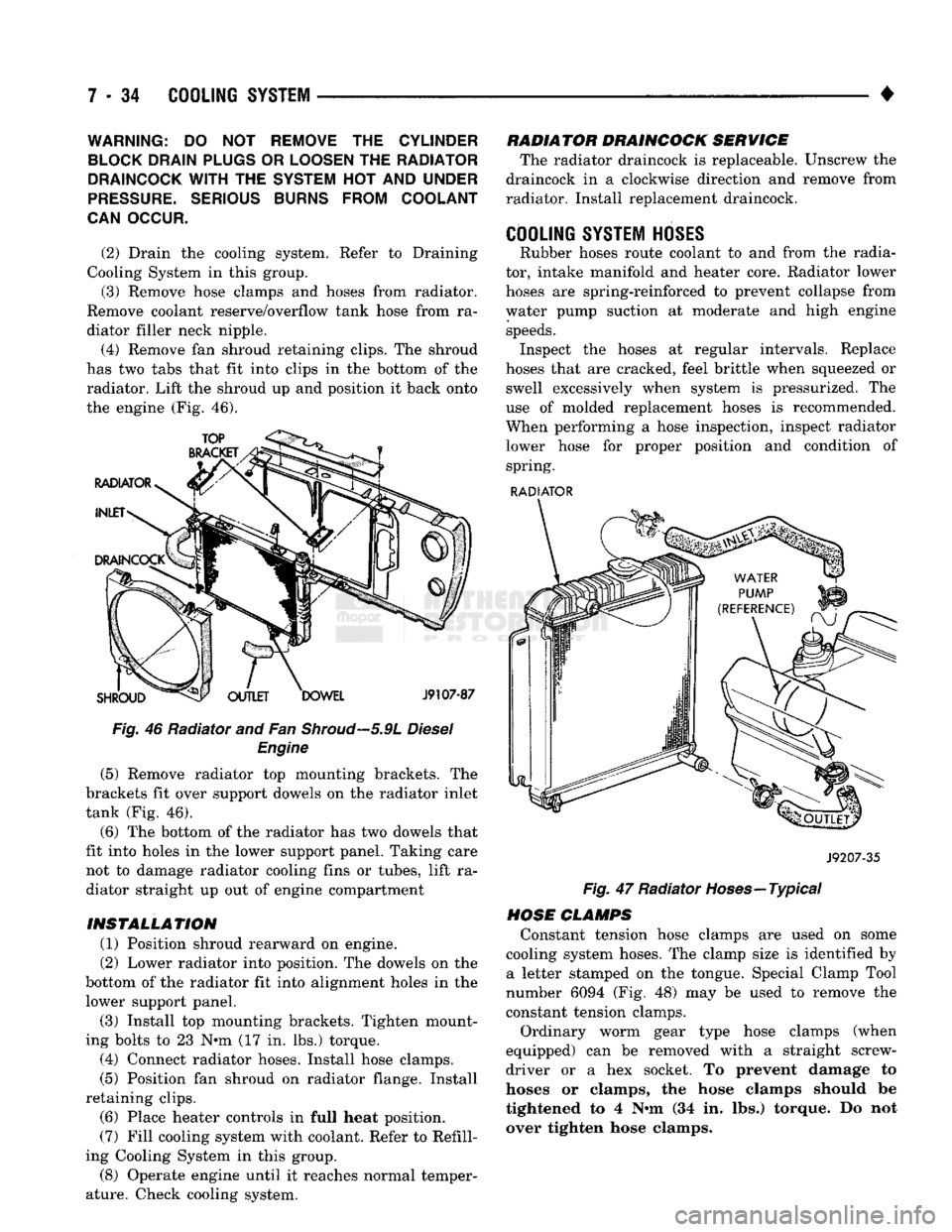
(4) Remove fan shroud retaining clips. The shroud
has two tabs that fit into clips in the bottom of the radiator. Lift the shroud up and position it back onto
the engine (Fig. 46).
Fig. 46 Radiator and Fan
Shroud—5.9L
Diesel Engine
(5) Remove radiator top mounting brackets. The
brackets fit over support dowels on the radiator inlet
tank (Fig. 46).
(6) The bottom of the radiator has two dowels that
fit into holes in the lower support panel. Taking care not to damage radiator cooling fins or tubes, lift ra
diator straight up out of engine compartment
INSTALLATION (1) Position shroud rearward on engine.
(2) Lower radiator into position. The dowels on the
bottom of the radiator fit into alignment holes in the lower support panel.
(3) Install top mounting brackets. Tighten mount
ing bolts to 23 N*m (17 in. lbs.) torque. (4) Connect radiator hoses. Install hose clamps.
(5) Position fan shroud on radiator flange. Install
retaining clips. (6) Place heater controls in full heat position.
(7) Fill cooling system with coolant. Refer to Refill
ing Cooling System in this group.
(8) Operate engine until it reaches normal temper
ature. Check cooling system. RADIATOR DRAINCOCK SERVICE
The radiator draincock is replaceable. Unscrew the
draincock in a clockwise direction and remove from
radiator. Install replacement draincock.
COOLING SYSTEM HOSES
Rubber hoses route coolant to and from the radia
tor, intake manifold and heater core. Radiator lower
hoses are spring-reinforced to prevent collapse from
water pump suction at moderate and high engine speeds. Inspect the hoses at regular intervals. Replace
hoses that are cracked, feel brittle when squeezed or swell excessively when system is pressurized. The
use of molded replacement hoses is recommended.
When performing a hose inspection, inspect radiator lower hose for proper position and condition of spring.
RADIATOR
J9207-35
Fig. 47 Radiator Hoses—Typical
HOSE CLAMPS Constant tension hose clamps are used on some
cooling system hoses. The clamp size is identified by a letter stamped on the tongue. Special Clamp Tool
number 6094 (Fig. 48) may be used to remove the
constant tension clamps.
Ordinary worm gear type hose clamps (when
equipped) can be removed with a straight screw
driver or a hex socket. To prevent damage to
hoses or clamps, the hose clamps should be
tightened to 4 N«m (34 in. lbs.) torque. Do not
over tighten hose clamps.
Page 319 of 1502
7
- 48
COOLING
SYSTEM
•
ENGINE BLOCK HEATERS
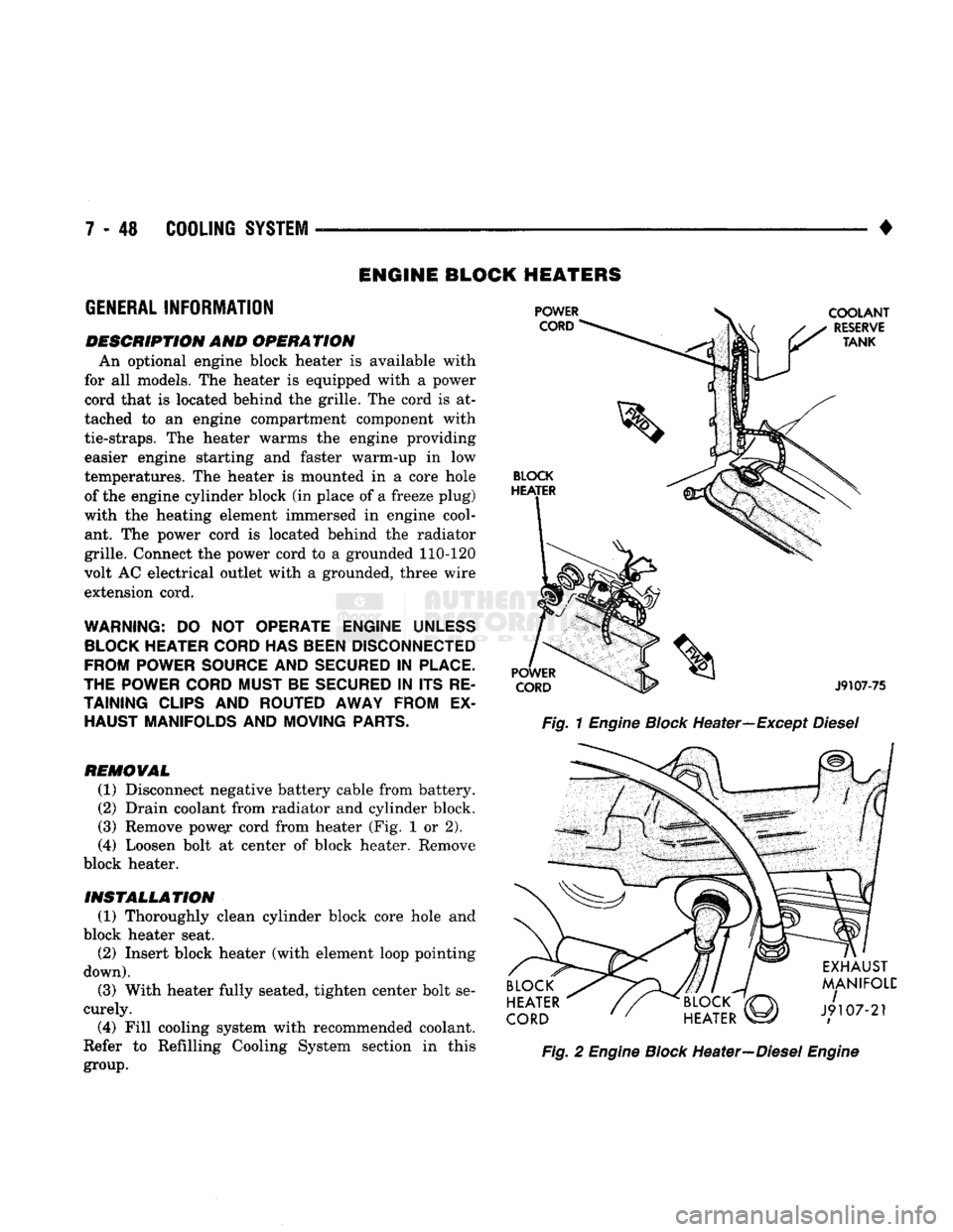
GENERAL
INFORMATION
DESCRIPTION AND OPERATION An optional engine block heater
is
available with
for
all
models. The heater
is
equipped with
a
power
cord that
is
located behind the grille. The cord
is at
tached
to an
engine compartment component with
tie-straps.
The
heater warms
the
engine providing easier engine starting
and
faster warm-up
in low
temperatures. The heater
is
mounted
in a
core hole of the engine cylinder block (in place of
a
freeze plug)
with
the
heating element immersed
in
engine cool ant.
The
power cord
is
located behind
the
radiator
grille. Connect the power cord
to a
grounded 110-120
volt AC electrical outlet with
a
grounded, three wire
extension cord.
WARNING:
DO NOT
OPERATE ENGINE
UNLESS
BLOCK
HEATER
CORD
HAS
BEEN
DISCONNECTED
FROM POWER
SOURCE
AND
SECURED
IN
PLACE.
THE POWER
CORD
MUST BE
SECURED
IN ITS RE
TAINING
CLIPS
AND ROUTED AWAY FROM
EX
HAUST MANIFOLDS AND MOVING
PARTS.
REMOVAL
(1) Disconnect negative battery cable from battery.
(2) Drain coolant from radiator and cylinder block.
(3) Remove pow^r cord from heater (Fig.
1 or 2).
(4)
Loosen bolt
at
center
of
block heater. Remove
block heater.
INSTALLATION (1) Thoroughly clean cylinder block core hole
and
block heater seat. (2) Insert block heater (with element loop pointing
down).
(3) With heater fully seated, tighten center bolt se
curely.
(4)
Fill cooling system with recommended coolant.
Refer
to
Refilling Cooling System section
in
this
group.
Fig.
1
Engine
Block
Heater—Except
Diesel
Fig.
2
Engine
Block
Heater—Diesel
Engine
Page 352 of 1502
•
IGNITION
SYSTEMS
8D
- 1
CONTENTS
page page
COMPONENT IDENTIFICATION/SYSTEM DIAGNOSTICS/SERVICE PROCEDURES
7
OPERATION
1
IGNITION SWITCH
25
COMPONENT REMOVAL/INSTALLATION
..... 18
SPECIFICATIONS
28
COMPONENT
IDENTIFICATION/SYSTEM OPERATION
INDEX
page
Automatic
Shut Down (ASD) Relay
1
Camshaft Position Sensor
2
Crankshaft Position Sensor
2
Distributors
3
Engine Coolant
Temperature
Sensor
...........
4
General
Information
1
page
Ignition
Coil
3
Intake
Manifold Charge
Air
Temperature
Sensor
. . 4
Manifold Absolute Pressure (MAP) Sensor
4
Powertrain
Control
Module (PCM)
. 5
Throttle
Position Sensor
5
GENERAL
INFORMATION
Throughout this group, references
are
made
to
par
ticular vehicle models
by
alphabetical designation
or
by
the
particular vehicle nameplate.
A
chart showing a breakdown
of
alphabetical designations
is
included
in
the
Introduction group
at the
beginning
of
this
manual. 5.9L
gas
powered engines will
be
referred
to as ei
ther: LDC (Light Duty Cycle),
or
HDC (Heavy Duty Cycle). This section
of the
group, Component Identifica
tion/System Operation, will discuss ignition system operation
and
will identify ignition system compo
nents.
For diagnostic procedures
and
adjustments, refer
to
the Diagnostics/Service Procedures section
of
this
group.
For removal
and
installation
of
ignition system
components, refer
to the
Component Removal/Instal
lation section
of
this group. For other useful information, refer
to
On-Board
Di
agnostics
in the
General Diagnosis sections
of
Group
14,
Fuel System
in
this manual. For operation
of the DRB II
Diagnostic Scan Tool,
refer
to the
appropriate Powertrain Diagnostic Proce
dures service manual.
An Ignition specifications section
is
included
at the
end
of
this group.
A
general Maintenance Schedule (mileage intervals)
for
ignition related items
can be
found
in
Group
0,
Lubrication and Maintenance. This
schedule
can
also
be
found
in the
Owners Manual.
IGNITION
SYSTEMS
The ignition systems used
on all
engines
are
basi
cally identical. Similarities
and
differences between
the systems will
be
discussed.
A sequential multi-port fuel injection system
is
used
on all gas
powered engines.
The ignition system
is
controlled
by the
powertrain
control module (PCM)
on all
engines.
The
PCM
was
formerly referred
to as the
SBEC
or
engine control ler.
The ignition system consists
of:
• Spark Plugs
• Ignition Coil
• Secondary Ignition Cables
• Ignition distributor. Contains rotor
and
camshaft
position sensor • Powertrain Control Module (PCM)
• Crankshaft Position Sensor
AUTOMATIC SHUT DOWN (ASD) RELAY
The automatic shut down (ASD) relay
is
located
in
the engine compartment (Fig.
1). As one of its
func
tions,
the ASD
relay will supply battery voltage
to
the ignition coil.
The
ground circuit
for the
ASD
re
lay
is
controlled
by the
powertrain control module (PCM).
The PCM
regulates
ASD
relay operation
by
switching
the
ground circuit on-and-off.
IGNITION
SYSTEMS
Page 432 of 1502

•
WINDSHIELD WIPER
AND
WASHER SYSTEMS
8K - 1
WINDSHIELD WIPER
AND
WASHER SYSTEMS
CONTENTS
page
INTERMITTENT WINDSHIELD WIPER FUNCTION AND SWITCH TESTING PROCEDURES
6
TWO SPEED WINDSHIELD WIPER MOTOR
AND
SWITCH TESTING PROCEDURES
1
GENERAL
INFORMATION
The windshield wipers
can be
operated with
the
windshield wiper switch only when
the
ignition switch
is in the
ACCESSORY
or RUN
position.
A
fuse located
in the
fuse block protects
the
circuitry
of
the wiper system
and the
vehicle. The same motor
is
used
for
standard
and
intermit
tent wipe systems. The wiper motor
has
permanent magnet fields.
The
speeds
are
determined
by
current flow
to the
appro
priate
set of
brushes. The intermittent wipe system
in
addition
to low
page
WINDSHIELD WASHERS .. 10
WINDSHIELD WIPER SYSTEM SERVICE PROCEDURES 7
and high speed,
has a
delay mode.
The
delay mode
has
a
range
of 2 to 15
seconds. This
is
accomplished
by
a
variable resistor
in the
wiper switch
and is
con trolled electrically
by a
control module.
The wiper system completes
the
wipe cycle when
the switch
is
turned
OFF. The
blades park
in the
lowest portion
of the
wipe pattern.
Depressing
the
washer knob while
the
system
is in
the
OFF
position, • turns
the
wiper motor
on
• allows
the
motor
to
operate through
3-4
wipe
cy
cles
and
then turn
OFF.
TWO SPEED WINDSHIELD WIPER MOTOR
AND
SWITCH TESTING PROCEDURES INDEX
page
Multifunction
(Two
Speed
Wiper) Switch Testing
Procedures
4
TWO SPEED WIPER MOTOR TESTING PROCEDURES
The following
is a
list
of
general wiper motor sys
tem problems.
It
contains
the
tests that
are to be
per
formed
to
locate
the
faulty part,
and the
corrective action
to be
taken.
The
same motor
is
used
for
stan
dard
and
optional systems.
If the
malfunction
in
volves only
the
Delay mode, switch,
or
wiring, refer
to
the
Intermittent Windshield Wiper Motor
and
Switch Service Procedures.
CONDITION
Motor will
not run in any
switch position.
PROCEDURE
(1) Check
for a
blown fuse
in the
fuse block.
(a)
If
fuse
is
good, proceed
to
step
No. 2.
(b)
If
fuse
is
defective, replace
and
check motor
operation
in all
switch positions.
(c)
If
motor
is
still inoperative
and the
fuse does
not blow, proceed
to
step
No. 2.
page
Two Speed
Wiper Motor Testing Procedures
1
(d)
If
replacement fuse blows, proceed
to
step
No.
5.
(2) Place switch
in low
speed position.
(3) Listen
to
motor.
If you
cannot hear
it
running,
proceed
to
step
No. 4. If you
hear
it
running, check
motor output shaft.
If
output shaft
is not
turning,
re
place motor assembly.
If it is
turning, crank
arm or
drive link
is not
properly connected. Replace worn
parts and/or properly connect drive link
to the
motor output shaft.
(4) Connect
a
voltmeter between motor terminal
"L"
and
ground strap
(Fig. 1). If
there
is no
voltage
or very little voltage (less than
one
volt) present,
move negative test lead from
the
ground strap
to
bat
tery negative terminal.
(a)
If an
increase
in
voltage
is
noticed,
the
prob
lem
is a bad
ground circuit. Make sure
the
motor
mounting
is
free
of
paint
and
that nuts
or
bolts
are
tight.
Page 437 of 1502

8K
- 6
WINDSHIELD WIPER
AND
WASHER SYSTEMS
• INTERMITTENT WINDSHIELD WIPER FUNCTION
AND
SWITCH TESTING
PROCEDURES
INTERMITTENT
WIPER
FUNCTION
TESTING
PROCEDURES
The intermittent wipe and standard two speed mo
tors are identical. Refer to previous sections for diag
nosis of system problems which do not involve the
DELAY function. If problem occurs only in the DE LAY mode, the following tests are to be performed.
These tests involve disconnecting the intermittent wipe control unit which can be found on the steering column support bracket (Fig. 2).
CONDITION Excessive delay (more than 30 seconds) or in
adequate variation in delay.
PROCEDURE Variations in delay should be as follows: (1) Minimum delay (delay control to extreme coun
terclockwise position before first detent) 1/2 to 2 sec
onds.
(2) Maximum delay (delay control to extreme
clockwise position before off detent) 10 to 30 seconds.
(3) If there is excessive delay or no variations in
delay proceed to intermittent wipe switch test.
CONDITION In DELAY mode wipers run continually when
wash is operated but do not provide an extra
wipe when the wash control is released.
PROCEDURE Replace the control unit.
CONDITION ' Wipers start erratically during DELAY mode.
PROCEDURE (1) Verify that the ground connection at the in
strument panel is making good connection (free from
paint) and is tight.
(2) Verify that the motor ground strap is making
good contact and that the motor mounting bolts are
tight.
(3) Verify that the wiring ground connections for
the intermittent wipe control unit and the wiper switch are tight.
(4) If condition is not corrected, replace control
unit.
MULTIFUNCTION (INTERMITTENT WIPER) SWITCH
TESTING
PROCEDURES
Refer to Multifunction (Two Speed Wiper) Switch
Testing Procedures using the following continuity chart.
i
24 23 22
21 20 19
17 16 15 14
/V~\M3
12 11 10 9 8
7
6 V5^4 3
.
2 1
EZJ
CZ3 CZ3 C3 Jr
L
JT
MULTIFUNCTION
SWITCH
PINS
SWITCH
POSITION
CONTINUITY
BETWEEN
OFF
PIN
6 AND PIN 7
DELAY
PIN 8 AND PIN 9
PIN 2 AND PIN 4
PIN
1
AND PIN 2
PIN
1
AND PIN 4
LOW PIN 4 AND PIN 6
HIGH
PIN 4 AND PIN 5
WASH
PIN 3 AND PIN 4
*
RESISTANCE
AT
AAAXIMUM
DELAY
POSITION
SHOULD
BE
BETWEEN
270,000
OHMS
AND
330,000
OHMS.
•RESISTANCE
AT
MINIMUM
DELAY
POSITION
SHOULD
BE
ZERO
WITH
OHMMETER
SET ON
HIGH
OHM
SCALE.
918J-4
Fig.
11ntermittent
Wipe
Switch
Continuity Chart
INTERMITTENT WIPE MODULE LOCATION
The intermittent wipe module is located to the
right of the steering column on the back side of the instrument panel (Fig. 2).
BUZZER
MODULE
INTERMITTENT
WIPE
MODULE
Fig.
2
Intermittent
Wipe
Module
Location
Page 477 of 1502
8W
- 2
WIRING
DIAGRAMS
•
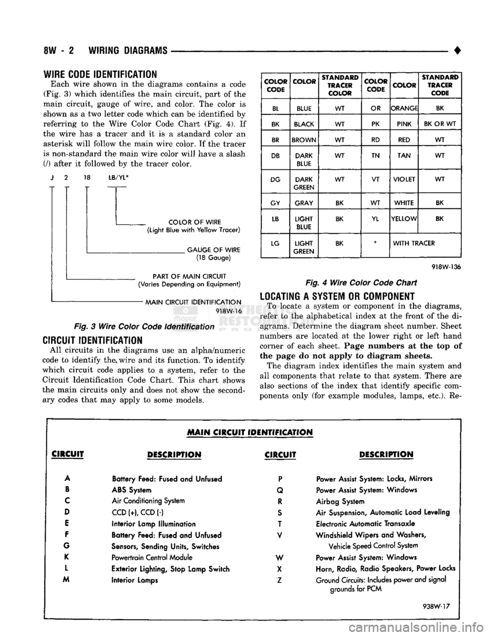
WIRE CODE
IDENTIFICATION
Each wire shown in the diagrams contains a code
(Fig. 3) which identifies the main circuit, part of the
main circuit, gauge of wire, and color. The color is shown as a two letter code which can be identified by
referring to the Wire Color Code Chart (Fig. 4). If
the wire has a tracer and it is a standard color an asterisk will follow the main wire color. If the tracer
is non-standard the main wire color will have a slash (/) after it followed by the tracer color. 18
LB/YL*
COLOR
OF
WIRE
(Light
Blue
with
Yellow
Tracer)
.
GAUGE
OF
WIRE
(18
Gauge)
PART
OF
AAAIN CIRCUIT
(Varies
Depending
on
Equipment)
AAAIN CIRCUIT
IDENTIFICATION
918W-16
Fig.
3
Wire
Color
Code
Identification
CIRCUIT IDENTIFICATION
All circuits in the diagrams use an alpha/numeric
code to identify the, wire and its function. To identify
which circuit code applies to a system, refer to the
Circuit Identification Code Chart. This chart shows
the main circuits only and does not show the second ary codes that may apply to some models.
COLOR
CODE COLOR
STANDARD
TRACER
COLOR COLOR
CODE
COLOR
STANDARD
TRACER
CODE
BL BLUE WT
OR ORANGE
BK
BK
BLACK
WT PK
PINK
BK
OR WT
BR
BROWN
WT RD
RED WT
DB DARK
BLUE WT
TN
TAN WT
DG DARK
GREEN WT
VT
VIOLET
WT
GY GRAY
BK
WT
WHITE
BK
LB
LIGHT
BLUE
BK
YL YELLOW
BK
LG
LIGHT
GREEN
BK
*
WITH
TRACER
918W-136
Fig.
4
Wire
Color
Code
Chart
LOCATING
A
SYSTEM
OR
COMPONENT
To locate a system or component in the diagrams,
refer to the alphabetical index at the front of the di agrams. Determine the diagram sheet number. Sheet
numbers are located at the lower right or left hand
corner of each sheet. Page numbers at the top of
the page do not apply to diagram sheets. The diagram index identifies the main system and
all components that relate to that system. There are
also sections of the index that identify specific com
ponents only (for example modules, lamps, etc.). Re-
MAIN
CIRCUIT IDENTIFICATION
CIRCUIT
DESCRIPTION
CIRCUIT
DESCRIPTION
A
Battery
Feed: Fused and Unfused
P
Power
Assist
System:
Locks,
Mirrors
B
ABS
System Q Power
Assist
System: Windows
C
Air Conditioning System
R
Airbag System
D
CCD
(+),
CCD
(-)
S
Air Suspension, Automatic Load Leveling
E
Interior
Lamp
Illumination
T Electronic Automatic Transaxle
F
Battery
Feed: Fused and Unfused
V
Windshield Wipers and Washers,
G
Sensors,
Sending Units, Switches Vehicle Speed Control System
K
Powertrain
Central
Module W Power
Assist
System: Windows
L
Exterior
Lighting, Stop Lamp Switch
X
Horn, Radio, Radio Speakers, Power Locks
M
Interior
Lamps
Z
Ground Circuits: Includes power and signal
Interior
Lamps
grounds
for PCM
938W-17
Page 820 of 1502
•
FUEL
SYSTEM
14 - 1
FUEL
SYSTEM
page
ACCELERATOR
PEDAL
AND THROTTLE
CABLE
................ 25
DIESEL
FUEL
INJECTION-COMPONENT
DESCRIPTION/SYSTEM
OPERATION
76
DIESEL
FUEL
INJECTION-GENERAL
DIAGNOSIS
88
DIESEL
FUEL
INJECTION-SERVICE
PROCEDURES
....................... 106
FUEL
DELIVERY
SYSTEM-EXCEPT
DIESEL
.. 3
FUEL
DELIVERY-DIESEL
ENGINE
15
FUEL
TANKS
.... 20
page
GENERAL
INFORMATION 1
MULTI-PORT
FUEL
INJECTION (MPI)-
COMPONENT
DESCRIPTION/SYSTEM
OPERATION-EXCEPT
DIESEL
29
MULTI-PORT
FUEL
INJECTION (MPI)-
COMPONENT
REMOVAL/INSTALLATION-
EXCEPT
DIESEL
64
MULTI-PORT
FUEL
INJECTION (MPI)-
GENERAL
DIAGNOSIS-EXCEPT
DIESEL
...43
SERVICE
ADJUSTMENTS-DIESEL
122
SPECIFICATIONS
123
GENERAL INFORMATION
Throughout this group, references are made to par
ticular vehicle models by alphabetical designation or
by the particular vehicle nameplate. A chart showing a breakdown of the alphabetical designations is in
cluded in the Introduction section at the beginning of
this manual.
The 5.9L (V-8) gas powered engine will be referred
to in this group as either the: LDC (Light Duty Cy cle) or HDC (Heavy Duty Cycle) engine. The HDC engine can be easily identified by the use of an en
gine mounted air injection pump. The 3.9L/5.2L/5.9L
LDC engine will not use an air injection pump.
This Fuel System group will cover all fuel system
components for the 3.9L (V-6), 5.2L (V-8), 5.9L LDC
(V-8),
5.9L HDC (V-8) and 5.9L (in-line six cylinder)
diesel engines.
The Fuel System consists of: the fuel tank, an
electric (fuel tank mounted) fuel pump and fuel fil
ter. It also consists of fuel tubes/lines/hoses, vacuum
hoses,
throttle body and fuel injector(s).
The Fuel Delivery System consists of: the electric
fuel pump, fuel filter, fuel tubes/lines/hoses, fuel rail,
fuel injectors and fuel pressure regulator.
A Fuel Return System is used on all vehicles (all
engines) except the 5.9L (V-8) gas powered engine. On this engine, a returnless type fuel system is
used. The fuel return system consists of fuel tubes/
lines and hoses that route fuel back to the fuel tank.
The Fuel Tank Assembly consists of: the fuel
tank, filler tube, fuel gauge sending unit/electric fuel
pump module, a pressure relief/rollover valve and a
pressure-vacuum filler cap. Also to be considered part of the fuel system is the
Evaporation Control System. This is designed to
reduce the emission of fuel vapors into the atmo sphere. The description and function of the Evapora
tive Control System is found in Group 25, Emission Control Systems.
FUEL
USAGE
STATEMENT-GAS
ENGINES
Your vehicle was designed to meet all emission
regulations and provide excellent fuel economy using
high quality unleaded gasoline. Only use unleaded gasolines having a minimum posted octane of 87. If your vehicle develops occasional light spark
knock (ping) at low engine speeds, this is not harm
ful.
However, continued heavy knock at high speeds can cause damage and should be re
ported to your dealer immediately. Engine dam age as a result of heavy knock operation may not be
covered by the new vehicle warranty. In addition to using unleaded gasoline with the
proper octane rating, those that contain deter
gents,
corrosion and stability additives are rec
ommended. Using gasolines that have these additives will help improve fuel economy, reduce
emissions and maintain vehicle performance. Gener ally, premium unleaded gasolines contain more addi
tive than regular unleaded gasolines. Poor quality gasoline can cause problems such as
hard starting, stalling and stumble. If you experience
these problems, use another brand of gasoline before considering service for the vehicle.
Page 856 of 1502
•
FUEL SYSTEM
14 - 37 used only on vehicles equipped with the 5.9L heavy
duty cycle (HDC) engine. Refer to Group 25, Emis
sion Control System for information.
EVAP CANISTER PURGE SOLENOID-PCM
OUTPUT
Refer to Group 25, Emission Control System. See
EVAP Canister Purge Solenoid.
FUEL INJECTORS-PCM
OUTPUT
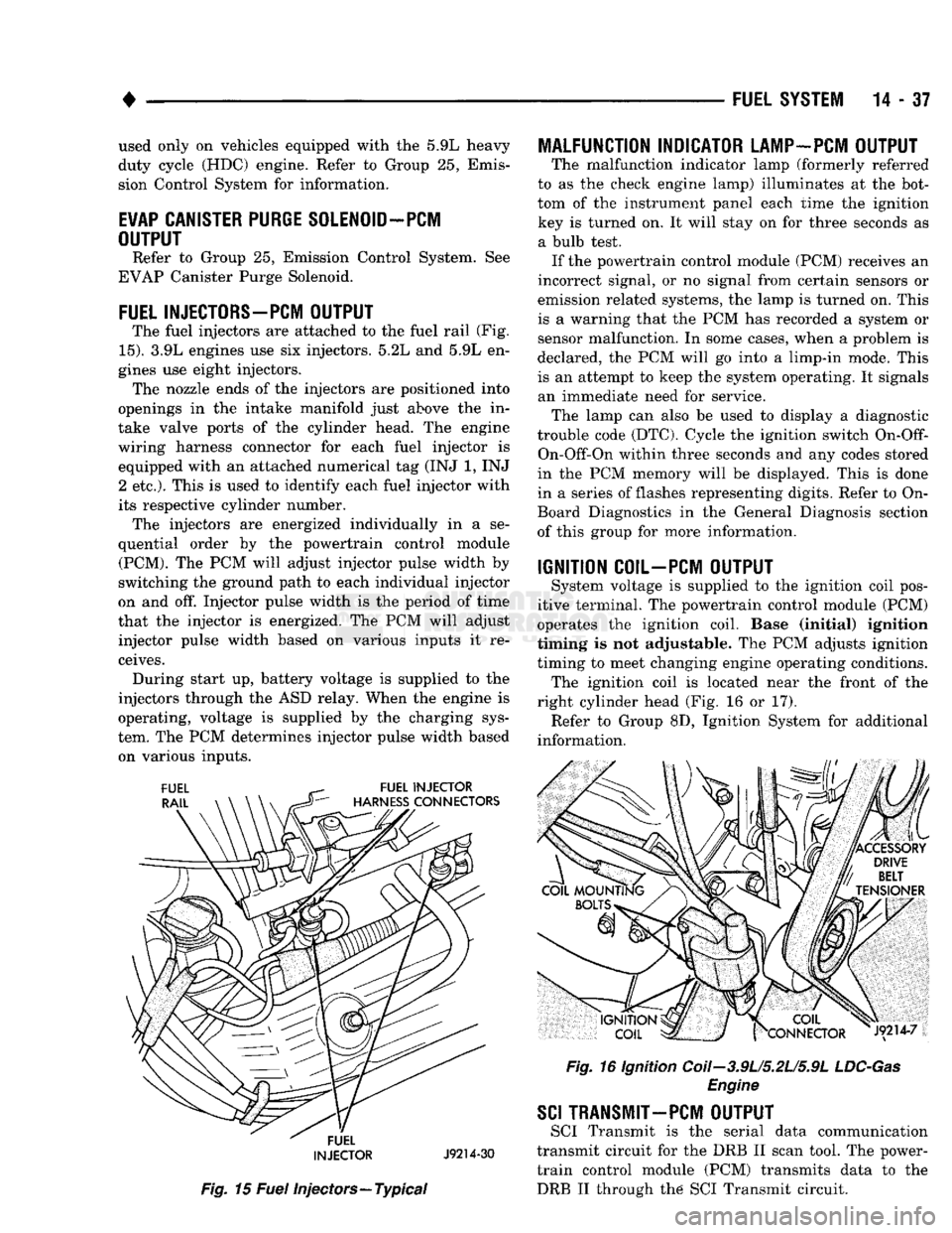
The fuel injectors are attached to the fuel rail (Fig.
15).
3.9L engines use six injectors. 5.2L and 5.9L en
gines use eight injectors. The nozzle ends of the injectors are positioned into
openings in the intake manifold just above the in
take valve ports of the cylinder head. The engine
wiring harness connector for each fuel injector is equipped with an attached numerical tag (INJ 1, INJ 2 etc.). This is used to identify each fuel injector with
its respective cylinder number. The injectors are energized individually in a se
quential order by the powertrain control module (PCM). The PCM will adjust injector pulse width by
switching the ground path to each individual injector
on and off. Injector pulse width is the period of time
that the injector is energized. The PCM will adjust injector pulse width based on various inputs it re
ceives. During start up, battery voltage is supplied to the
injectors through the ASD relay. When the engine is
operating, voltage is supplied by the charging sys
tem. The PCM determines injector pulse width based on various inputs.
FUEL
INJECTOR
J9214-30
Fig.
15
Fuel
injectors—Typical
MALFUNCTION INDICATOR LAMP-PCM OUTPUT
The malfunction indicator lamp (formerly referred
to as the check engine lamp) illuminates at the bot
tom of the instrument panel each time the ignition key is turned on. It will stay on for three seconds as a bulb test. If the powertrain control module (PCM) receives an
incorrect signal, or no signal from certain sensors or
emission related systems, the lamp is turned on. This
is a warning that the PCM has recorded a system or
sensor malfunction. In some cases, when a problem is
declared, the PCM will go into a limp-in mode. This
is an attempt to keep the system operating. It signals an immediate need for service. The lamp can also be used to display a diagnostic
trouble code (DTC). Cycle the ignition switch
On-Off-
On-Off-On within three seconds and any codes stored
in the PCM memory will be displayed. This is done
in a series of flashes representing digits. Refer to On-
Board Diagnostics in the General Diagnosis section
of this group for more information.
IGNITION COIL-PCM OUTPUT
System voltage is supplied to the ignition coil pos
itive terminal. The powertrain control module (PCM)
operates the ignition coil. Base (initial) ignition
timing is not adjustable. The PCM adjusts ignition
timing to meet changing engine operating conditions. The ignition coil is located near the front of the
right cylinder head (Fig. 16 or 17). Refer to Group 8D, Ignition System for additional
information.
Fig.
16 Ignition Coii-3.9U5.2U5.9L
LDC-Gas
Engine
SCI
TRANSMIT—PCM OUTPUT
SCI Transmit is the serial data communication
transmit circuit for the DRB II scan tool. The power- train control module (PCM) transmits data to the DRB II through the SCI Transmit circuit.
Page 857 of 1502
14 - 38
FUEL SYSTEM
•
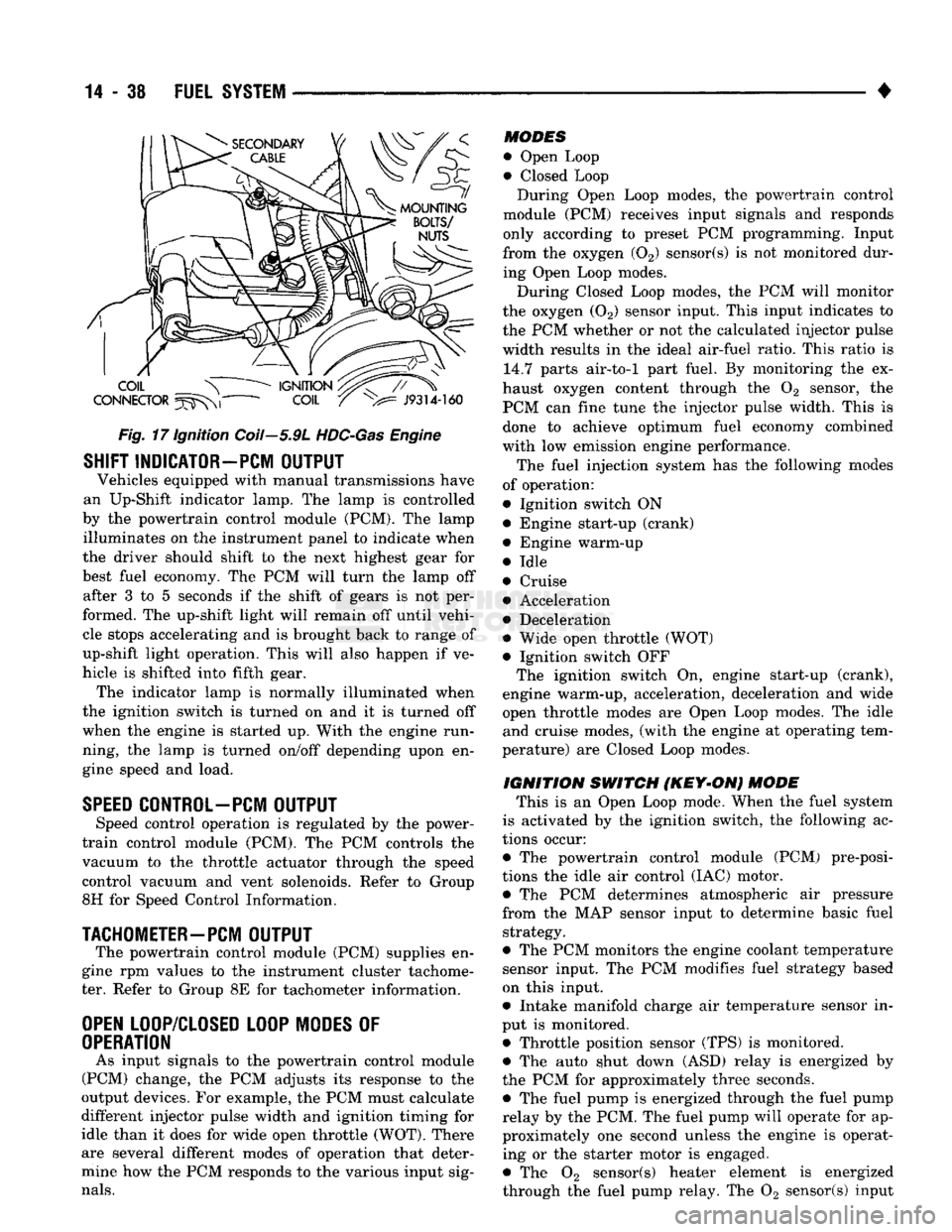
Fig.
17 Ignition Coil—5.9L
HDC-Gas
Engine
SHIFT INDICATOR-PCM
OUTPUT
Vehicles equipped with manual transmissions have
an Up-Shift indicator lamp. The lamp is controlled
by the powertrain control module (PCM). The lamp illuminates on the instrument panel to indicate when
the driver should shift to the next highest gear for
best fuel economy. The PCM will turn the lamp off after 3 to 5 seconds if the shift of gears is not per
formed. The up-shift light will remain off until vehi cle stops accelerating and is brought back to range of
up-shift light operation. This will also happen if ve
hicle is shifted into fifth gear. The indicator lamp is normally illuminated when
the ignition switch is turned on and it is turned off
when the engine is started up. With the engine run
ning, the lamp is turned on/off depending upon en
gine speed and load.
SPEED
CONTROL-PCM
OUTPUT
Speed control operation is regulated by the power-
train control module (PCM). The PCM controls the
vacuum to the throttle actuator through the speed
control vacuum and vent solenoids. Refer to Group
8H for Speed Control Information.
TACHOMETER—PCM
OUTPUT
The powertrain control module (PCM) supplies en
gine rpm values to the instrument cluster tachome ter. Refer to Group 8E for tachometer information.
OPEN
LOOP/CLOSED LOOP MODES
OF
OPERATION
As input signals to the powertrain control module
(PCM) change, the PCM adjusts its response to the
output devices. For example, the PCM must calculate
different injector pulse width and ignition timing for
idle than it does for wide open throttle (WOT). There
are several different modes of operation that deter
mine how the PCM responds to the various input sig
nals.
MODES
• Open Loop
• Closed Loop During Open Loop modes, the powertrain control
module (PCM) receives input signals and responds
only according to preset PCM programming. Input
from the oxygen (02) sensor(s) is not monitored dur
ing Open Loop modes.
During Closed Loop modes, the PCM will monitor
the oxygen (02) sensor input. This input indicates to
the PCM whether or not the calculated injector pulse width results in the ideal air-fuel ratio. This ratio is 14.7 parts air-to-1 part fuel. By monitoring the ex
haust oxygen content through the 02 sensor, the
PCM can fine tune the injector pulse width. This is done to achieve optimum fuel economy combined
with low emission engine performance.
The fuel injection system has the following modes
of operation:
• Ignition switch ON • Engine start-up (crank)
• Engine warm-up
• Idle
• Cruise • Acceleration
• Deceleration
• Wide open throttle (WOT)
• Ignition switch OFF The ignition switch On, engine start-up (crank),
engine warm-up, acceleration, deceleration and wide
open throttle modes are Open Loop modes. The idle and cruise modes, (with the engine at operating tem
perature) are Closed Loop modes.
IGNITION
SWITCH
(KEY-ON)
MODE
This is an Open Loop mode. When the fuel system
is activated by the ignition switch, the following ac
tions occur:
• The powertrain control module (PCM) pre-posi-
tions the idle air control (IAC) motor. • The PCM determines atmospheric air pressure
from the MAP sensor input to determine basic fuel strategy.
• The PCM monitors the engine coolant temperature sensor input. The PCM modifies fuel strategy based
on this input.
• Intake manifold charge air temperature sensor in
put is monitored.
• Throttle position sensor (TPS) is monitored. • The auto shut down (ASD) relay is energized by
the PCM for approximately three seconds. • The fuel pump is energized through the fuel pump
relay by the PCM. The fuel pump will operate for ap
proximately one second unless the engine is operat ing or the starter motor is engaged.
• The 02 sensor(s) heater element is energized
through the fuel pump relay. The 02 sensor(s) input