ECO mode DODGE TRUCK 1993 Service Manual PDF
[x] Cancel search | Manufacturer: DODGE, Model Year: 1993, Model line: TRUCK, Model: DODGE TRUCK 1993Pages: 1502, PDF Size: 80.97 MB
Page 1483 of 1502
25
- 6
EMISSION CONTROL
SYSTEMS
•
EWAPORATIWE EMISSION CONTROLS
INDEX
page
Crankcase
Breather/Filter—Gas Powered
Engines
. . . 9
EVAP
(Evaporation)
Control
System
. 6
EVAP
Canister
. . 6
page
Evap
Canister
Purge
Solenoid
6
Fuel Tank
Filler
Tube
Cap . 7
Positive
Crankcase
Ventilation
(PCV)
System
.... 7
Pressure
Relief/Rollover Valve
6
EVAP (EVAPORATION) CONTROL SYSTEM GENERAL
INFORMATION
The function
of the
EVAP control system
is to
pre
vent
the
emissions
of
gasoline vapors from
the
fuel
tank into
the
atmosphere. When fuel evaporates
in
the fuel tank,
the
vapors pass through vent hoses
or
tubes
to a
carbon filled EVAP canister. They
are
temporarily held
in the
canister until they
can be
drawn into
the
intake manifold when
the
engine
is
running.
The vapors
are
drawn into
the
engine
at
idle
as
well
as off
idle. This system
is
called
a
Bi-level Purge
System where there
is a
dual source
of
vacuum
to re
move fuel vapor from
the
EVAP canister. The EVAP canister
is a
feature
on all
models
for
the storage
of
fuel vapors from
the
fuel tank.
The hoses used
in
this system
are
specially
manufactured.
If
replacement becomes neces sary,
it is
important
to use
only fuel resistant
hose.
PRESSURE
RELIEF/ROLLOVER VALVE
These vehicles
are
equipped with
a
combination
pressure relief
and
rollover valve. This dual function valve will relieve fuel tank pressure
and
also prevent
fuel flow through
the
fuel tank vent hoses
in the
event
of an
accidental vehicle rollover. The valve incorporates
a
pressure relief mechanism
that releases fuel tank pressure when
the
pressure increases above
the
calibrated sealing value. Refer
to
the Fuel Tank section
of
Group
14,
Fuel Systems
for
removal
and
installation procedures.
EVAP CANISTER
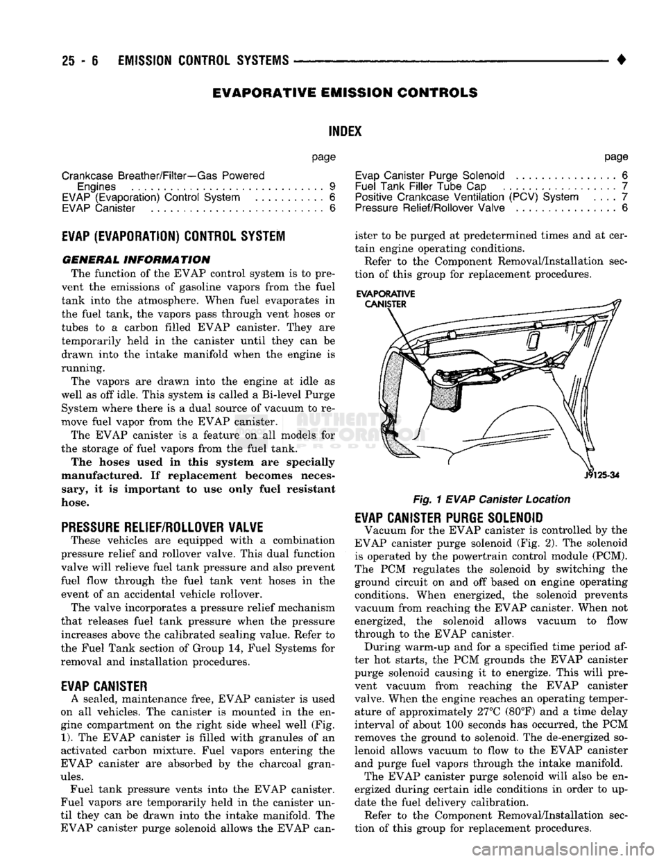
A sealed, maintenance free, EVAP canister
is
used
on
all
vehicles.
The
canister
is
mounted
in the en
gine compartment
on the
right side wheel well
(Fig.
1).
The
EVAP canister
is
filled with granules
of an
activated carbon mixture. Fuel vapors entering
the
EVAP canister
are
absorbed
by the
charcoal gran
ules.
Fuel tank pressure vents into
the
EVAP canister.
Fuel vapors
are
temporarily held
in the
canister
un
til they
can be
drawn into
the
intake manifold.
The
EVAP canister purge solenoid allows
the
EVAP can ister
to be
purged
at
predetermined times
and at
cer
tain engine operating conditions.
Refer
to the
Component Removal/Installation sec
tion
of
this group
for
replacement procedures.
EVAPORATIVE
Fig.
1
EVAP
Canister Location
EVAP CANISTER PURGE SOLENOID
Vacuum
for the
EVAP canister
is
controlled
by the
EVAP canister purge solenoid
(Fig. 2). The
solenoid
is operated
by the
powertrain control module (PCM).
The
PCM
regulates
the
solenoid
by
switching
the
ground circuit
on and off
based
on
engine operating conditions. When energized,
the
solenoid prevents
vacuum from reaching
the
EVAP canister. When
not
energized,
the
solenoid allows vacuum
to
flow
through
to the
EVAP canister. During warm-up
and for a
specified time period
af
ter
hot
starts,
the PCM
grounds
the
EVAP canister purge solenoid causing
it to
energize. This will pre
vent vacuum from reaching
the
EVAP canister
valve. When
the
engine reaches
an
operating temper ature
of
approximately 27°C (80°F)
and a
time delay
interval
of
about
100
seconds
has
occurred,
the PCM
removes
the
ground
to
solenoid.
The
de-energized
so
lenoid allows vacuum
to
flow
to the
EVAP canister and purge fuel vapors through
the
intake manifold. The EVAP canister purge solenoid will also
be en
ergized during certain idle conditions
in
order
to up
date
the
fuel delivery calibration. Refer
to the
Component Removal/Installation sec
tion
of
this group
for
replacement procedures.