frame DODGE TRUCK 1993 Service Owner's Guide
[x] Cancel search | Manufacturer: DODGE, Model Year: 1993, Model line: TRUCK, Model: DODGE TRUCK 1993Pages: 1502, PDF Size: 80.97 MB
Page 484 of 1502
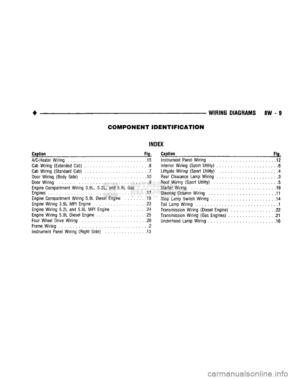
COMPONENT
IDENTIFICATION
INDEX
Caption
Fig.
A/C-Heater
Wiring
15
Cab
Wiring (Extended
Cab)
8
Cab
Wiring (Standard Cab)
7
Door
Wiring (Body
Side)
10
Door
Wiring
9
Engine
Compartment Wiring
3.9L,
5.2L, and 5.9L
Gas
Engines
.17
Engine
Compartment Wiring
5.9L
Diesel
Engine
. 18
Engine
Wiring
3.9L
MPI
Engine
23
Engine
Wiring
5.2L
and 5.9L
MPI
Engine
24
Engine
Wiring
5.9L
Diesel
Engine
25
Four
Wheel Drive Wiring
.20
Frame
Wiring
2
Instrument Panel Wiring (Right
Side)
13
Caption
Fig^
Instrument Panel Wiring
12
Interior
Wiring (Sport
Utility)
6
Liftgate
Wiring (Sport
Utility)
......
4
Rear
Clearance Lamp Wiring
3
Roof
Wiring (Sport
Utility)
5
Starter Wiring
19
Steering
Column Wiring
. 11
Stop
Lamp Switch Wiring
. 14
Tail
Lamp Wiring
1
Transmission
Wiring (Diesel Engine)
. .22
Transmission
Wiring (Gas
Engines)
21
Underhood
Lamp Wiring
. .16
Page 486 of 1502
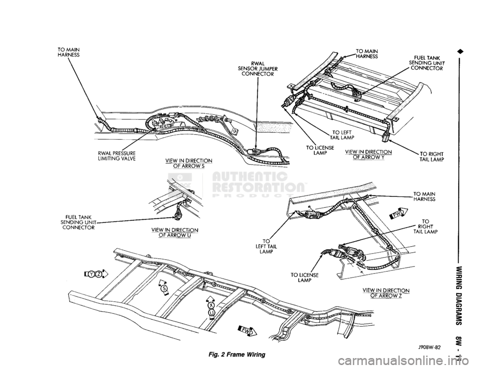
J908W-82
Fig.
2 Frame Wiring
Page 548 of 1502
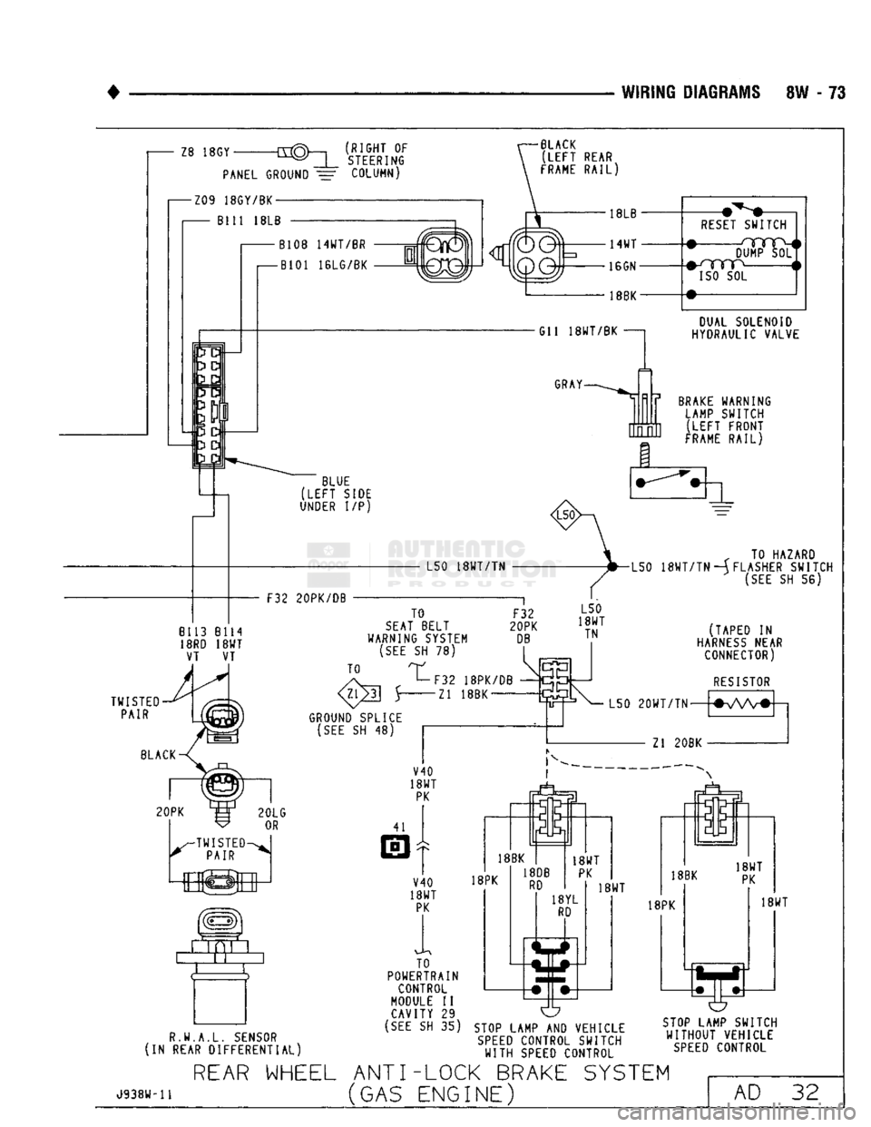
WIRING DIAGRAMS SW - 73
(RIGHT OF
STEERING
BLACK
(LEFT
REAR
FRAME
RAIL)
RESET
SWITCH DUMP SOL
#-/YYTP
i
ISO
SOL
DUAL SOLENOID
HYDRAULIC VALVE
BRAKE
WARNING LAMP SWITCH ;LEFT FRONT
FRAME
RAIL)
„ TO HAZARD
L50
18WT/TN
—(FLASHER SWITCH
(SEE
SH 56)
R.W.A.L.
SENSOR
(IN REAR DIFFERENTIAL) TO
POWERTRAIN
CONTROL
MODULE II CAVITY 29
(SEE
SH 35) O
STOP
LAMP AND VEHICLE
SPEED
CONTROL SWITCH
WITH
SPEED
CONTROL
STOP
LAMP SWITCH
WITHOUT
VEHICLE
SPEED
CONTROL
J938W-11
REAR
WHEEL ANTI-LOCK BRAKE SYSTEM
(GAS ENGINE) AD 32
Page 550 of 1502
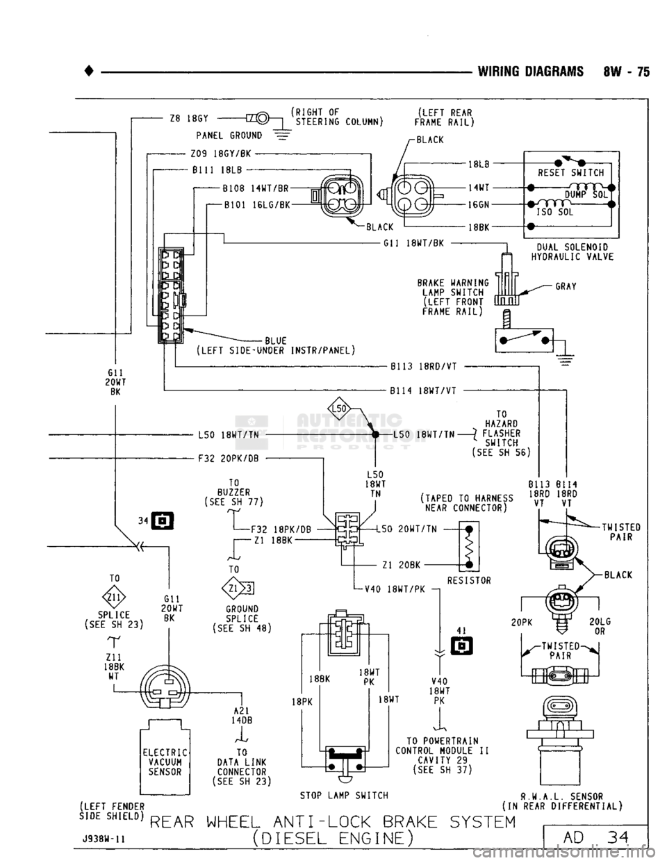
WIRING
DIAGRAMS
8W - 75
Z8
18GY
PANEL
GROUND
Z09 18GY/BK
Bill
18LB -
_rrrRv_
(RIGHT 0F
~LL1U)
|
STEERING COLUMN)
(LEFT
REAR
FRAME
RAIL)
BLACK
B108 14WT/BR
-j=rf
B101 16LG/BK
-BLACK
18BK-
G11 18WT/BK
RESET
SWITCH
DUMP
ISO
SOL
BRAKE
WARNING
LAMP SWITCH
(LEFT
FRONT
FRAME
RAIL) DUAL SOLENOID
HYDRAULIC VALVE
GRAY
Gil
20WT
BK
BLUE
(LEFT
SIDE-UNDER INSTR/PANEL)
• • L50
18WT/TN
F32 20PK/DB
TO
BUZZER
(SEE
SH 77)
GROUND
SPLICE
(SEE
SH 48)
Bl13
18RD/VT
B114
18WT/VT
TO
HAZARD
L50
18WT/TN
?
FLASHER ^ SWITCH
(SEE
SH 56)
(TAPED
TO
HARNESS
NEAR
CONNECTOR) 8113
Bl14
18RD
18RD
VT
VT
F32 18PK/DB Zl
18BK 150
20WT/TN
Zl 20BK
V40
18WT/PK
TO
DATA LINK CONNECTOR
(SEE
SH 23)
RESISTOR
41
20PK
18WT V40
18WT
PK
i TO POWERTRAIN
CONTROL MODULE
II
CAVITY
29
(SEE
SH 37)
TWISTED
PAIR
BLACK
STOP
LAMP SWITCH
(LEFT FENDER
SIDE
SHIELD)
REAR WHEEL
ANT
I
-LOCK BRAKE SYSTEM
U938w-ii
(DIESEL ENGINE) R.W.A.L. SENSOR
(IN REAR DIFFERENTIAL)
AD
34
Page 596 of 1502
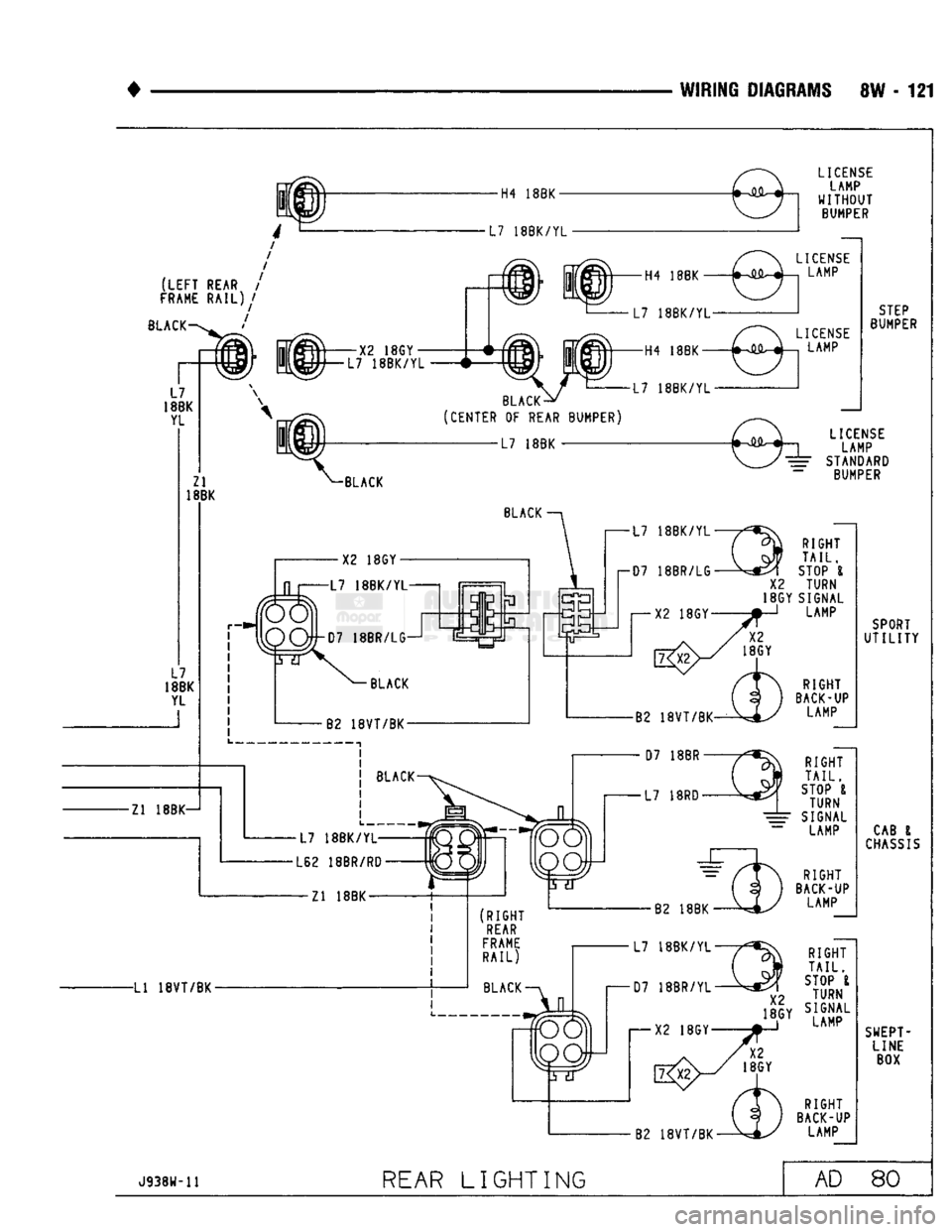
WIRING DIAGRAMS SW - 121
H4 18BK-
(LEFT
REAR /
FRAME RAIL)/
BLACK ' L7
18BK
YL Zl
18BK—1
LI
18VT/BK-
H4 18BK
X2 18GY
18BK/YL
L7
18BK/YL-
H4
18BK—
BLACK-
(CENTER OF REAR BUMPER) L7
18BK/YL-
BLACK
X2 18GY -L7 18BK
BLACK
L62 18BR/RD•
— Zl 18BK — LICENSE
LAMP
WITHOUT
BUMPER LICENSE
LAMP
LICENSE LAMP STEP
BUMPER
LICENSE LAMP
^ STANDARD BUMPER
RIGHT
TAIL.
STOP I
X2
TURN
18GY SIGNAL LAMP
B2
18VT/BK-
RIGHT
BACK-UP LAMP
RIGHT
TAIL.
STOP I
TURN
SIGNAL LAMP
RIGHT
BACK-UP LAMP
RIGHT
TAIL.
STOP I
TURN
SIGNAL
LAMP
RIGHT
BACK-UP LAMP SPORT
UTILITY
CAB
I
CHASSIS
SWEPT LINE
BOX
J938W-11
REAR
LIGHTING AD 80
Page 623 of 1502
9
- 18 3.9L
ENGINE
• (2) Raise hood and position fan to assure clearance
for radiator top tank and hose.
CAUTION:
DO NOT
lift
the engine by the
intake
manifold.
(3) Install engine lifting fixture.
(4) Raise vehicle on hoist.
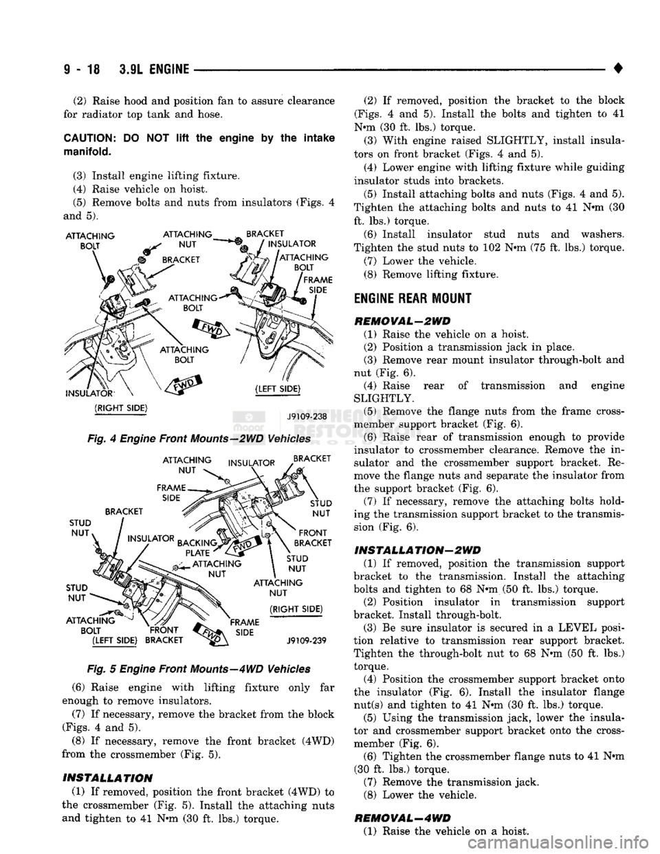
(5) Remove bolts and nuts from insulators (Figs. 4
and 5).
ATTACHING
BOLT
ATTACHING
NUT
BRACKET
INSULATOR
ATTACHING
BOLT
FRAME
SIDE
INSULATOR?
(RIGHT
SIDE)
(LEFT
SIDE)
J9109-238
Fig.
4
Engine
Front
Mounts—2WD
Vehicles
ATTACHING
NUT
FRAME
SIDE
INSULATOR
BRACKET
STUD
NUT»
STUD NUT
ATTACHING
BOLT INSULATOR
BACKING.
PLATE
ATTACHING
NUT
BRACKET
STUD NUT
FRONT
BRACKET
STUD NUT
ATTACHING
NUT
FRAME
s,de
(RIGHT
SIDE)
J9109-239
Fig.
5
Engine
Front
Mounts—4WD
Vehicles
(6) Raise engine with lifting fixture only far
enough to remove insulators.
(7) If necessary, remove the bracket from the block
(Figs.
4 and 5).
(8) If necessary, remove the front bracket (4WD)
from the crossmember (Fig. 5).
INSTALLATION (1) If removed, position the front bracket (4WD) to
the crossmember (Fig. 5). Install the attaching nuts and tighten to 41 N»m (30 ft. lbs.) torque. (2) If removed, position the bracket to the block
(Figs.
4 and 5). Install the bolts and tighten to 41
N*m (30 ft. lbs.) torque. (3) With engine raised SLIGHTLY, install insula
tors on front bracket (Figs. 4 and 5).
(4) Lower engine with lifting fixture while guiding
insulator studs into brackets.
(5) Install attaching bolts and nuts (Figs. 4 and 5).
Tighten the attaching bolts and nuts to 41 N«m (30 ft. lbs.) torque,
(6) Install insulator stud nuts and washers.
Tighten the stud nuts to 102 N»m (75 ft. lbs.) torque.
(7) Lower the vehicle.
(8) Remove lifting fixture.
ENGINE
REAR
MOUNT
REMOVAL-2WD (1) Raise the vehicle on a hoist. (2) Position a transmission jack in place.
(3) Remove rear mount insulator through-bolt and
nut (Fig. 6). (4) Raise rear of transmission and engine
SLIGHTLY.
(5) Remove the flange nuts from the frame cross-
member support bracket (Fig. 6). (6) Raise rear of transmission enough to provide
insulator to crossmember clearance. Remove the in sulator and the crossmember support bracket. Re
move the flange nuts and separate the insulator from
the support bracket (Fig. 6).
(7) If necessary, remove the attaching bolts hold
ing the transmission support bracket to the transmis
sion (Fig. 6).
INSTALLA
TION-2WD
(1) If removed, position the transmission support
bracket to the transmission. Install the attaching
bolts and tighten to 68 N*m (50 ft. lbs.) torque.
(2) Position insulator in transmission support
bracket. Install through-bolt.
(3) Be sure insulator is secured in a LEVEL posi
tion relative to transmission rear support bracket.
Tighten the through-bolt nut to 68 N*m (50 ft. lbs.) torque.
(4) Position the crossmember support bracket onto
the insulator (Fig. 6). Install the insulator flange nut(s) and tighten to 41 Nnn (30 ft. lbs.) torque.
(5) Using the transmission jack, lower the insula
tor and crossmember support bracket onto the cross- member (Fig. 6).
(6) Tighten the crossmember flange nuts to 41 Nnn
(30 ft. lbs.) torque.
(7) Remove the transmission jack.
(8) Lower the vehicle.
HE MO
VAL—4
WD (1) Raise the vehicle on a hoist.
Page 653 of 1502
9
• 48 5.2L
ENGINE
•
CAUTION;
DO NOT lift the
engine
by the
intake
manifold.
(2) Install an engine lifting fixture.
(3) Raise vehicle on hoist.
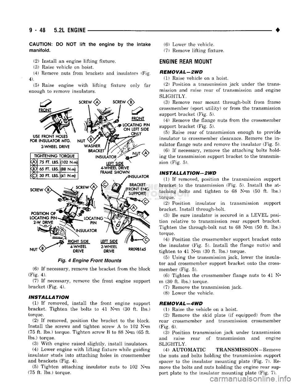
(4) Remove nuts from brackets and insulators (Fig.
4).
(5) Raise engine with lifting fixture only far
enough to remove insulators.
SCREW
<£>
SCREW
<1j>
FRONT
LOCATING PIN
" ON LEFT
SIDE
ONLY
USE
FRONT HOLES
FOR
INSULATOR MTG,
2-WHEEL DRIVE TIGHTENING TORQUE
75
FT. LBS. (102 N-m)
65 FT. LBS. (88 N.m)
<£>
30 FT. LBS.
(41
N-m)
NUT
WASHER
BRACKET'
INSULATOR
<
LEFTSIDE
4-WHEEL DRIVE
FRAME SHOWN INSULATOR
BRACKET
(FRONT ENG SUPPORT)
Fig.
4
Engine
Front
Mounts
(6) If necessary, remove the bracket from the block
(Fig. 4).
(7) If necessary, remove the front engine support
bracket (Fig. 4).
INSTALLATION (1) If removed, install the front engine support
bracket. Tighten the bolts to 41 N-m (30 ft. lbs.)
torque.
(2) If removed, position the bracket to the block.
Install the screws and tighten screw A to 102 N-m (75 ft. lbs.) torque. Tighten screw B to 88 N-m (65 ft.
lbs.) torque.
(3) With engine raised slightly, install insulators.
(4) Lower engine with lifting fixture while guiding
insulator studs into attaching holes in crossmember
and brackets (Fig. 4). (5) Tighten attaching insulator nuts to 102 N-m
(75 ft. lbs.) torque. (6) Lower the vehicle.
(7) Remove lifting fixture.
ENGINE REAR
MOUNT
REMOVAL-2WD (1) Raise vehicle on a hoist.
(2) Position a transmission jack under the trans
mission and raise rear of transmission and engine
SLIGHTLY. (3) Remove rear mount through-bolt from frame
crossmember (sport utility) or from the transmission support bracket (Fig. 5). (4) Remove the flange nuts from the crossmember
support bracket (Fig. 5).
(5) Raise rear of transmission enough to provide
insulator to crossmember clearance. Remove the in
sulator flange nuts and remove the insulator (Fig. 5). (6) If necessary, remove the attaching bolts hold
ing the transmission support bracket to the transmis
sion (Fig. 5).
INSTALLATION-2WD (1) If removed, position the transmission support
bracket to the transmission (Fig. 5). Install the at taching bolts and tighten to 68 N-m (50 ft. lbs.)
torque.
(2) Position insulator in transmission support
bracket. Install through-bolt.
(3) Be sure insulator is secured in a LEVEL posi
tion relative to transmission rear support bracket.
Tighten the through-bolt nut to 68 N-m (50 ft. lbs.) torque.
(4) Position the crossmember support bracket onto
the insulator (Fig. 5). Install the flange nut(s) and
tighten to 41 N-m (30 ft. lbs.) torque.
(5) Using the transmission jack, lower the insula
tor and crossmember support bracket onto the cross-
member (Fig. 5).
(6) Tighten the crossmember flange nuts to 41 N-
m (30 ft. lbs.) torque. (7) Remove the transmission jack. (8) Lower the vehicle.
REMOVAL-4WD (1) Raise the vehicle on a hoist.
(2) Remove the skid plate (if equipped) from the
rear crossmember and transmission crossmember (Fig. 6). (3) Position transmission jack under transmission
and raise rear of transmission and engine
SLIGHTLY. (4) AUTOMATIC TRANSMISSION-Remove
the nuts and bolts holding the transmission support spacer to the insulator mounting plate (Fig. 7). Re
move the bolts and nuts holding the engine rear sup
port plate to the insulator mounting plate (Fig. 7).
Page 683 of 1502
9
- 78 5.9L ENGINE
•
CAUTION:
DO NOT
lift
the engine by the
intake
manifold.
(2)
Install an engine lifting fixture.
(3) Raise vehicle on hoist.
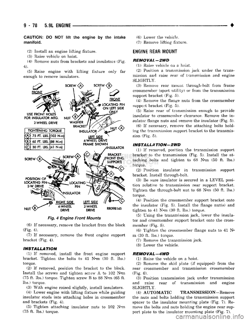
(4) Remove nuts from brackets and insulators (Fig,
4).
(5) Raise engine with lifting fixture only far
enough to remove insulators.
SCREW
<£>
SCREW
FRONT
#C3p
LOCATING
PIN
- -•- —
SIDE
ONLY
INSULATORS
^
4-WHEEL DRIVE
FRAME
SHOWN
INSULATOR
BRACKET
(FRONT
ENG
SUPPORT)
USE
FRONT
HOLES
FOR
INSULATOR
MTG.
2-WHEEL DRIVE
TIGHTENING TORQUE
75
FT.
LBS.
(102 N-m)
65
FT.
LBS.
(38
Hw)
<£) 30
FT.
LBS.
(41
N-m)
RIGHT
SIDE
4-WHEEL
DRIVE
LEFT
SIDE
2-WHEEL
DRIVE
RR09B145
Fig.
4 Engine Front
Mounts
(6) If necessary, remove the bracket from the block
(Fig. 4).
(7)
If necessary, remove the front engine support
bracket (Fig. 4).
INSTALLATION
(1) If removed, install the front engine support
bracket. Tighten the bolts to 41 N-m (30 ft. lbs.)
torque.
(2) If removed, position the bracket to the block.
Install the screws and tighten screw A to 102 Nrn (75 ft. lbs.) torque. Tighten screw B to 88 N-m (65 ft.
lbs.) torque.
(3) With engine raised slightly, install insulators.
(4) Lower engine with lifting fixture while guiding
insulator studs into attaching holes in crossmember and brackets (Fig. 4). (5) Tighten attaching insulator nuts to 102 N-m
(75 ft. lbs.) torque. (6) Lower the vehicle.
(7)
Remove lifting fixture.
engine rear
MOUNT
REMCYAL-2WD (1) Raise vehicle on a hoist.
(2) Position a transmission jack under the trans
mission and raise rear of transmission and engine SLIGHTLY.
(3) Remove rear mount through-bolt from frame
crossmember (sport utility) or from the transmission support bracket (Fig. 5).
(4) Remove the flange nuts from the crossmember
support bracket (Fig. 5).
(5) Raise rear of transmission enough to provide
insulator to crossmember clearance. Remove the in
sulator flange nuts and remove the insulator (Fig. 5).
(6) If necessary, remove the attaching bolts hold
ing the transmission support bracket to the transmis sion (Fig. 5).
INSTALLATION-2WD (1) If removed, position the transmission support
bracket to the transmission (Fig. 5). Install the at
taching bolts and tighten to 68 N-m (50 ft. lbs.) torque. (2) Position insulator in transmission support
bracket. Install through-bolt.
(3) Be sure insulator is secured in a LEVEL posi
tion relative to transmission rear support bracket. Tighten the through-bolt nut to 68 N-m (50 ft. lbs.) torque.
(4) Position the crossmember support bracket onto
the insulator (Fig. 5). Install the flange nut(s) and
tighten to 41 N-m (30 ft. lbs.) torque.
(5)
Using the transmission jack, lower the insula
tor and crossmember support bracket onto the cross-
member (Fig. 5).
(6) Tighten the crossmember flange nuts to 41 N-
m (30 ft. lbs.) torque. (7) Remove the transmission jack.
(8) Lower the vehicle.
REMOVAL-4WD
(1) Raise the vehicle on a hoist.
(2) Remove the skid plate (if equipped) from the
rear crossmember and transmission crossmember (Fig. 6). (3) Position transmission jack under transmission
and raise rear of transmission and engine
SLIGHTLY. (4) AUTOMATIC TRANSMISSION-Remove
the nuts and bolts holding the transmission support spacer to the insulator mounting plate (Fig. 7). Re
move the bolts and nuts holding the engine rear sup
port plate to the insulator mounting plate (Fig. 7).
Page 766 of 1502
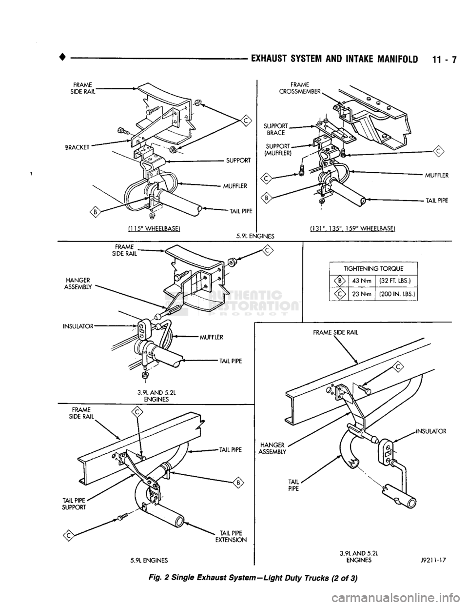
•
EXHAUST
SYSTEM
AND
INTAKE MANIFOLD
11-7
INSULATOR
FRAME
SIDE
RAIL
3.9L
AND
5.2L
ENGINES
TAIL
PIPE
TAIL
PIPE
TAIL
PIPE
EXTENSION
5.9L
ENGINES HANGER
ASSEMBLY
TAIL
PIPE
FRAME
SIDE RAIL
INSULATOR
3.9L
AND
5.2L
ENGINES
J9211-17
Fig. 2 Single Exhaust System—Light Duty Trucks (2 of 3)
Page 769 of 1502
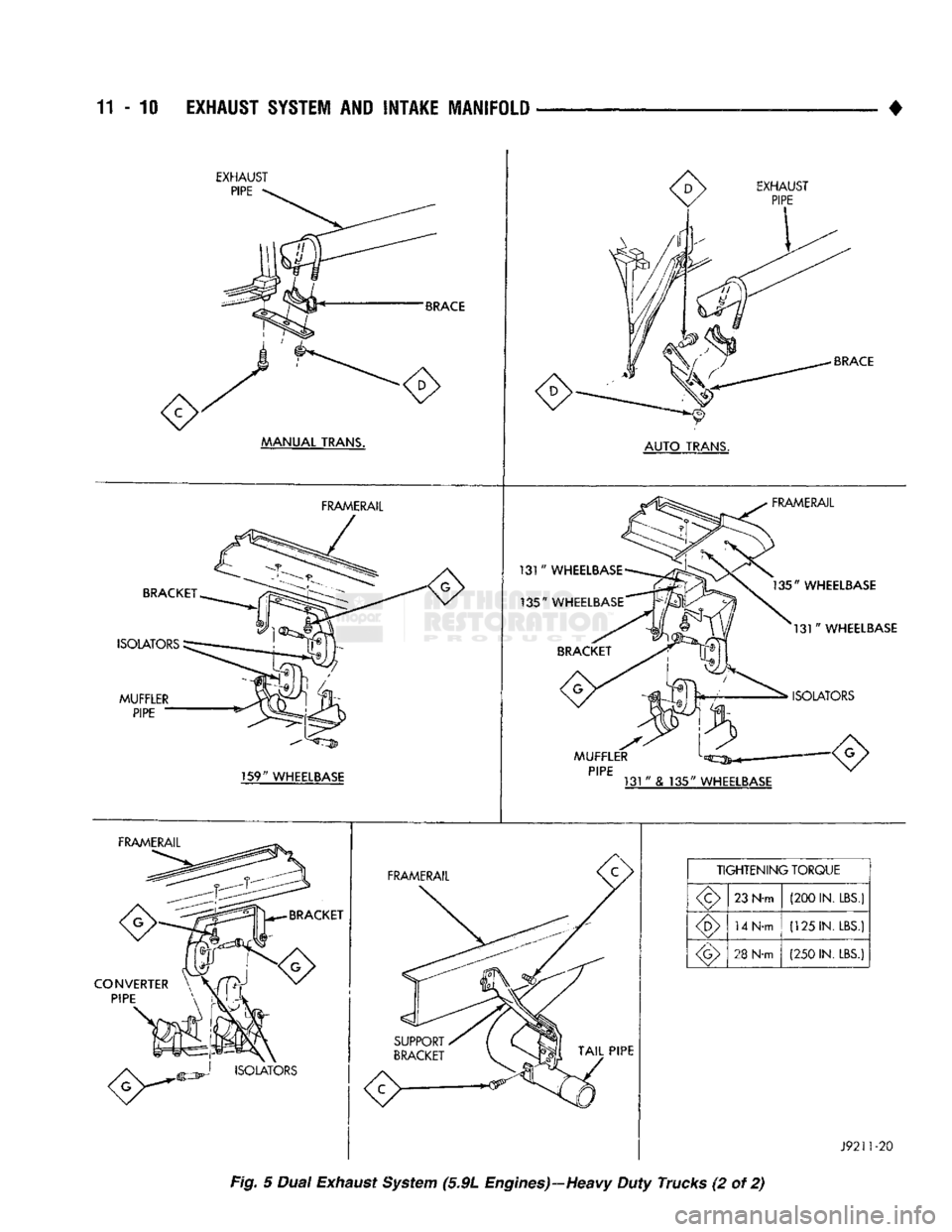
11
- 10
EXHAUST SYSTEM
AND
INTAKE MANIFOLD
EXHAUST
PIPE
BRACE
MANUAL
TRANS. EXHAUST
PIPE
BRACE
AUTO
TRANS.
BRACKET
ISOLATORS
MUFFLER
PIPE
FRAMERAIL
131
"
WHEELBASE
135"
WHEELBASE
FRAMERAIL
135"
WHEELBASE
131"
WHEELBASE
ISOLATORS
159"
WHEELBASE
MUFFLER
PIPE
131
"
& 135"
WHEELBASE
FRAMERAIL
BRACKET
CONVERTER PIPE
FRAMERAIL
TIGHTENING
TORQUE
23 N-m (200 IN.
LBS.)
14 N-m (125 IN.
LBS.)
28
N-m (250 IN.
LBS.)
J9211-20
Fig. 5 Dual Exhaust System (5.9L Engines)—Heavy Duty Trucks (2 of 2)