battery location DODGE TRUCK 1993 Service Repair Manual
[x] Cancel search | Manufacturer: DODGE, Model Year: 1993, Model line: TRUCK, Model: DODGE TRUCK 1993Pages: 1502, PDF Size: 80.97 MB
Page 356 of 1502
•
IGNITION
SYSTEMS
8D - 5
THROTTLE
^
BODY
u
BRACKET
y^SUPPORT
BRACKET
/ |
CHARGE
AIR
ijmmmmk
TEMPERATURE
SENSOR
THROTTLE
BODY
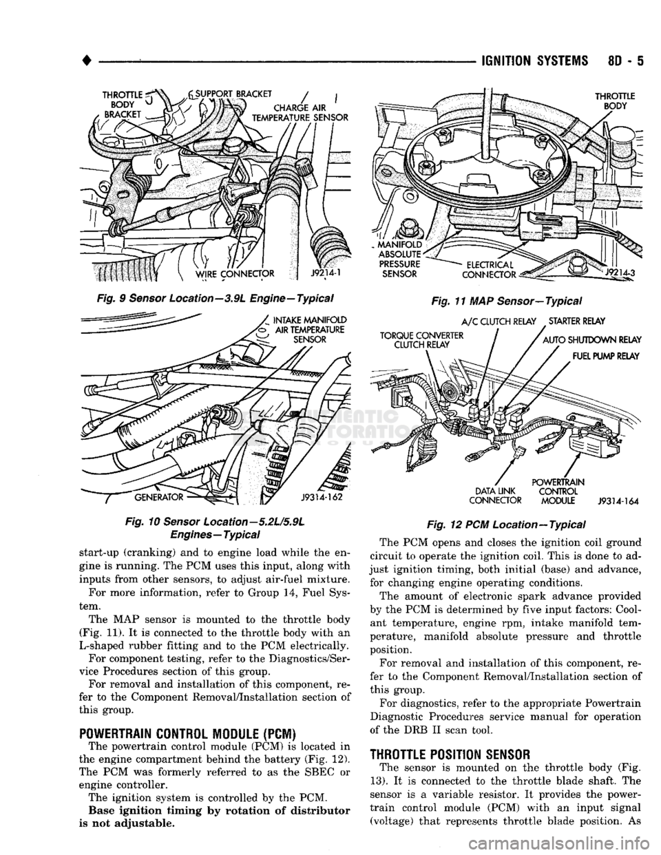
Fig.
9
Sensor
Location—3.9L Engine—Typical
INTAKE MANIFOLD
'b AIR TEMPERATURE
SENSOR
J9314-162
Fig.
10
Sensor
Location—5.2L/5.9L
Engines—Typical
start-up (cranking) and to engine load while the en
gine is running. The PCM uses this input, along with
inputs from other sensors, to adjust air-fuel mixture.
For more information, refer to Group 14, Fuel Sys
tem.
The MAP sensor is mounted to the throttle body
(Fig. 11). It is connected to the throttle body with an
L-shaped rubber fitting and to the PCM electrically. For component testing, refer to the Diagnostics/Ser
vice Procedures section of this group. For removal and installation of this component, re
fer to the Component Removal/Installation section of
this group.
POWERTRAIN CONTROL MODULE
(PCM) The powertrain control module (PCM) is located in
the engine compartment behind the battery (Fig. 12).
The PCM was formerly referred to as the SBEC or engine controller. The ignition system is controlled by the PCM. Base ignition timing by rotation of distributor
is not adjustable.
MANIFOLD
ABSOLUTE
PRESSURE
SENSOR
TORQUE CONVERTER CLUTCH RELAY
ELECTRICAL
Jlp^
CONNECTOR
^gis!—
Fig.
11 MAP Sensor—Typical
A/C
CLUTCH RELAY STARTER RELAY
AUTO
SHUTDOWN RELAY FUEL PUMP RELAY
DATA LINK
CONNECTOR POWERTRAIN
CONTROL
MODULE
J9314-164
Fig.
12 PCM Location—Typical The PCM opens and closes the ignition coil ground
circuit to operate the ignition coil. This is done to ad
just ignition timing, both initial (base) and advance, for changing engine operating conditions.
The amount of electronic spark advance provided
by the PCM is determined by five input factors: Cool ant temperature, engine rpm, intake manifold tem
perature, manifold absolute pressure and throttle
position.
For removal and installation of this component, re
fer to the Component Removal/Installation section of
this group.
For diagnostics, refer to the appropriate Powertrain
Diagnostic Procedures service manual for operation
of the DRB II scan tool.
THROTTLE
POSITION
SENSOR
The sensor is mounted on the throttle body (Fig.
13).
It is connected to the throttle blade shaft. The
sensor is a variable resistor. It provides the power-
train control module (PCM) with an input signal (voltage) that represents throttle blade position. As
Page 373 of 1502
8D
- 22
IGNITION
SYSTEMS
• (1) Disconnect the wiring and secondary cable from
the ignition coil (Figs. 9 or 10).
WARNING:
(3.9L/5.2L/5.9L
LDC-GAS ENGINES)
DO
NOT REMOVE
THE
COIL MOUNTING BRACKET-TO-
CYLINDER HEAD MOUNTING BOLTS.
THE
COIL MOUNTING BRACKET
IS
UNDER ACCESSORY
DRIVE BELT TENSION.
IF
THIS BRACKET
IS TO BE
REMOVED
FOR ANY
REASON,
ALL
BELT TENSION
MUST FIRST
BE
RELIEVED. REFER
TO THE
BELT
SECTION
OF
GROUP
7,
COOLING SYSTEM.
(2) Remove ignition coil from coil mounting
bracket (two bolts).
INSTALLATION (1) Install the ignition coil to coil bracket. If nuts
and bolts are used to secure coil to coil bracket,
tighten to 11 N«m (100 in. lbs.) torque. If the coil mounting bracket has been tapped for coil mounting
bolts,
tighten bolts to 5 N«m (50 in. lbs.) torque.
(2) Connect all wiring to ignition coil.
INTAKE MANIFOLD CHARGE
AIR
TEMPERATURE
SENSOR
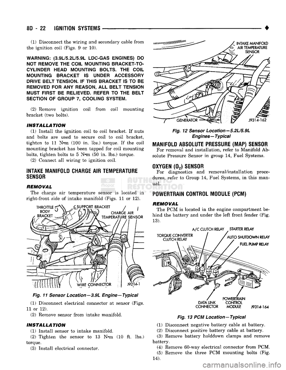
REMOVAL The charge air temperature sensor is located in
right-front side of intake manifold (Figs. 11 or 12).
Fig.
11
Sensor
Location—3.9L Engine—Typical
(1) Disconnect electrical connector at sensor (Figs.
11 or 12).
(2) Remove sensor from intake manifold.
INSTALLATION (1) Install sensor to intake manifold. (2) Tighten the sensor to 13 N-m (10 ft. lbs.)
torque. (3) Install electrical connector.
Fig.
12
Sensor
Location—5.2L/5.9L
Engines—Typical
MANIFOLD ABSOLUTE
PRESSURE
(MAP)
SENSOR
For removal and installation, refer to Manifold Ab
solute Pressure Sensor in group 14, Fuel Systems.
OXYGEN
(02)
SENSOR
For diagnostics and removal/installation proce
dures,
refer to Group 14, Fuel Systems, in this man
ual.
POWERTRAIN CONTROL MODULE
(PCM)
REMOVAL The PCM is located in the engine compartment be
hind the battery and under the left front fender (Fig.
13).
DATA
UNK CONTROL
CONNECTOR MODULE
J9314-164
Fig.
13 PCM Location—Typical (1) Disconnect negative battery cable at battery.
(2) Disconnect positive battery cable at battery.
(3) Remove battery holddown clamps and remove
battery.
(4) Remove 60-way electrical connector from PCM.
(5) Remove the three PCM mounting bolts (Fig.
14).
Page 377 of 1502
8D
- 28
IGNITION
SYSTEMS
SMALL
SCREWDRIVER
KEY
CYLINDER
RETAINING
PIN
KEY
CYLINDER
RETAINING
PIN
IGNITION SWITCH
908D-15
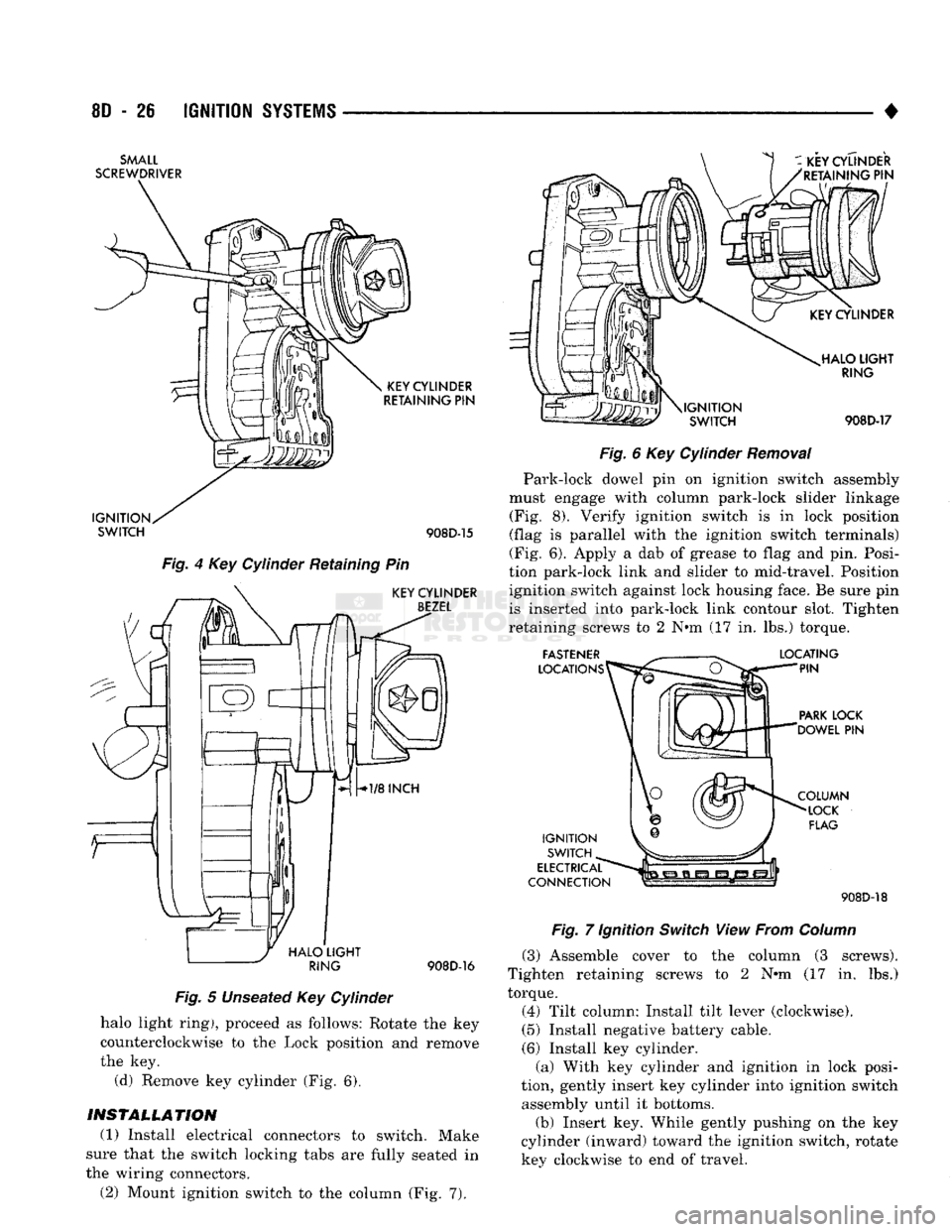
Fig.
4 Key Cylinder Retaining Pin
KEY
CYLINDER
BEZEL
j
HALO
LIGHT
^
RING
908D-16
Fig.
5 Unseated Key Cylinder
halo light ring), proceed as follows: Rotate the key
counterclockwise to the Lock position and remove
the key. (d) Remove key cylinder (Fig. 6).
INSTALLATION
(1) Install electrical connectors to switch. Make
sure that the switch locking tabs are fully seated in
the wiring connectors. (2) Mount ignition switch to the column (Fig. 7).
i-i-ii
\IGNITION
SWITCH HALO
LIGHT
RING
908D-17
Fig.
6 Key Cylinder
Removal
Park-lock dowel pin on ignition switch assembly
must engage with column park-lock slider linkage (Fig. 8). Verify ignition switch is in lock position
(flag is parallel with the ignition switch terminals)
(Fig. 6). Apply a dab of grease to flag and pin. Posi
tion park-lock link and slider to mid-travel. Position ignition switch against lock housing face. Be sure pin
is inserted into park-lock link contour slot. Tighten
retaining screws to 2 N#m (17 in. lbs.) torque.
FASTENER
LOCATIONS LOCATING
PIN
PARK
LOCK
'DOWEL
PIN
IGNITION SWITCH
ELECTRICAL
CONNECTION COLUMN
LOCK
FLAG 908D-18
Fig.
7 Ignition
Switch
View From
Column
(3) Assemble cover to the column (3 screws).
Tighten retaining screws to 2 N»m (17 in. lbs.)
torque.
(4) Tilt column: Install tilt lever (clockwise).
(5) Install negative battery cable.
(6) Install key cylinder. (a) With key cylinder and ignition in lock posi
tion, gently insert key cylinder into ignition switch assembly until it bottoms.
(b) Insert key. While gently pushing on the key
cylinder (inward) toward the ignition switch, rotate key clockwise to end of travel.
Page 423 of 1502
8H - 8
VEHICLE SPEED CONTROL SYSTEM
• (4) Disconnect the 4-way connector going to the
servo (Figs. 1 and 2), The blue wire with the red
tracer of the main harness 4-way connector should
read approximately battery voltage. If not, check for loose connections, brake switch adjustment or, repair
the main harness as necessary.
(5) Connect a jumper wire between the male and
female terminals of the blue wire with red tracer.
The other 3 male terminals from the servo should show battery voltage. If not, replace the servo. (6) Turn ignition OFF. Using an ohmmeter, con
nect one lead to a good body ground. Touch the other
lead to the black (BK) wire terminal in the 4-way
connector of the main harness. The meter should
show continuity. If not, repair the ground circuit as
necessary. A
VACUUM
y~
HOSE
J918H-24
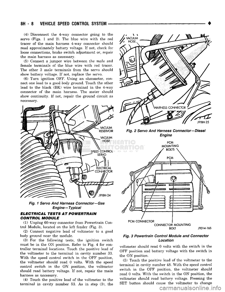
Fig.
1 Servo And Harness Connector—Gas
Engine—Typical
ELECTRICAL TESTS AT POWERTRAIN CONTROL MODULE
(1) Unplug 60-way connector from Powertrain Con
trol Module, located on the left fender (Fig. 3).
(2) Connect negative lead of voltmeter to a good
body ground near the module. (3) For the following tests, the ignition switch
must be in the ON position. Refer to Fig. 4 for con
troller terminal locations. Touch the positive lead of
the voltmeter to the terminal in cavity number 33.
With the speed control switch in the OFF position,
the voltmeter should read 0 volts. With the speed
control switch in the ON position, the voltmeter should read battery voltage. If not, repair the main
harness as necessary.
(4) Touch the positive lead of the voltmeter to the
terminal in cavity number 53. As in step (3), the J918H-25
Fig. 2 Servo And Harness Connector—Diesel Engine PCM
MOUNTING
BOLTS
PCM CONNECTOR CONNECTOR MOUNTING BOLT
J9314-165
Fig.
3 Powertrain Control
Module
and
Connector
Location
voltmeter should read 0 volts with the switch in the OFF position and battery voltage with the switch in
the ON position. (5) Touch the positive lead of the voltmeter to the
terminal in cavity number 48. With the speed control switch in the OFF position, the voltmeter should
read 0 volts. With the switch in the ON position, the voltmeter should read battery voltage. Pressing the SET button should cause the voltmeter to change
Page 428 of 1502
•
TURN SIGNALS
AND
HAZARD WARNING FLASHER
8J - 1
CONTENTS
page page
GENERAL
INFORMATION
1
MULTIFUNCTION SWITCH TESTING MULTIFUNCTION SWITCH SERVICE PROCEDURES
2
PROCEDURES
3
GENERAL
INFORMATION
TURN SIGNALS
DESCRIPTION With
the
ignition
key ON and the
multi-function
lever
in its UP or
DOWN position, current flows
through
the:
• turn signal flasher canister • Turn/Hazard switch
• turn indicator lamp
• front
and
rear bulbs. The selected turn signal indicator with front
and
rear turn signal bulbs will flash.
DIAGNOSIS High generator output voltage
can
burn
out
lamps rapidly. (1) Remove
and
inspect fuse
in
cavity
#9 of
fuse
block. Replace
if
necessary.
The
fuse block
is
behind
the lower instrument panel cover under steering wheel. (2) Turn
key to
ACCY. There should
be
battery
voltage
at the
fuse side
of the
turn signal flasher (bottom terminal).
If
not,
repair open circuit
in
wir
ing between fuse
and
flasher.
(3) Replace Turn Flasher with
2
lamp
12
volt rated
flasher that
is
know
to be
good.
The
lamps should
flash. If
not,
replace with original flasher
and
go to
next step.
(4) Measure voltage
at the
Turn/Hazard switch
connector cavity
#17.
Meter should read battery volt
age.
If
OK,
replace Turn/Hazard switch assembly.
If
not, repair open circuit
in
wiring between flasher
and Turn/Hazard switch connector.
HAZARD WARNING SYSTEM
DESCRIPTION
With
the
hazard switch
OUT,
current flows
through
the
• hazard flasher canister
• hazard switch
•
two
front turn signal bulbs
•
two
rear turn signal bulbs
• both indicator bulbs.
All
of the
turn lamps
and
both indicators will
flash.
DIAGNOSIS Hazard switch
in
ON.
The
park
and
stop lamps
should light.
If
not
replace
the 20
amp
fuse
in
fuse
block cavity
#13.
(1) Measure voltage
at
the
fuse side
of
the
flasher
(side terminal). Meter should read battery voltage.
If
not, repair open circuit
in
wiring
to
fuse. (2) Replace Hazard flasher with known good
flasher. Lamps should flash.
If
not, replace with orig
inal flasher
and go
to
next step.
(3) Measure voltage
at the
Turn/Hazard switch
connector cavity #13. Meter should read battery volt
age.
If
not,
repair open circuit
in
wiring
to
hazard
flasher.
TURN
SIGNAL AND HAZARD
WARNING
FLASHER
LOCATION
The turn signal
and
hazard warning flasher
are
both located
on the
fuse block (Fig.
1). The
fuse block is
on the
lower instrument panel cover under
the
steering column.
TURN SIGNALS AND HAZARD WARNING
FLASHER
Page 460 of 1502

•
POWER DOOR LOCKS
8P - 1
POWER DOOR LOCKS
CONTENTS
SERVICE
PROCEDURES
page
..
2
TEST PROCEDURES
page
..
1
equipped,
can be
by operating
the
GENERAL
INFORMATION
Both doors, when electrically
locked
or
unlocked electrically switch
on a
door panel. Both doors
can be
locked
or
unlocked mechanically
with
the
locking knob regardless
of
electrical locking and unlocking actuation.
TEST
PROCEDURES
The right
and
left front door
on all
vehicles
can be
locked
or
unlocked mechanically from
the
outside
with
the key or
electrically
as
described above.
The
left door
can
also
be
unlocked
by
actuation
of
the
in
side remote door handle.
FUSE
TEST
Locate
the
fuse
in
fuse cavity number
6 on the
fuse
block.
If
fuse
is
blown, replace
it. If
fuse blows again refer
to
Switch Test
and
Voltage Test procedures
to
find
the
short circuit.
SWITCH TEST
For switch testing, remove
the
switch from
its
mounting location. Using
an
ohmmeter, refer
to
(Fig. 1)
to
determine
if
continuity
is
correct
in the
Lock
and Unlock switch positions.
If
these results
are not
obtained, replace
the
switch. ®
3 SWITCH
POSITION
CONTINUITY
BOWEIN
OFF PINS
1 & 4
PINS
2 & 5
LOCK PINS
2 & 3
PINS
1 & 4
UNLOCK
PINS
3 &4
PINS
2 &5
PIN IDENTIFICATION
PIN SIDE
OF
SWITCH
Fig.
1
Door Lock
Switch
Continuity
VOLTAGE TEST
The following wiring test sequence determines
whether
or not
voltage
is
continuous through
the
body harness
to
switch. After removing switch from trim panel
for
testing
purposes, carefully separate multiple terminal block
on wiring harness from switch body. Connect
one
lead
of
test light
to
black wire terminal
and
touch other test light lead
to red
wire terminal.
If
the test
light comes
on, the
wiring circuit between
the
bat
tery
and
switch
is
functional.
If
light does
not
come
on, check
20 amp
fuse
or for a
broken wire.
ELECTRIC MOTOR TEST
Make certain battery
is in
normal condition before
circuits
are
tested. To determine which motor
is
defective, check each
individual door switch
for
lock
and
unlock
or
discon
nect
the
motors,
one at a
time, then operate
the
door lock switch.
In the
event that none
of the
motors
work,
the
problem may
be
caused
by a
shorted motor. Disconnecting
the
defective motor will allow
the
other
to
work. To test
an
individual door lock motor, disconnect
the wire connector
at the
motor. Apply
12
volts across
the
motor terminals
to
check
its
operation
in
one direction. Reverse
the
polarity
to
check
the
oper ation
in the
other direction.
If the
motor works,
check
the
wire harness
for
broken wires
or bad
con
nections.
If
the motor does
not
work, replace
it.
Should
the
motor malfunction
be the
result
of
bro
ken wiring
or an
internal open circuit,
it
should have no effect
on the
operation
of
the other motor.
Page 462 of 1502
•
POWER
WINDOWS
8S - 1
POWER WINDOWS
CONTENTS
page
SERVICE
PROCEDURES
3
GENERAL
INFORMATION
Power window motors are of the permanent mag
net type. A positive and negative battery connection
to either of the two motor terminals will cause the motor to rotate in one direction. Reversing current
through these same two connections will cause the motor to rotate in the opposite direction. Both motors are grounded through the master
switch by a black wire attached to a ground stud.
The stud is located on the back of the instrument
panel, on the right side of the steering column. It is necessary that the window be free to slide up
page
TEST
PROCEDURES
....................... 1
and down in the glass channels or tubes and tracks.
If the window is not free to move up and down, the
window motor will not be able to move the glass.
To determine if the glass is free, disconnect the
electric window regulator lift arm sliders from the
glass lift channels. Slide the window up and down by
hand.
A less positive method is to shake the glass in the
door, (with glass positioned between the up and down
stop positions). If the glass will move slightly from
side to side, front to rear, and up and down, the win
dow is probably not bound tight in the tracks.
TEST
PROCEDURES
SWITCH
VOLTAGE TEST
The following wiring test sequence determines
whether or not voltage is continuous through the
body harness to switch. (1) Remove power window/lock switch by inserting
a standard blade screwdriver into notch on forward
end of switch housing. Push screwdriver to depress
locking tab. Pull bezel out and forward to remove
from door panel. (2) Carefully separate multiple terminal block on
wiring harness from switch body. (3) Connect one lead of test light to black (BK)
wire terminal. Touch other test light lead to tan (TN)
wire terminal. If test light comes on, the wiring cir cuit between the battery and switch is functional. If
light does not come on, check 30 amp circuit breaker,
or for a broken wire or poor ground.
CIRCUIT
BREAKER
TEST
Locate the circuit breaker in fuse cavity number 12
on fuse block. Pull out slightly but be sure that cir
cuit breaker terminals still contact terminals in fuse
block. Connect ground wire of voltmeter to a good ground. With probe of voltmeter positive wire, check both terminals of circuit breaker for battery voltage.
If only one terminal checks at battery voltage, circuit
breaker is defective and must be replaced. If neither
terminal shows battery voltage, check for open or shorted circuit to circuit breaker.
SWITCH TEST
For switch testing, remove the switch from its
mounting location. Using an ohmmeter, refer to Figs. 1 and 2 to determine if continuity is correct in the
UP and DOWN switch positions. If continuity is cor
rect perform window lift motor test.
WINDOW
MOTOR TEST
(1) Connect positive lead (from a test battery) to
either of the two motor terminals. (2) Connect negative lead (from test battery) to re
maining motor terminal. (3) The motor should now rotate in one direction to
either move window up or down. (a) If window happens to already be in full UP
position and motor is connected to rotate in UP di rection, no movement will be observed.
Page 472 of 1502
-
CHIME/BUZZER WARNING SYSTEMS
8U - 1
CHIME/BUZZER
WARNING SYSTEMS
CONTENTS
page
DIAGNOSIS
GENERAL
INFORMATION
page
1
KEY-IN SWITCH REPLACEMENT
3
1
OPERATION
1
GENERAL
INFORMATION
The buzzer module is located to the right of the
steering column (Fig. 1). The buzzer sounds an audi
ble warning tone in any of the following conditions: • Vehicle lights are ON when the driver's door is
opened.
• The key is in the ignition and the driver's door is
open. • The ignition is switched ON and the driver's seat
belt is not buckled. Buzzer will quit after 4 to 8 sec
onds.
In addition to the buzzer, a seat belt light in
dicator turns on as a reminder to fasten seat belt.
BUZZER
MODULE
INTERMITTENT
WIPE MODULE
Fig, 1 Buzzer Module Location
OPERATION
Battery voltage for module operation is supplied to
two pins. Battery voltage is present at pin 7 at all
times (Figs. 2 and 3). Pin 1 receives voltage when
the ignition switch is turned ON.
SEA T BELT WARNING To sound the seat belt warning, the module needs:
• battery voltage at the ignition switch input (Pin 1)
• a ground at the seat belt switch.
• a ground at Pin 3 to activate the timer. This occurs when the seat belt switch is closed be
cause the driver's seat belt is not buckled. The "fas
ten belt" light will also turn on along with the
warning sound. KEY IN IGNITION
To sound the "key in ignition" alarm, the module
needs:
• the ignition key warning switch must be closed
• the driver's door jamb switch must be closed. These conditions ground pin 6 of the module. These
switches are closed when the driver's door is open
and the key is in the ignition.
LIGHTS ON To sound the "lights on" warning, the module
needs:
• the headlamp switch must be closed
*> the driver's door jamb switch must be closed. These conditions ground pin 6 of the module. These
switches are closed when the driver's door is open
and the headlamp switch is on.
DIAGNOSIS
If the buzzer unit does not operate as described,
check the two fuses for pins 1 and 7 (Figs. 2, 3 and 4) and replace as required. If the fuses are not defec
tive,
perform the following tests to determine if the
problem is in the module or in the wiring. Using a flat blade screwdriver, release the locking plastic clip
while carefully pulling out the module. Plug in a known good module and check its operation. If the
problem is not corrected by replacing the module, re move the module and continue as follows:
VOLTAGE TESTS Ignition in run, measure between the following
pins and vehicle ground.
• Measure voltage at buzzer module connector pin 1.
Meter should read battery voltage. If not, repair open
to ignition switch.
Turn ignition off and remove key from igni
tion.
• Measure voltage at buzzer module connector pin 7.
Meter should read battery voltage. If not, repair open
to fuse. Battery voltage is present at Pin 7 at all
times regardless of key position.
Page 478 of 1502
•
WIRING
DIAGRAMS
8W - 3 fer to a components name in the index if you are
unclear as to what a system may be called.
Diagram pages are arranged starting with the bat
tery and fuses. Then working into charging, starting, and ignition systems. After this they start at the
front of the vehicle and work to rear of the vehicle.
The diagrams end with connector identification
pages.
COMPONENT
IDENTIFICATION
To find a components actual location on the vehicle
refer to the wiring and components section index. This section shows the wire harness routing and the compo
nents location in the vehicle. When using this section
refer to the wiring diagrams for the general location of
the component. Then use the component identification index to locate the proper figure number.
SPLICE
LOCATIONS
Splices are indicated in the wiring diagrams by a
diamond with splice circuit code within it (Fig. 5 ex ample 1). If there is more than one splice per circuit
splice code a small box will be connected to the dia
mond with the splice number in it (Fig. 5 example 2). To locate a splice in the wire harness determine
the splice number from the wiring diagrams, then re
fer to the splice location index. This section shows
the general location of the splice in the harness.
EXAMPLE
1
EXAMPLE
2 918W-18
Fig.
5 Wiring
Splice
Examples
CONNECTORS
The connectors shown in the diagram are viewed from
the terminal end unless otherwise specified. For view ing bulkhead and engine controller connectors refer to
the back of the wiring diagrams. This area shows major connectors for pin and cavity identification.
TROUBLESHOOTING
WIRING
PROBLEMS
When troubleshooting wiring problems there are
six steps which can aid in the procedure. The steps
are listed and explained below. (1) Verify the problem.
(2) Verify any related symptoms. Perform opera
tional checks on components in the same circuit as the problem area. Refer to the wiring diagram fuse
application chart for circuit information. (3) Analyze the symptoms. Use the wiring dia
grams to determine what the circuit is doing, where
the problem most likely is occurring and where the diagnosis will continue. (4) Isolate the problem area. (5) Repair the problem.
(6) Verify proper operation. For this step check for
proper operation of all items on the circuit repaired. Refer to the wiring diagram fuse application chart.
FUSIBLE
LINKS
Vehicle wiring harnesses are equipped with fusible
links.
For protection against harness damage in the
event of a short. Fusible links are color coded as to
wire gauge size. Refer to the fusible link chart for color and gauge identification (Fig. 6).
Wire and
Gauge
Color
Code
Color
12 Ga.
BK
Black
14 Ga.
RD
Red
16 Ga.
DB
Dark
Blue
18 Ga.
GY
Gray
20 Ga.
OR
Orange
22 Ga.
WT
White
918W-19
Fig.
6 Fusible
Link
Chart
HARNESS
REPAIR
FUSIBLE
LINK
REPLACEMENT
CAUTION:
Do not replace blown fusible
links
with
a
standard
wire.
Only
use fusible type
wire
with
hyp-
alon
insulation or
damage
to the electrical
system
could
occur.
Also
make
sure
correct
gauge
of
wir
ing
is
used.
Refer to the wiring
diagrams
for proper
gauge
and
color.
When a fusible link blows it is important to find
out what the problem is. They are placed in the elec
trical system for protection against shorts to ground
that can be caused by a component or various wiring
failures. Do not just replace the fusible link to correct the problem.
When diagnosing a faulty fusible link it is impor
tant to check the wire carefully. In some instances
the link may be blown and it will not show through the insulation, the wire should be checked over its
entire length for internal breaks.
(1) Disconnect battery negative cable.
(2) Cut out the blown portion of the fusible link.
(3) Strip 1 inch of insulation from each end of the
existing fusible link.
(4) Place a piece of heat shrink tubing over one
side of the fusible link. Make sure the tubing will be
long enough to cover and seal the entire repair area.
(5) Cut a replacement piece of fusible link approx
imately two inches longer than the piece removed. (6) Remove one inch of insulation from each end of
the replacement fusible link.
Page 607 of 1502
9
- 2
ENGINES
rial surrounds each mounting hole. Excess material
can easily be wiped off. Components should be
torqued in place within 15 minutes. The use of a lo cating dowel is recommended during assembly to pre
vent smearing the material off location.
ENGINE PERFORMANCE
To provide best vehicle performance and lowest ve
hicle emissions, it is most important that the tune-up
be done accurately. Use the specifications listed on
the Vehicle Emission Control Information label found on the engine compartment hood.
(1) Test cranking amperage draw (refer to Group
8B,
Battery/Starter/Generator Service for the proper
procedures).
(2) Tighten the intake manifold bolts (refer to
Group 11, Exhaust System and Intake Manifold for
the proper specifications). (3) Perform cylinder compression test:
(a) Check engine oil level and add oil, if neces
sary.
(b) Drive the vehicle until engine reaches normal
operating temperature. (c) Select a route free from traffic and other
forms of congestion, observe all traffic laws and
briskly accelerate through the gears several times. The higher engine speed may help clean out valve seat deposits which can prevent accurate compres
sion readings.
CAUTION:
DO NOT
overspeed
the
engine.
(d) Remove all spark plugs from engine. As
spark plugs are being removed, check electrodes for
abnormal firing indicators - fouled, hot, oily, etc.
Record cylinder number of spark plug for future
reference.
(e) Disconnect coil wire from distributor and se
cure to good ground to prevent a spark from start
ing a fire.
(f) Be sure throttle blades are fully open during
the compression check. (g) Insert compression gage adaptor into the
No.l spark plug hole. Crank engine until maxi
mum pressure is reached on gauge. Record this
pressure as No.l cylinder pressure.
(h) Repeat Step 3g for all remaining cylinders.
(i) Compression should not be less than 689 kPa
(100 psi) and not vary more than 172 kPa (25 psi)
from cylinder to cylinder.
(j) If cylinder(s) have abnormally low compres
sion pressures, repeat steps 3a through 3h. (k) If the same cylinder(s) repeat an abnormally
low reading, it could indicate the existence of a
problem in the cylinder.
The recommended compression pressures are
to be used only as a guide to diagnosing engine
problems. An engine should NOT be disassem bled to determine the cause of low compression
unless some malfunction is present. (4) Clean or replace spark plugs as necessary. Ad
just gap (refer to Group 8D, Ignition System for gap adjustment and torque).
(5) Test resistance of spark plug cables (refer to
Group 8D, Ignition System.
(6) Inspect the primary wire. Test coil output volt
age,
primary and secondary resistance. Replace parts as necessary (refer to Group 8D, Ignition System and
make necessary adjustment).
(7) Set ignition timing to specifications (refer to
Specification Label on engine compartment hood).
(8) Perform a combustion analysis.
(9) Test fuel pump for pressure and vacuum (refer
to Group 14, Fuel System for the proper specifica
tions).
(10) Inspect air filter element (refer to Group 0,
Lubrication and Maintenance for the proper proce
dure).
(11) Inspect crankcase ventilation system (refer to
Group 0, Lubrication and Maintenance for the proper
procedure).
(12) For emission controls refer to Group 25, Emis
sion Controls System for service procedures.
(13) Inspect and adjust accessory belt drives (refer
to Group 7, Cooling System for the proper adjust
ments).
(14) Road test vehicle as a final test.
H0NIN6
CYLINDER
BORES
Before honing, stuff plenty of clean shop towels un
der the bores and over the crankshaft to keep abra sive materials from entering the crankshaft area.
(1) Used carefully, the Cylinder Bore Sizing Hone
C-823 equipped with 220 grit stones, is the best tool
for this job. In addition to deglazing, it will reduce
taper and out-of-round as well as removing light scuffing, scoring or scratches. Usually a few strokes
will clean up a bore and maintain the required lim
its.
CAUTION:
DO NOT use rigid type
hones
to remove
cylinder
wall
glaze.
(2) Deglazing of the cylinder walls may be done if
the cylinder bore is straight and round. Use a cylin
der surfacing hone, Honing Tool C-3501, equipped
with 280 grit stones (C-3501-3810). 20-60 strokes, de
pending on the bore condition, will be sufficient to
provide a satisfactory surface. Using honing oil C-3501-3880 or a light honing oil available from ma
jor oil distributors.
CAUTION:
DO NOT use engine or
transmission
oil, mineral
spirits
or
kerosene.