power steering DODGE TRUCK 1993 Service Owner's Guide
[x] Cancel search | Manufacturer: DODGE, Model Year: 1993, Model line: TRUCK, Model: DODGE TRUCK 1993Pages: 1502, PDF Size: 80.97 MB
Page 626 of 1502
•
3.9L
ENGINE
9 - 21 (25) Lower the vehicle.
(26) On automatic transmission vehicles, discon
nect the engine from the torque converter drive
plate. On manual transmission vehicles, move engine forward until drive pinion shaft clears the clutch
disc.
Remove engine from engine compartment. (27) Install engine assembly on engine repair
stand.
INSTALLATION (1) Remove engine from the repair stand and posi
tion in the engine compartment.
(2) Install engine support fixture.
(3) Raise and support the vehicle on a hoist.
(4)
AUTOMATIC TRANSMISSION: (a) Position the torque converter and drive plate.
Install torque converter drive plate bolts. Tighten
the bolts to 31 Nnn (270 in. lbs.) torque.
(b) Install the engine front mounts.
(c) Install bell housing bolts. Tighten the bolts to
41 N-m (30 ft. lbs.) torque.
(d) Remove C-clamp.
(e) Install the inspection plate.
(5) MANUAL TRANSMISSION: (a) Position the drive pinion shaft to the clutch
disc.
(b) Connect the clutch release mechanism and
install the transmission to clutch bolts. Tighten the
bolts to 68 N-m (50 ft. lbs.) torque.
(c) Install the engine front mounts.
(6) Remove transmission support.
(7) Install exhaust pipe to manifold.
(8) Lower the vehicle.
(9) Remove engine lifting fixture.
(10) Install the generator (refer to Group 8B, Bat
tery/Starter/Generator Service). (11) Install starter motor (refer to Group 8B, Bat
tery/Starter/Generator Service). (12) Connect power steering hoses, if equipped.
(13) Connect air conditioning hoses.
(14) Evacuate and charge the air conditioning sys
tem, if equipped (refer to Group 24, Heater and Air Conditioning for service procedures). (15) Using a new gasket, install MPI throttle body.
Tighten the throttle body bolts to 23 N-m (200 in. lbs.) torque. (16) Connect the accelerator linkage.
(17) Connect the starter wires. (18) Connect the oil pressure wire.
(19) Install the distributor cap and wiring.
(20) Connect the vacuum lines.
(21) Connect the fuel lines.
(22) Install the radiator (refer to Group 7, Cooling
System). Connect the radiator hoses and heater
hoses.
(23) Install fan shroud in position. (24) Fill cooling system (refer to Group 7, Cooling
System for the proper procedures). (25) Install the air cleaner.
(26) Install the battery.
(27) Warm engine and adjust.
(28) Install hood and line up with the scribe
marks. (29) Road test vehicle.
CYLINDER
HEAD COVER
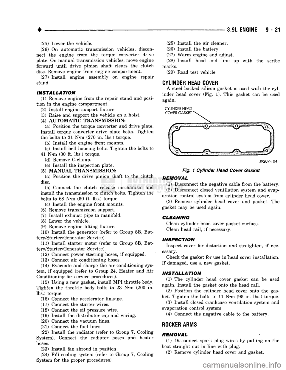
A steel backed silicon gasket is used with the cyl
inder head cover (Fig. 1). This gasket can be used again.
CYLINDER HEAD COVER GASKET
J9209-104
Fig.
1 Cylinder Head
Cover
Gasket
REMOVAL (1) Disconnect the negative cable from the battery.
(2) Disconnect closed ventilation system and evap
oration control system from cylinder head cover. (3) Remove cylinder head cover and gasket. The
gasket may be used again.
CLEANING Clean cylinder head cover gasket surface. Clean head rail, if necessary.
INSPECTION Inspect cover for distortion and straighten, if nec
essary. Check the gasket for use in "head cover installation.
If damaged, use a new gasket.
INSTALLATION (1) The cylinder head cover gasket can be used
again. Install the gasket onto the head rail.
(2) Position the cylinder head cover onto the gas
ket. Tighten the bolts to 11 N-m (95 in. lbs.) torque. (3) Install closed crankcase ventilation system and
evaporation control system.
(4) Connect the negative cable to the battery.
ROCKER
ARMS
REMOVAL (1) Disconnect spark plug wires by pulling on the
boot straight out in line with plug.
(2) Remove cylinder head cover and gasket.
Page 634 of 1502
•
3.9L
ENGINE
I - 21
VIBRATION
DAMPER
REMOVAL
(1) Disconnect the negative cable from the battery,
(2) Remove fan shroud retainer bolts and set
shroud back over engine.
(3) Remove the cooling system fan.
(4) Remove the serpentine belt (refer to Group 7,
Cooling System).
(5) Remove the vibration damper pulley.
(6) Remove vibration damper bolt and washer from
end of crankshaft.
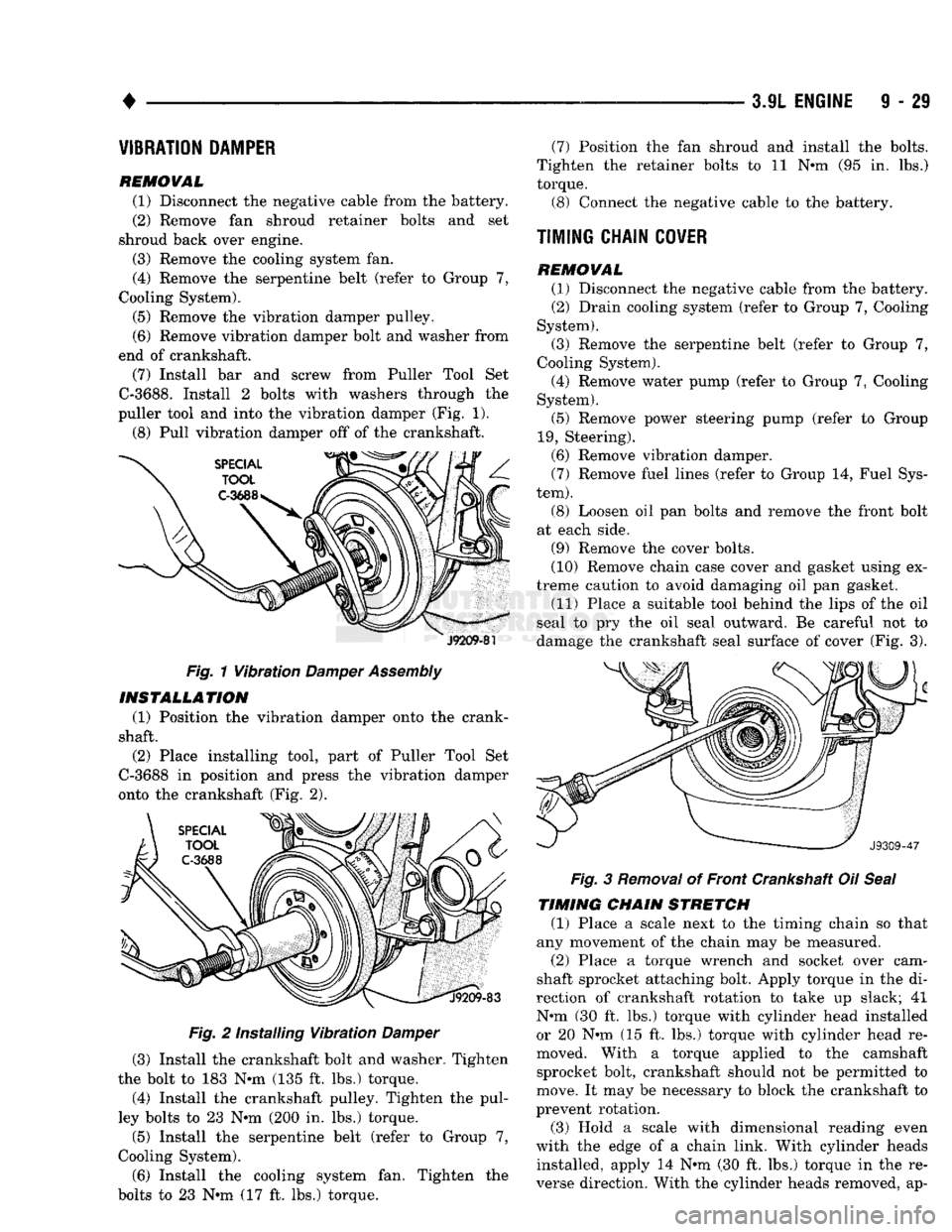
(7) Install bar and screw from Puller Tool Set
C-3688.
Install 2 bolts with washers through the
puller tool and into the vibration damper (Fig. 1).
(8) Pull vibration damper off of the crankshaft.
J9209-81
Fig. 1 Vibration
Damper
Assembly INSTALLATION
(1) Position the vibration damper onto the crank
shaft.
(2) Place installing tool, part of Puller Tool Set
C-3688 in position and press the vibration damper
onto the crankshaft (Fig. 2).
Fig. 2 Installing Vibration Damper
(3) Install the crankshaft bolt and washer. Tighten
the bolt to 183 N*m (135 ft. lbs.) torque.
(4) Install the crankshaft pulley. Tighten the pul
ley bolts to 23 N*m (200 in. lbs.) torque.
(5) Install the serpentine belt (refer to Group 7,
Cooling System).
(6) Install the cooling system fan. Tighten the
bolts to 23 N*m (17 ft. lbs.) torque. (7) Position the fan shroud and install the bolts.
Tighten the retainer bolts to 11 N*m (95 in. lbs.)
torque.
(3)
Connect the negative cable to the battery.
TIMING CHAIN
COVER
REMOVAL (1)
Disconnect the negative cable from the battery.
(2)
Drain cooling system (refer to Group 7, Cooling
System).
(3)
Remove the serpentine belt (refer to Group 7,
Cooling System).
(4)
Remove water pump (refer to Group 7, Cooling
System).
(5)
Remove power steering pump (refer to Group
19,
Steering).
(6)
Remove vibration damper. (7) Remove fuel lines (refer to Group 14, Fuel Sys
tem).
(8) Loosen oil pan bolts and remove the front bolt
at each side.
(9)
Remove the cover bolts.
(10)
Remove chain case cover and gasket using ex
treme caution to avoid damaging oil pan gasket.
(11)
Place a suitable tool behind the lips of the oil
seal to pry the oil seal outward. Be careful not to
damage the crankshaft seal surface of cover (Fig. 3). Fig. 3 Removal of Front Crankshaft Oil Seal
TIMING CHAIN STRETCH
(1) Place a scale next to the timing chain so that
any movement of the chain may be measured.
(2)
Place a torque wrench and socket over cam
shaft sprocket attaching bolt. Apply torque in the di
rection of crankshaft rotation to take up slack; 41
N#m (30 ft. lbs.) torque with cylinder head installed or 20 N»m (15 ft. lbs.) torque with cylinder head re
moved. With a torque applied to the camshaft sprocket bolt, crankshaft should not be permitted to
move. It may be necessary to block the crankshaft to
prevent rotation.
(3)
Hold a scale with dimensional reading even
with the edge of a chain link. With cylinder heads installed, apply 14 N*m (30 ft. lbs.) torque in the re
verse direction. With the cylinder heads removed, ap-
Page 636 of 1502
•
3.9L
ENGINE
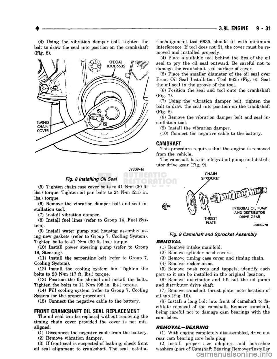
9 - 31 (4) Using the vibration damper bolt, tighten the
bolt to draw the seal into position on the crankshaft (Fig. 8).
J9309-46
Fig.
8 installing Oil
Seal
(5) Tighten chain case cover bolts to 41 N-m (30 ft.
lbs.) torque. Tighten oil pan bolts to 24 N*m (215 in.
lbs.) torque.
(6) Remove the vibration damper bolt and seal in
stallation tool.
(7) Install vibration damper. (8) Instajl fuel lines (refer to Group 14, Fuel Sys
tem).
(9) Install water pump and housing assembly us
ing new gaskets (refer to Group 7, Cooling System).
Tighten bolts to 41 N-m (30 ft. lbs.) torque. (10) Install power steering pump (refer to Group
19,
Steering). (11) Install the serpentine belt (refer to Group 7,
Cooling System). (12) Install the cooling system fan. Tighten the
bolts to 23 N-m (17 ft. lbs.) torque. (13) Position the fan shroud and install the bolts.
Tighten the bolts to 11 N-m (95 in. lbs.) torque. (14) Fill cooling system (refer to Group 7, Cooling
System for the proper procedure). (15) Connect the negative cable to the battery.
FRONT
CRANKSHAFT
OIL
SEAL REPLACEMENT
The oil seal can be replaced without removing the
timing chain cover provided the cover is not mis aligned. (1) Disconnect the negative cable from the battery.
(2) Remove vibration damper.
(3) If front seal is suspected of leaking, check front
oil seal alignment to crankshaft. The seal installa tion/alignment tool 6635, should fit with minimum
interference. If tool does not fit, the cover must be re
moved and installed properly.
(4)
Place a suitable tool behind the lips of the oil
seal to pry the oil seal outward. Be careful not to
damage the crankshaft seal surface of cover.
(5) Place the smaller diameter of the oil seal over
Front Oil Seal Installation Tool 6635 (Fig. 6). Seat
the oil seal in the groove of the tool.
(6) Position the seal and tool onto the crankshaft
(Fig. 7). (7) Using the vibration damper bolt, tighten the
bolt to draw the seal into position on the crankshaft (Fig. 8).
(8) Remove the vibration damper bolt and seal in
stallation tool. (9) Install the vibration damper.
(10) Connect the negative cable to the battery.
CAMSHAFT
This procedure requires that the engine is removed
from the vehicle.. The camshaft has an integral oil pump and distrib
utor drive gear (Fig. 9).
CHAIN
SPROCKET
Fig.
9 Camshaft and
Sprocket
Assembly
REMOVAL
(1) Remove intake manifold.
(2) Remove cylinder head covers. (3) Remove timing case cover and timing chain.
(4) Remove rocker arms.
(5) Remove push rods and tappets; identify each
part so it can be installed in the original location. (6) Remove distributor and lift out the oil pump
and distributor drive shaft.
(7) Remove camshaft thrust plate; note location of
oil tab (Fig. 10).
(8) Install a long bolt into front of camshaft to fa
cilitate removal of the camshaft. Remove camshaft,
being careful not to damage cam bearings with the cam lobes.
RE
MO
VAL-BEA RING
(1) With engine completely disassembled, drive out
rear cam bearing core hole plug.
(2) Install proper size adapters and horseshoe
washers (part of Camshaft Bearing Remover/Installer
Page 655 of 1502
TRANSFER
CASE
TRANSFER
CASE
ENGINE
REAR
SUPPORT PLATE
EXTENSION
ASSEMBLY
TRANSMISSION
SUPPORT
SPACER
SPACER
UPPER
INSULATOR
INSULATOR
MOUNTING
PLATE
LOWER
INSULATOR
fT^RAIL
J9109-244
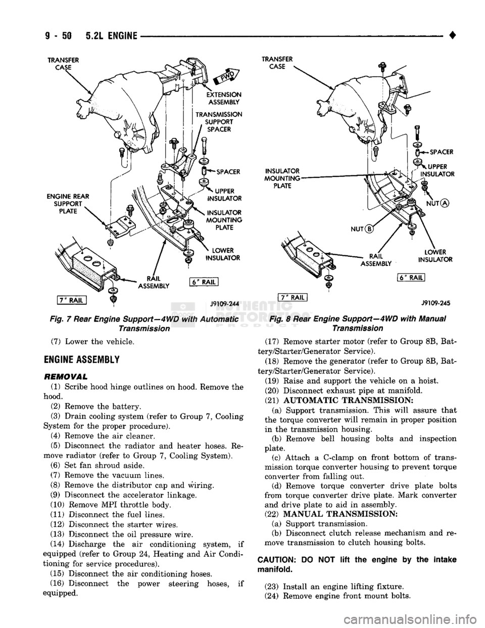
Fig,
7 Rear Engine Support—4WD
with
Automatic
Transmission
(7)
Lower the vehicle.
ENGINE
ASSEMBLY
REMOVAL
(1) Scribe hood hinge outlines on hood. Remove the
hood. (2) Remove the battery.
(3) Drain cooling system (refer to Group 7, Cooling
System for the proper procedure). (4) Remove the air cleaner.
(5) Disconnect the radiator and heater hoses. Re
move radiator (refer to Group 7, Cooling System). (6) Set fan shroud aside.
(7)
Remove the vacuum lines.
(8) Remove the distributor cap and wiring.
(9) Disconnect the accelerator linkage.
(10) Remove MPI throttle body.
(11) Disconnect the fuel lines.
(12) Disconnect the starter wires.
(13) Disconnect the oil pressure wire.
(14) Discharge the air conditioning system, if
equipped (refer to Group 24, Heating and Air Condi
tioning for service procedures).
(15) Disconnect the air conditioning hoses.
(16) Disconnect the power steering hoses, if
equipped.
INSULATOR
MOUNTING
PLATE
SPACER
UPPER
L\ f
INSULATOR
NUT®
RAIL
ASSEMBLY
LOWER
INSULATOR
l6ff
RAIL
I
J9109-245
Fig.
8 Rear
Engine
Support—4WD
with
Manual
Transmission
(17) Remove starter motor (refer to Group 8B, Bat
tery/Starter/Generator Service).
(18) Remove the generator (refer to Group 8B, Bat
tery/Starter/Generator Service).
(19) Raise and support the vehicle on a hoist.
(20) Disconnect exhaust pipe at manifold.
(21)
AUTOMATIC TRANSMISSION: (a) Support transmission. This will assure that
the torque converter will remain in proper position in the transmission housing. (b) Remove bell housing bolts and inspection
plate. (c) Attach a C-clamp on front bottom of trans
mission torque converter housing to prevent torque
converter from falling out. (d) Remove torque converter drive plate bolts
from torque converter drive plate. Mark converter and drive plate to aid in assembly.
(22)
MANUAL TRANSMISSION; (a) Support transmission.
(b) Disconnect clutch release mechanism and re
move transmission to clutch housing bolts.
CAUTION:
manifold.
DO
NOT lift the
engine
by the
intake
(23) Install an engine lifting fixture.
(24) Remove engine front mount bolts.
Page 656 of 1502
•
5.2L
ENGINE
9 - 51 (25) Lower the vehicle.
(26) On automatic transmission vehicles, discon
nect the engine from the torque converter drive
plate. On manual transmission vehicles, move engine forward until drive pinion shaft clears the clutch
disc.
Remove engine from engine compartment.
(27) Install engine assembly on engine repair
stand.
INSTALLATION
(1) Remove engine from the repair stand and posi
tion in the engine compartment.
(2) Install an engine support fixture.
(3) Raise and support the vehicle on a hoist.
(4) AUTOMATIC TRANSMISSION: (a) Position the torque converter and drive plate.
Install torque converter drive plate bolts. Tighten
the bolts to 31 N-m (270 in. lbs.) torque.
(b) Install the engine front mounts.
(c) Install bell housing bolts. Tighten the bolts to
41 N-m (30 ft. lbs.) torque.
(d) Remove C-clamp.
(e) Install the inspection plate.
(5) MANUAL TRANSMISSION: (a) Position the drive pinion shaft to the clutch
disc.
(b) Connect the clutch release mechanism and
install the transmission to clutch bolts. Tighten the
bolts to 68 N-m (50 ft. lbs.) torque.
(c) Install the engine front mounts.
(6) Remove transmission support.
(7) Install exhaust pipe to manifold. (8) Lower the vehicle.
(9) Remove engine lifting fixture. (10) Install the generator (refer to Group 8B, Bat
tery/Starter/ Generator Service). (11) Install the starter motor (refer to Group 8B,
Battery/Starter/Generator Service). (12) Connect power steering hoses, if so equipped.
(13) Connect air conditioning hoses.
(14) Evacuate and charge the air conditioning sys
tem, if equipped (refer to Group 24, Heater and Air Conditioning for service procedures).
(15) Using a new gasket, install MPI throttle body.
Tighten the throttle body bolts to 23 N-m (200 in. lbs.) torque. (16) Connect the accelerator linkage.
(17) Connect the starter wires.
(18) Connect the oil pressure wire. (19) Install the distributor cap and wiring.
(20) Connect the vacuum lines.
(21) Connect the fuel lines,
(22) Install the radiator (refer to Group 7, Cooling
System). Connect the radiator hoses and heater
hoses.
(23) Install fan shroud in position.
(24) Fill cooling system (refer to Group 7, Cooling
System for the proper procedure). (25) Install the air cleaner.
(26) Install the battery. (27) Warm engine and adjust.
(28) Install hood and line up with the scribe
marks. (29) Road test vehicle.
CYLIiiER
HEAD
COVER
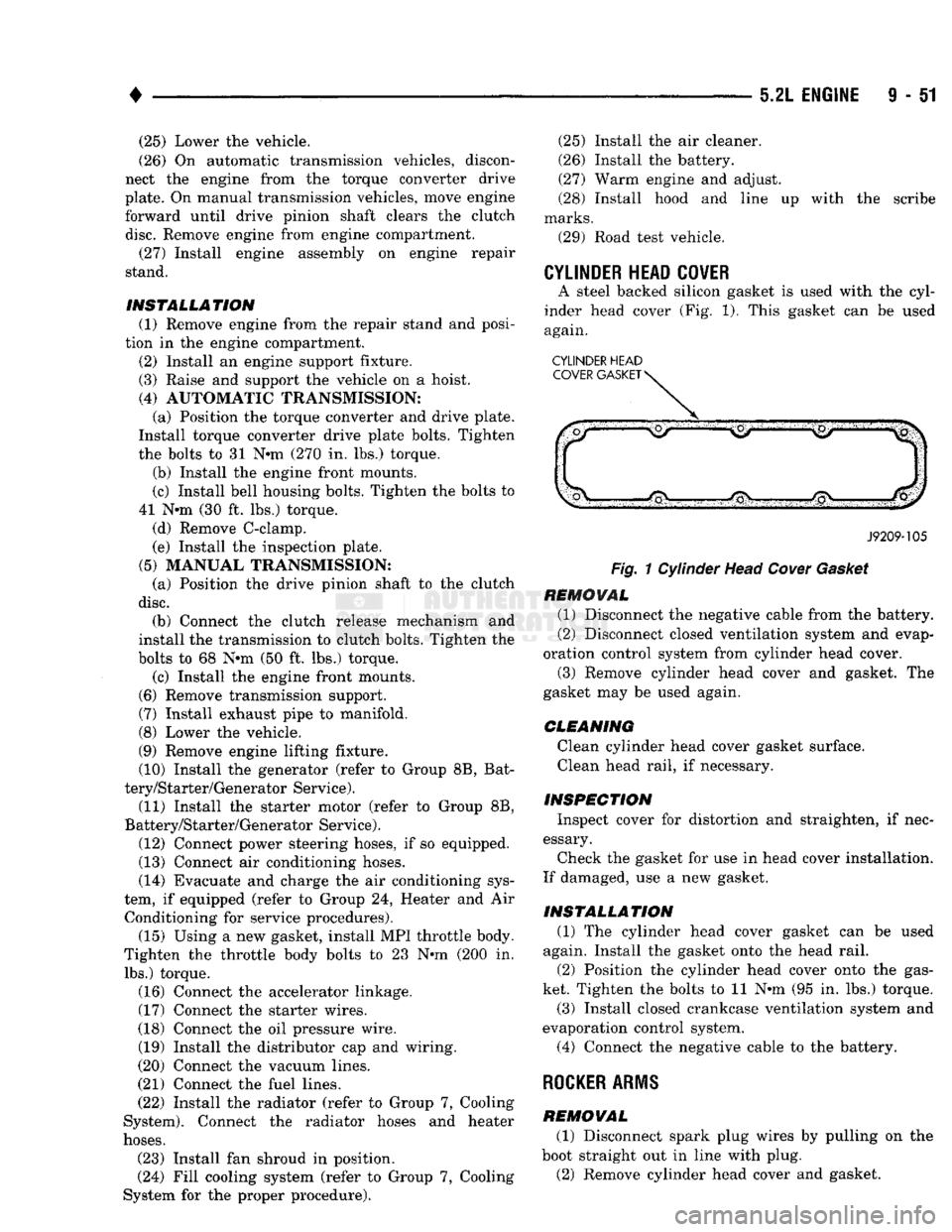
A steel backed silicon gasket is used with the cyl
inder head cover (Fig. 1). This gasket can be used
again.
CYLINDER HEAD
J9209-105
Fig.
1 Cylinder Head
Cover
Gasket
REMOVAL
(1) Disconnect the negative cable from the battery.
(2) Disconnect closed ventilation system and evap
oration control system from cylinder head cover.
(3) Remove cylinder head cover and gasket. The
gasket may be used again.
CLEANING
Clean cylinder head cover gasket surface. Clean head rail, if necessary.
INSPECTION
Inspect cover for distortion and straighten, if nec
essary.
Check the gasket for use in head cover installation.
If damaged, use a new gasket.
INSTALLATION
(1) The cylinder head cover gasket can be used
again. Install the gasket onto the head rail.
(2) Position the cylinder head cover onto the gas
ket. Tighten the bolts to 11 N-m (95 in. lbs.) torque.
(3) Install closed crankcase ventilation system and
evaporation control system.
(4) Connect the negative cable to the battery.
ROCKER ARMS
REMOVAL
(1) Disconnect spark plug wires by pulling on the
boot straight out in line with plug. (2) Remove cylinder head cover and gasket.
Page 664 of 1502
•
5.2L
ENGINE
9 - 59
INSTALLATION
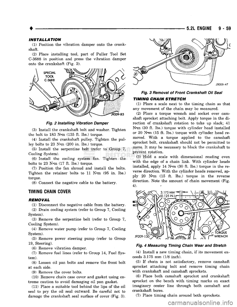
(1) Position the vibration damper onto the crank
shaft. (2) Place installing tool, part of Puller Tool Set
C-3688 in position and press the vibration damper
onto the crankshaft (Fig. 2).
Fig.
2 Installing
Vibration
Damper
(3) Install the crankshaft bolt and washer. Tighten
the bolt to 183 N*m (135 ft. lbs.) torque.
(4) Install the crankshaft pulley. Tighten the pul
ley bolts to 23 Nin (200 in. lbs.) torque.
(5) Install the serpentine belt (refer to Group 7,
Cooling System).
(6) Install the cooling system fan. Tighten the
bolts to 23 N*m (17 ft. lbs.) torque.
(7) Position the fan shroud and install the bolts.
Tighten the retainer bolts to 11 N»m (95 in. lbs.)
torque.
(8) Connect the negative cable to the battery.
TIMING
CHAIN
COVER
REMOVAL (1) Disconnect the negative cable from the battery.
(2) Drain cooling system (refer to Group 7, Cooling
System).
(3) Remove the serpentine belt (refer to Group 7,
Cooling System).
(4) Remove water pump (refer to Group 7, Cooling
System).
(5) Remove power steering pump (refer to Group
19,
Steering). (6) Remove vibration damper.
(7) Remove fuel lines (refer to Group 14, Fuel Sys
tem).
(8) Loosen oil pan bolts and remove the front bolt
at each side.
(9) Remove the cover bolts.
(10) Remove chain case cover and gasket using ex
treme caution to avoid damaging oil pan gasket.
(11) Place a suitable tool behind the lips of the oil
seal to pry the oil seal outward. Be careful not to
damage the crankshaft seal surface of cover (Fig. 3).
Fig.
3
Removal
of Front Crankshaft Oil
Seal
TIMING
CHAIN
STRETCH
(1) Place a scale next to the timing chain so that
any movement of the chain may be measured.
(2) Place a torque wrench and socket over cam
shaft sprocket attaching bolt. Apply torque in the di
rection of crankshaft rotation to take up slack; 41
N»m (30 ft. lbs.) torque with cylinder head installed
or 20 N»m (15 ft. lbs.) torque with cylinder head re
moved. With a torque applied to the camshaft sprocket bolt, crankshaft should not be permitted to
move. It may be necessary to block the crankshaft to
prevent rotation.
(3) Hold a scale with dimensional reading even
with the edge of a chain link. With cylinder heads installed, apply 14 Nnn (30 ft. lbs.) torque in the re
verse direction. With the cylinder heads removed, ap
ply 20 N»m (15 ft. lbs.) torque in the reverse direction. Note the amount of chain movement (Fig.
4).
Fig.
4
Measuring
Timing
Chain
Wear and Stretch
(4) Install a new timing chain, if its movement ex
ceeds 3.175 mm (1/8 inch). (5) If chain is not satisfactory, remove camshaft
sprocket attaching bolt and remove timing chain
with crankshaft and camshaft sprockets.
(6) Place both camshaft sprocket and crankshaft
sprocket on the bench with timing marks on exact
imaginary center line through both camshaft and
crankshaft bores.
(7) Place timing chain around both sprockets.
Page 665 of 1502
9
- 60 5.2L
ENGINE
(8) Turn crankshaft and camshaft to line up with
keyway location in crankshaft sprocket and in cam shaft sprocket.
(9) Lift sprockets and chain (keep sprockets tight
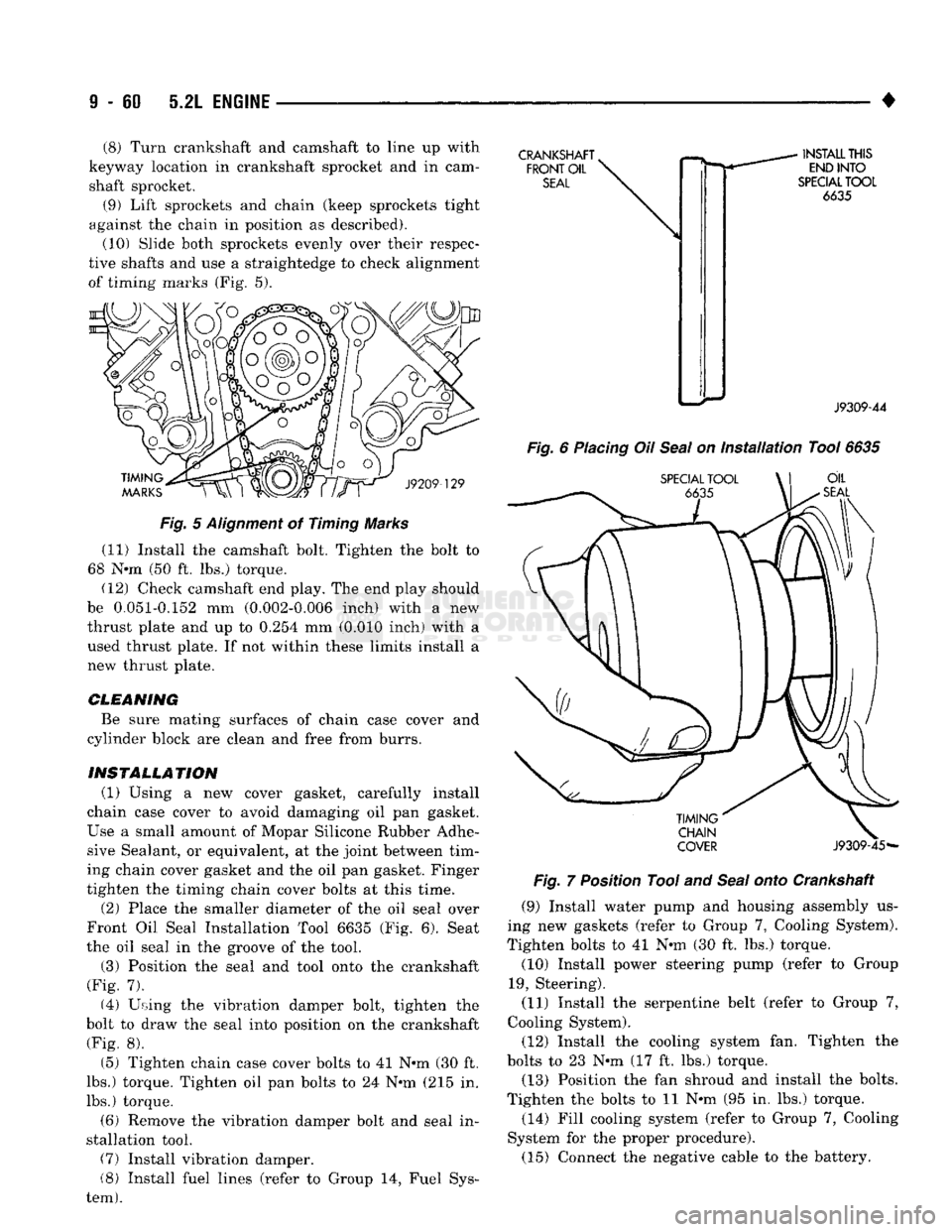
against the chain in position as described). (10) Slide both sprockets evenly over their respec
tive shafts and use a straightedge to check alignment
of timing marks (Fig. 5).
TIMING
MARKS
J9209-129
Fig.
5
Alignment
of Timing Marks (11) Install the camshaft bolt. Tighten the bolt to
68 Nnn (50 ft. lbs.) torque. (12) Check camshaft end play. The end play should
be 0.051-0.152 mm (0.002-0.006 inch) with a new
thrust plate and up to 0.254 mm (0.010 inch) with a used thrust plate. If not within these limits install a
new thrust plate.
CLEANING Be sure mating surfaces of chain case cover and
cylinder block are clean and free from burrs.
INSTALLATION (1) Using a new cover gasket, carefully install
chain case cover to avoid damaging oil pan gasket.
Use a small amount of Mopar Silicone Rubber Adhe sive Sealant, or equivalent, at the joint between tim
ing chain cover gasket and the oil pan gasket. Finger
tighten the timing chain cover bolts at this time.
(2) Place the smaller diameter of the oil seal over
Front Oil Seal Installation Tool 6635 (Fig. 6). Seat
the oil seal in the groove of the tool.
(3) Position the seal and tool onto the crankshaft
(Fig. 7). (4) Using the vibration damper bolt, tighten the
bolt to draw the seal into position on the crankshaft (Fig. 8).
(5) Tighten chain case cover bolts to 41 Nnn (30 ft.
lbs.) torque. Tighten oil pan bolts to 24 Nnn (215 in.
lbs.) torque.
(6) Remove the vibration damper bolt and seal in
stallation tool. (7) Install vibration damper.
(8) Install fuel lines (refer to Group 14, Fuel Sys
tem).
CRANKSHAFT
k
FRONT
OIL
SEAL
INSTALL
THIS
END
INTO
SPECIAL
TOOL
6635
J9309-44
Fig.
6
Placing
Oil
Seal
on
Installation
Tool
6635
SPECIAL
TOOL
\ | OIL
SEAL
TIMING
CHAIN
COVER
J9309-45*-
Fig.
7 Position Tool and
Seal
onto Crankshaft
(9) Install water pump and housing assembly us
ing new gaskets (refer to Group 7, Cooling System).
Tighten bolts to 41 Nnn (30 ft. lbs.) torque.
(10) Install power steering pump (refer to Group
19,
Steering).
(11) Install the serpentine belt (refer to Group 7,
Cooling System).
(12) Install the cooling system fan. Tighten the
bolts to 23 Nnn (17 ft. lbs.) torque. (13) Position the fan shroud and install the bolts.
Tighten the bolts to 11 Nnn (95 in. lbs.) torque.
(14) Fill cooling system (refer to Group 7, Cooling
System for the proper procedure).
(15) Connect the negative cable to the battery.
Page 685 of 1502
9
- 80 5.9L
ENGINE
•
TRANSFER
CASE
TRANSFER
CASE
ENGINE REAR
SUPPORT
PLATE
INSULATOR
MOUNTING
PLATE
LOWER
INSULATOR
\7"
RAIL
1
J9109-244
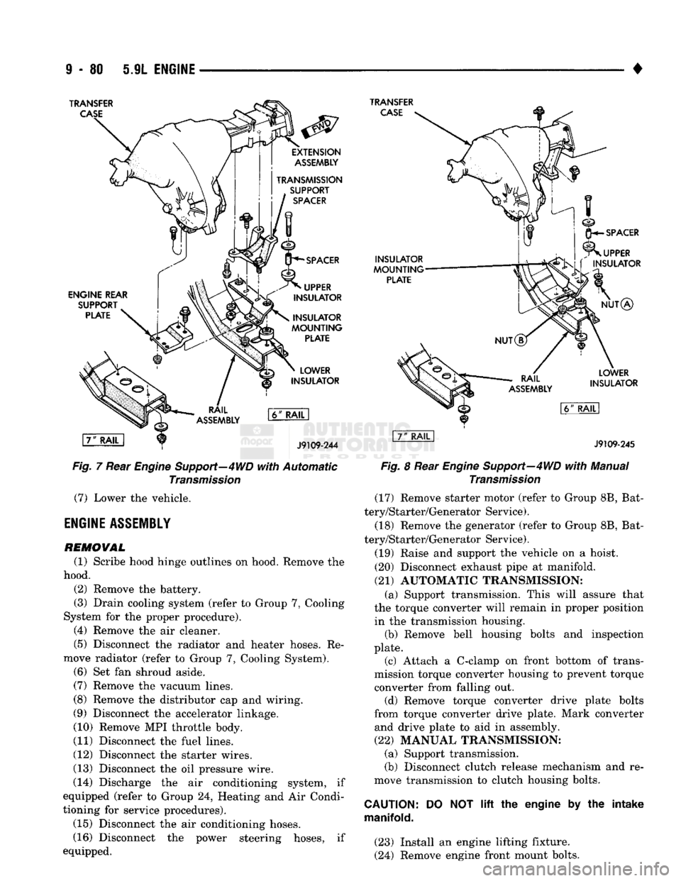
Fig.
7 Rear
Engine
Support—4WD
with
Automatic
Transmission
(7) Lower the vehicle.
ENGINE
ASSEMBLY
REMOVAL
(1) Scribe hood hinge outlines on hood. Remove the
hood. (2) Remove the battery.
(3) Drain cooling system (refer to Group 7, Cooling
System for the proper procedure). (4) Remove the air cleaner.
(5) Disconnect the radiator and heater hoses. Re
move radiator (refer to Group 7, Cooling System). (6) Set fan shroud aside.
(7) Remove the vacuum lines.
(8) Remove the distributor cap and wiring.
(9) Disconnect the accelerator linkage.
(10) Remove MPI throttle body.
(11) Disconnect the fuel lines.
(12) Disconnect the starter wires.
(13) Disconnect the oil pressure wire.
(14) Discharge the air conditioning system, if
equipped (refer to Group 24, Heating and Air Condi
tioning for service procedures).
(15) Disconnect the air conditioning hoses.
(16) Disconnect the power steering hoses, if
equipped.
INSULATOR
MOUNTING
PLATE
SPACER
UPPER
INSULATOR
NUT®
LOWER
INSULATOR
J9109-245
Fig.
8 Rear
Engine
Support—4WD
with
Manual
Transmission
(17) Remove starter motor (refer to Group 8B, Bat
tery/Starter/Generator Service).
(18) Remove the generator (refer to Group 8B, Bat
tery/Starter/Generator Service).
(19) Raise and support the vehicle on a hoist.
(20) Disconnect exhaust pipe at manifold.
(21) AUTOMATIC TRANSMISSION: (a) Support transmission. This will assure that
the torque converter will remain in proper position in the transmission housing. (b) Remove bell housing bolts and inspection
plate. (c) Attach a C-clamp on front bottom of trans
mission torque converter housing to prevent torque converter from falling out. (d) Remove torque converter drive plate bolts
from torque converter drive plate. Mark converter and drive plate to aid in assembly.
(22) MANUAL TRANSMISSION; (a) Support transmission.
(b) Disconnect clutch release mechanism and re
move transmission to clutch housing bolts.
CAUTION:
manifold.
DO
NOT
lift
the engine by the intake
(23) Install an engine lifting fixture.
(24) Remove engine front mount bolts.
Page 686 of 1502
•
5.9L ENGINE
9-81 (25) Lower the vehicle.
(26) On automatic transmission vehicles, discon
nect the engine from the torque converter drive
plate. On manual transmission vehicles, move engine forward until drive pinion shaft clears the clutch
disc.
Remove engine from engine compartment.
(27) Install engine assembly on engine repair
stand.
INSTALLATION (1) Remove engine from the repair stand and posi
tion in the engine compartment.
(2) Install an engine support fixture.
(3) Raise and support the vehicle on a hoist.
(4)
AUTOMATIC TRANSMISSION: (a) Position the torque converter and drive plate.
Install torque converter drive plate bolts. Tighten
the bolts to 31 Nnn (270 in. lbs.) torque.
(b) Install the engine front mounts.
(c) Install bell housing bolts. Tighten the bolts to
41 Nnn (30 ft. lbs.) torque.
(d) Remove C-clamp.
(e) Install the inspection plate.
(5)
MANUAL TRANSMISSION: (a) Position the drive pinion shaft to the clutch
disc.
(b) Connect the clutch release mechanism and
install the transmission to clutch bolts. Tighten the
bolts to 68 Nnn (50 ft. lbs.) torque.
(c) Install the engine front mounts.
(6) Remove transmission support.
(7) Install exhaust pipe to manifold. (8) Lower the vehicle.
(9) Remove engine lifting fixture.
(10) Install the generator (refer to Group 8B, Bat
tery/Starter/Generator Service). (11) Install the starter motor (refer to Group 8B,
Battery/Starter/Generator Service).
(12) Connect power steering hoses, if so equipped.
(13) Connect air conditioning hoses.
(14) Evacuate and charge the air conditioning sys
tem, if equipped (refer to Group 24, Heater and Air Conditioning for service procedures).
(15) Using a new gasket, install MPI throttle body.
Tighten the throttle body bolts to 23 Nnn (200 in. lbs.) torque.
(16) Connect the accelerator linkage. (17) Connect the starter wires.
(18) Connect the oil pressure wire.
(19) Install the distributor cap and wiring.
(20) Connect the vacuum lines.
(21) Connect the fuel lines.
(22) Install the radiator (refer to Group 7, Cooling
System). Connect the radiator hoses and heater
hoses.
(23) Install fan shroud in position.
(24) Fill cooling system (refer to Group 7, Cooling
System for the proper procedure). (25) Install the air cleaner.
(26) Install the battery.
(27) Warm engine and adjust.
(28) Install hood and line up with the scribe
marks. (29) Road test vehicle.
CYLINDER HEAD COVER
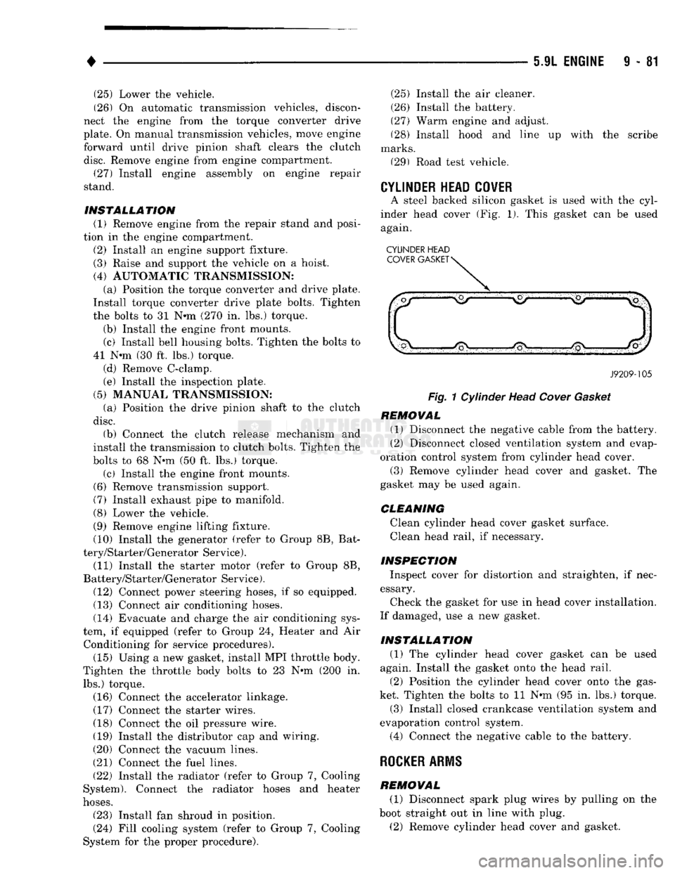
A steel backed silicon gasket is used with the cyl
inder head cover (Fig. 1). This gasket can be used
again.
CYLINDER HEAD
J9209-105
Fig.
1 Cylinder Head
Cover
Gasket
REMOVAL (1) Disconnect the negative cable from the battery.
(2) Disconnect closed ventilation system and evap
oration control system from cylinder head cover.
(3) Remove cylinder head cover and gasket. The
gasket may be used again.
CLEANING
Clean cylinder head cover gasket surface.
Clean head rail, if necessary.
INSPECTION Inspect cover for distortion and straighten, if nec
essary.
Check the gasket for use in head cover installation.
If damaged, use a new gasket.
INSTALLATION (1) The cylinder head cover gasket can be used
again. Install the gasket onto the head rail.
(2) Position the cylinder head cover onto the gas
ket. Tighten the bolts to 11 Nnn (95 in. lbs.) torque. (3) Install closed crankcase ventilation system and
evaporation control system.
(4) Connect the negative cable to the battery.
ROCKER
ARMS
REMOVAL (1) Disconnect spark plug wires by pulling on the
boot straight out in line with plug.
(2) Remove cylinder head cover and gasket.
Page 694 of 1502
•
5.9L
ENGINE
9 - 89
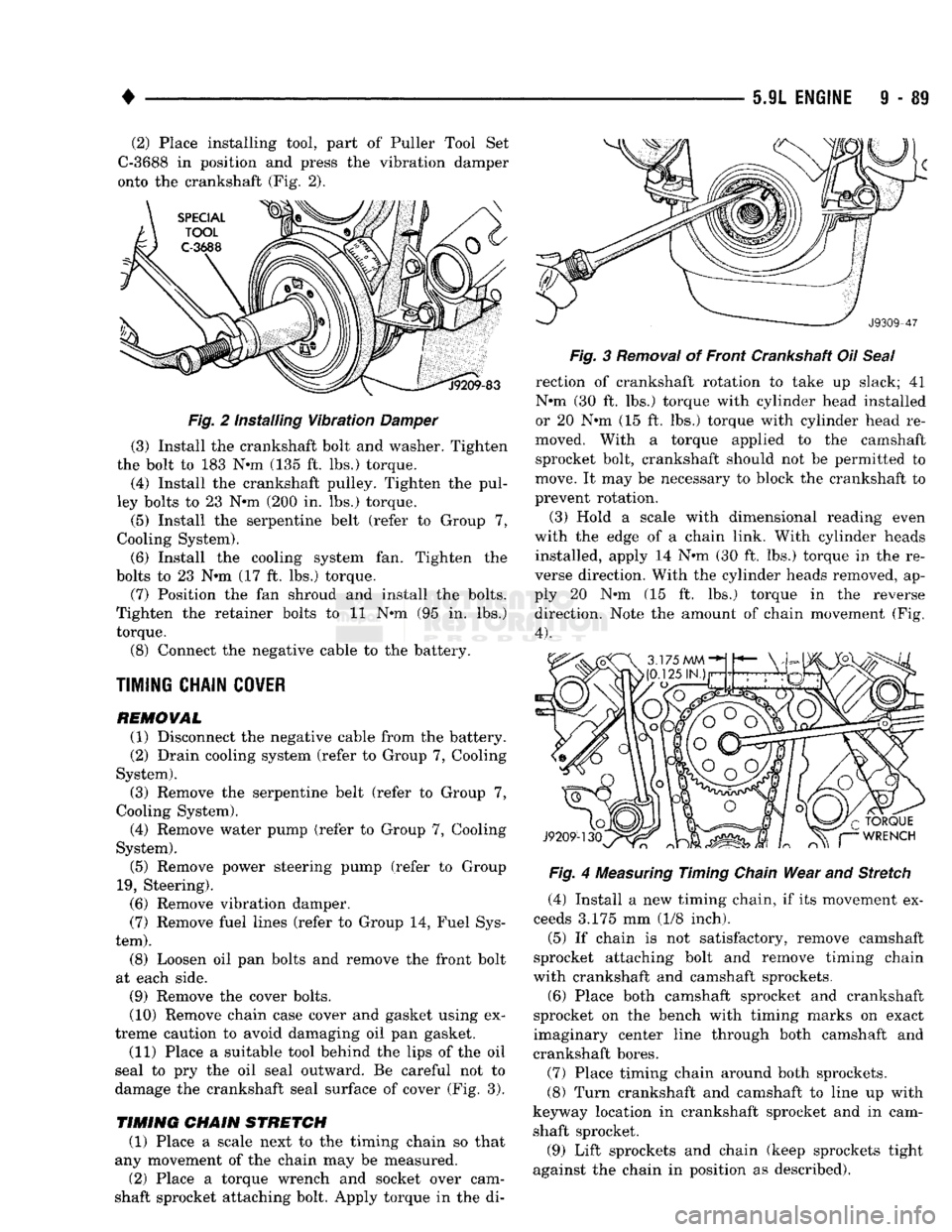
(2) Place installing tool, part of Puller Tool Set
C-3688 in position and press the vibration damper
onto the crankshaft (Fig. 2).
Fig. 2 Installing Vibration Damper (3) Install the crankshaft bolt and washer. Tighten
the bolt to 183 N-m (135 ft. lbs.) torque.
(4) Install the crankshaft pulley. Tighten the pul
ley bolts to 23 N-m (200 In. lbs.) torque.
(5) Install the serpentine belt (refer to Group 7,
Cooling System). (6) Install the cooling system fan. Tighten the
bolts to 23 N-m (17 ft. lbs.) torque.
(7) Position the fan shroud and install the bolts.
Tighten the retainer bolts to 11 N-m (95 in. lbs.)
torque.
(8) Connect the negative cable to the battery.
TIMING CHAIN COWER
REMOVAL
(1) Disconnect the negative cable from the battery.
(2) Drain cooling system (refer to Group 7, Cooling
System).
(3) Remove the serpentine belt (refer to Group 7,
Cooling System). (4) Remove water pump (refer to Group 7, Cooling
System).
(5) Remove power steering pump (refer to Group
19,
Steering). (6) Remove vibration damper.
(7) Remove fuel lines (refer to Group 14, Fuel Sys
tem).
(8) Loosen oil pan bolts and remove the front bolt
at each side. (9) Remove the cover bolts.
(10) Remove chain case cover and gasket using ex
treme caution to avoid damaging oil pan gasket.
(11) Place a suitable tool behind the lips of the oil
seal to pry the oil seal outward. Be careful not to
damage the crankshaft seal surface of cover (Fig. 3).
TIMING
CHAIN
STRETCH
(1) Place a scale next to the timing chain so that
any movement of the chain may be measured.
(2) Place a torque wrench and socket over cam
shaft sprocket attaching bolt. Apply torque in the di- Fig. 3 Removal of Front Crankshaft Oil Seal
rection of crankshaft rotation to take up slack; 41
N-m (30 ft, lbs.) torque with cylinder head installed
or 20 N-m (15 ft. lbs.) torque with cylinder head re
moved. With a torque applied to the camshaft sprocket bolt, crankshaft should not be permitted to
move. It may be necessary to block the crankshaft to
prevent rotation.
(3) Hold a scale with dimensional reading even
with the edge of a chain link. With cylinder heads installed, apply 14 N-m (30 ft. lbs.) torque In the re
verse direction. With the cylinder heads removed, ap
ply 20 N-m (15 ft. lbs.) torque In the reverse direction. Note the amount of chain movement (Fig.
4).
Fig. 4 Measuring Timing Chain Wear and Stretch
(4) Install a new timing chain, if its movement ex
ceeds 3.175 mm (1/8 inch). (5) If chain is not satisfactory, remove camshaft
sprocket attaching bolt and remove timing chain
with crankshaft and camshaft sprockets,
(6) Place both camshaft sprocket and crankshaft
sprocket on the bench with timing marks on exact
imaginary center line through both camshaft and
crankshaft bores.
(7) Place timing chain around both sprockets.
(8) Turn crankshaft and camshaft to line up with
keyway location in crankshaft sprocket and in cam
shaft sprocket.
(9) Lift sprockets and chain (keep sprockets tight
against the chain in position as described).