power steering DODGE TRUCK 1993 Service Workshop Manual
[x] Cancel search | Manufacturer: DODGE, Model Year: 1993, Model line: TRUCK, Model: DODGE TRUCK 1993Pages: 1502, PDF Size: 80.97 MB
Page 968 of 1502
•
STEERING
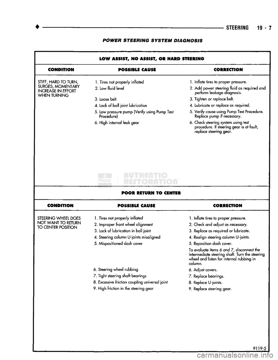
19 - 7 POWER STEERING SYSTEM DIAGNOSIS
LOW
ASSIST,
NO
ASSIST,
OR
HARD
STEERING
CONDITION
POSSIBLE CAUSE
CORRECTION
STIFF,
HARD
TO TURN,
SURGES,
MOMENTARY
INCREASE
IN
EFFORT
WHEN
TURNING
1.
Tires not properly inflated
2. Low
fluid level
3.
Loose belt
1.
Inflate tires to proper pressure.
2.
Add power steering fluid as required and perform leakage diagnosis.
3.
Tighten or replace belt.
4.
Lack of ball joint lubrication
4.
Lubricate or replace as required.
5.
Low pressure pump (Verify using Pump Test Procedure)
5.
Verify cause using Pump Test Procedure.
Replace pump if necessary.
6. High internal leak gear 6. Check steering system using test
procedure. If steering gear is at fault, replace steering gear.
POOR RETURN
TO
CENTER
CONDITION POSSIBLE CAUSE CORRECTION
STEERING
WHEEL
DOES
NOT WANT
TO
RETURN
TO CENTER POSITION
1.
Tires not properly inflated
2.
Improper front wheel alignment
3.
Lack of lubrication in ball joint
1.
Inflate tires to proper pressure.
2.
Check and adjust as necessary.
3.
Replace as required or lubricate.
4.
Steering column U-joints misaligned
4.
Realign steering column U-joints.
5.
Mispositioned dash cover
5.
Reposition dash cover.
To
evaluate items 6 and 7, disconnect the intermediate steering shaft. Turn the steering
wheel and listen for internal rubbing in column.
6. Steering wheel rubbing 6. Adjust covers.
7.
Tight steering shaft bearings
7.
Replace bearings.
8. Excessive friction coupling universal joint 8. Replace U-joints.
9. High friction in the steering gear 9. Replace steering gear.
91195
Page 969 of 1502
19
- 8
STEERING
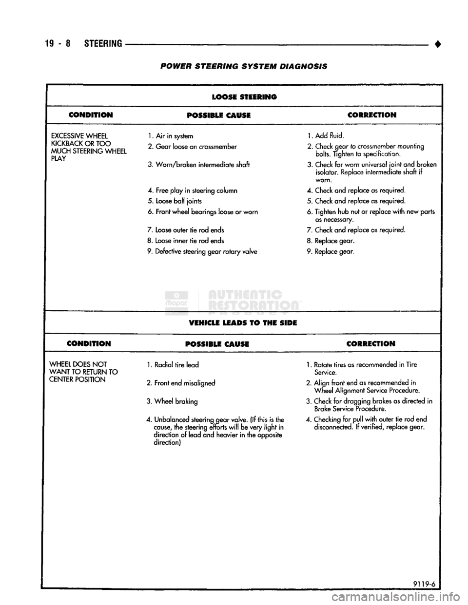
POWER
STEERING
SYSTEM
DIAGNOSIS
LOOSE
STEERING
CONDITION
POSSIBLE
CAUSE
CORRECTION
EXCESSIVE
WHEEL
KICKBACK
OR
TOO
MUCH
STEERING
WHEEL
PLAY
1.
Air in system
2.
Gear
loose
on
crossmember
3.
Worn/broken intermediate shaft
4.
Free
play in steering column
5.
Loose
ball
joints
6. Front wheel bearings
loose
or worn
7.
Loose
outer tie rod
ends
8.
Loose
inner
tie
rod
ends
9.
Defective steering gear
rotary
valve
1.
Add
fluid.
2.
Check
gear
to
crossmember
mounting bolts. Tighten
to
specification,
3.
Check
for worn universal
joint
ond
broken isolator.
Replace
intermediate shaft
if
worn.
4.
Check
and replace
as
required. 5.
Check
and replace
as
required.
6.
Tighten hub nut or replace
with
new parts
as
necessary.
7.
Check
and replace
as
required.
8.
Replace
gear.
9.
Replace
gear.
VEHICLE
LEADS
TO THE
SIDE
CONDITION
POSSIBLE
CAUSE
CORRECTION
WHEEL
DOES
NOT
WANT
TO
RETURN
TO
CENTER
POSITION
1. Radial
tire
lead
2. Front
end
misaligned
3.
Wheel braking
4.
Unbalanced
steering
gear
valve.
(If this is the
cause,
the steering
efforts
will
be very
light
in
direction
of
lead and heavier in the opposite
direction)
1.
Rotate
tires
as
recommended in Tire
Service.
2. Align
front
end
as
recommended
in
Wheel
Alignment
Service
Procedure.
3.
Check
for
dragging
brakes
as
directed
in
Brake
Service
Procedure.
4.
Checking
for
pull
with
outer
tie
rod end
disconnected.
If verified, replace gear.
9119-6
Page 970 of 1502
•
STEERING
19-9 POWER STEERING SYSTEM DIAGNOSIS
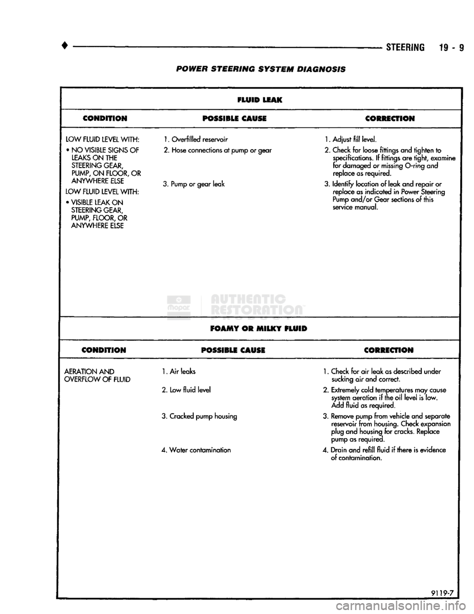
FLUID
LEAK
CONDITION POSSIBLE CAUSE
CORRECTION
LOW
FLUID LEVEL
WITH: •NO
VISIBLE
SIGNS
OF
LEAKS ON THE
STEERING GEAR,
PUMP,
ON
FLOOR,
OR
ANYWHERE ELSE
LOW FLUID LEVEL WITH: • VISIBLE LEAK ON STEERING GEAR, PUMP, FLOOR, OR
ANYWHERE ELSE
1.
Overfilled reservoir
2.
Hose connections at pump or gear
3.
Pump or gear leak
1.
Adjust fill level.
2.
Check for loose fittings and tighten to specifications. If fittings are tight, examine
for damaged or missing
O-ring
and replace as required.
3.
Identify location of leak and repair or replace as indicated in Power Steering
Pump and/or Gear sections of this
service manual.
FOAMY OR MILKY FLUID
CONDITION POSSIBLE CAUSE CORRECTION
AERATION AND
OVERFLOW OF FLUID
1.
Air leaks
2.
Low
fluid level
3.
Cracked pump housing
4.
Water contamination
1.
Check for air leak as described under
sucking air and correct.
2.
Extremely cold temperatures may cause system aeration if the oil level is low.
Add fluid as required.
3.
Remove pump from vehicle and separate reservoir from housing. Check expansion
plug and housing for
cracks.
Replace
pump as required.
4.
Drain and refill fluid if there is evidence of contamination.
9119-7
Page 972 of 1502
•
STEERING
19 - 11
POWER STEERING PUMP
INDEX
page
Power
Steering
Hose
11
Power
Steering Pump—Initial Operation
15
Pump
Pulley
15
Pump
Replacement—Diesel Engine
12
SERVICE
INFORMATION
The power steering pump internal components are
not serviced or adjusted. If a malfunction or an inter
nal fluid leak occurs, the complete unit must be re
placed.
POWER
STEERING HOSE
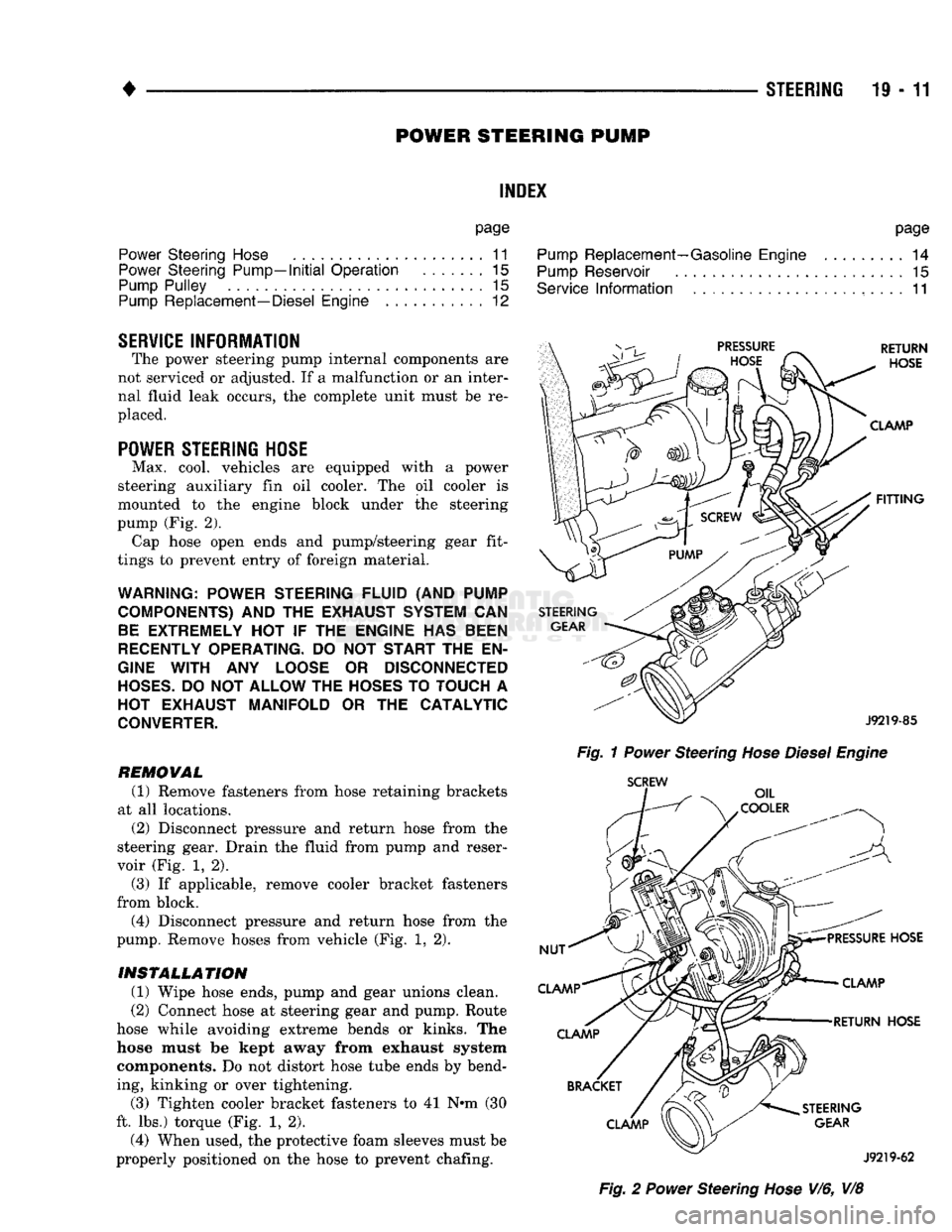
Max. cool, vehicles are equipped with a power
steering auxiliary fin oil cooler. The oil cooler is
mounted to the engine block under the steering
pump (Fig. 2). Cap hose open ends and pump/steering gear fit
tings to prevent entry of foreign material.
WARNING; POWER STEERING
FLUID
(AND
PUMP
COMPONENTS)
AND THE
EXHAUST SYSTEM
CAN
BE EXTREMELY
HOT IF THE
ENGINE
HAS
BEEN
RECENTLY OPERATING.
DO NOT
START
THE EN
GINE WITH
ANY
LOOSE
OR
DISCONNECTED
HOSES.
DO
NOT
ALLOW
THE
HOSES
TO
TOUCH
A
HOT EXHAUST
MANIFOLD
OR THE
CATALYTIC
CONVERTER.
REMOWAL (1) Remove fasteners from hose retaining brackets
at all locations. (2) Disconnect pressure and return hose from the
steering gear. Drain the fluid from pump and reser
voir (Fig. 1, 2).
(3) If applicable, remove cooler bracket fasteners
from block. (4) Disconnect pressure and return hose from the
pump. Remove hoses from vehicle (Fig. 1, 2).
INSTALLATION
(1) Wipe hose ends, pump and gear unions clean.
(2) Connect hose at steering gear and pump. Route
hose while avoiding extreme bends or kinks. The
hose must be kept away from exhaust system components. Do not distort hose tube ends by bend
ing, kinking or over tightening.
(3) Tighten cooler bracket fasteners to 41 N»m (30
ft. lbs.) torque (Fig. 1, 2). (4) When used, the protective foam sleeves must be
properly positioned on the hose to prevent chafing. page
Pump
Replacement—Gasoline Engine
......... 14
Pump
Reservoir
15
Service
Information
....................... 11
Fig.
1
Power
Steering
Hose Diesel Engine
SCREW
Fig.
2
Power
Steering
Hose
V/6, V/8
Page 973 of 1502
19
- 12
STEERING
• (5) Tighten fittings at pump and gear to 35 Nnn
(25 ft. lbs.) torque.
(6)
Install clamps on return hose on gear and
pump.
(7)
After installation, inspect and test for fluid
leaks.
PUMP REPLACEMENT—DIESEL ENGINE
REMOVAL
(1) Place a drain pan under the power steering
pump.
(2) Disconnect and cap the vacuum and steering
pump hoses.
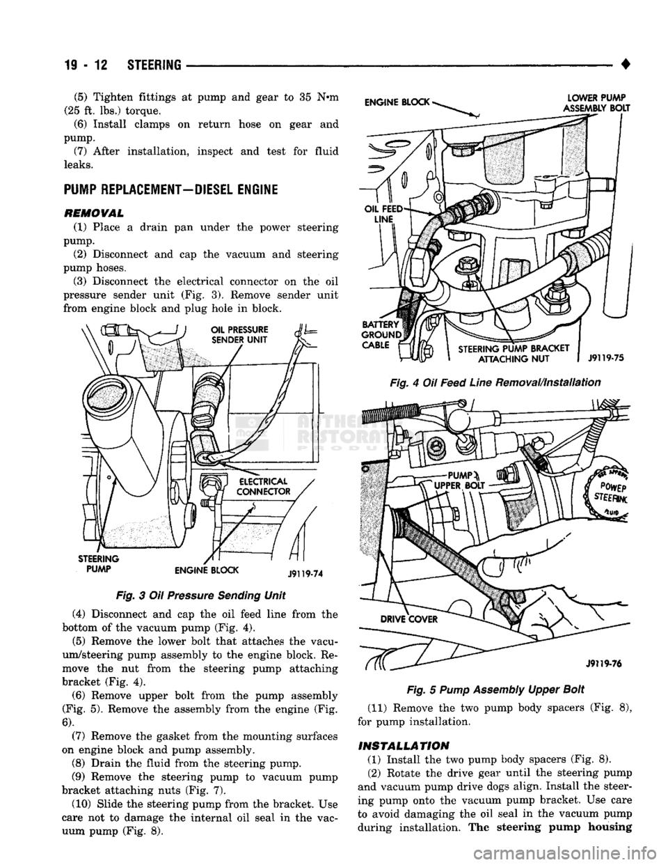
(3) Disconnect the electrical connector on the oil
pressure sender unit (Fig. 3). Remove sender unit
from engine block and plug hole in block.
PUMP ENGINE BLOCK Fig.
3 Oil
Pressure
Sending
Unit
(4) Disconnect and cap the oil feed line from the
bottom of the vacuum pump (Fig. 4). (5) Remove the lower bolt that attaches the vacu
um/steering pump assembly to the engine block. Re
move the nut from the steering pump attaching
bracket (Fig. 4).
(6)
Remove upper bolt from the pump assembly
(Fig. 5). Remove the assembly from the engine (Fig.
6).
(7) Remove the gasket from the mounting surfaces
on engine block and pump assembly.
(8) Drain the fluid from the steering pump.
(9) Remove the steering pump to vacuum pump
bracket attaching nuts (Fig. 7).
(10) Slide the steering pump from the bracket. Use
care not to damage the internal oil seal in the vac uum pump (Fig. 8).
Fig.
4 Oil
Feed
Line
Removal/Installation
Fig.
5
Pump
Assembly
Upper
Bolt
(11) Remove the two pump body spacers (Fig. 8),
for pump installation.
INSTALLATION (1) Install the two pump body spacers (Fig. 8).
(2) Rotate the drive gear until the steering pump
and vacuum pump drive dogs align. Install the steer
ing pump onto the vacuum pump bracket. Use care
to avoid damaging the oil seal in the vacuum pump during installation. The steering pump housing
Page 975 of 1502
19
- 14
STEERING
• (9) Install the fluid hoses to the power steering
pump, Tighten the pressure fitting at the pump to 30
N*m (22 ft. lbs.) torque.
(10) Install and clamp the hose on the vacuum
pump. (11) Fill the reservoir with power steering fluid
only. If necessary, refer to Pump Initial Operation
for detailed instructions.
(12) Start and run the engine. Check the operation
of the brakes, if necessary refer to Group 5, Brakes
for additional information.
PUMP REPLACEMENT—GASOLINE ENGINE
REMOVAL
WARNING:
DO NOT
REMOVE
THE
WATER PUMP COOLANT TUBE UNLESS
THE
COOLANT SYSTEM HAS BEEN DEPRESSUR1ZED
AND
DRAINED*
WARNING:
DO NOT
ATTEMPT
TO
REMOVE
THE
PUMP
WITHOUT
REMOVING
THE
BELT FIRST.
THE
AUTOMATIC TENSIONER
IS
UNDER
A
HIGH
SPRING
LOAD.
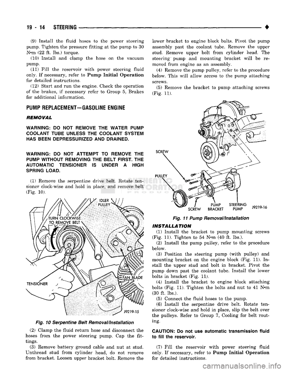
(1) Remove the serpentine drive belt. Rotate ten
sioner clock-wise and hold in place, and remove belt
(Fig. 10).
Fig.
10 Serpentine Belt Removal/Installation
(2) Clamp the fluid return hose and disconnect the
hoses from the power steering pump. Cap the fit
tings.
(3) Remove battery ground cable and nut at stud.
Unthread stud from cylinder head, do not remove
from bracket. Loosen upper bracket bolt. Remove the lower bracket to engine block bolts. Pivot the pump
assembly past the coolant tube. Remove the upper
stud. Remove upper bolt from cylinder head. The
steering pump and mounting bracket will be re
moved from engine as an assembly.
(4) Remove the pump pulley, refer to the procedure
below. This will allow access to the pump attaching screws.
(5)
Remove the bracket to pump attaching screws
(Fig. 11).
Fig.
11
Pump
Removal/Installation
INSTALLATION
(1) Install the bracket to pump mounting screws
(Fig. 11). Tighten to 54 N-m (40 ft. lbs.). (2) Install the pump pulley, refer to the procedure
below.
(3) Position the steering pump (with pulley) and
mounting bracket on the engine block (Fig. 11). In stall the upper stud and bolt in bracket. Pivot the
pump down past the coolant tube. Install the lower
bolts in bracket (Fig. 11). (4) Install the bracket to engine block attaching
bolts (Fig. 11). Tighten the bolts and nut to 41 N*m (30 ft. lbs.).
(5) Connect the fluid hoses to the pump. (6) Install the serpentine drive belt. Rotate ten
sioner clock-wise and hold in place, slip the belt over
the pulleys. Refer to Group 7, Cooling for belt rout ing.
CAUTION:
Do not use
automatic
transmission
fluid
to
fill the
reservoir.
(7) Fill the reservoir with power steering fluid
only. If necessary, refer to Pump Initial Operation
for detailed instructions.
Page 976 of 1502
#
_ ,
Fig.
12 Pulley
Removal
(Typical)
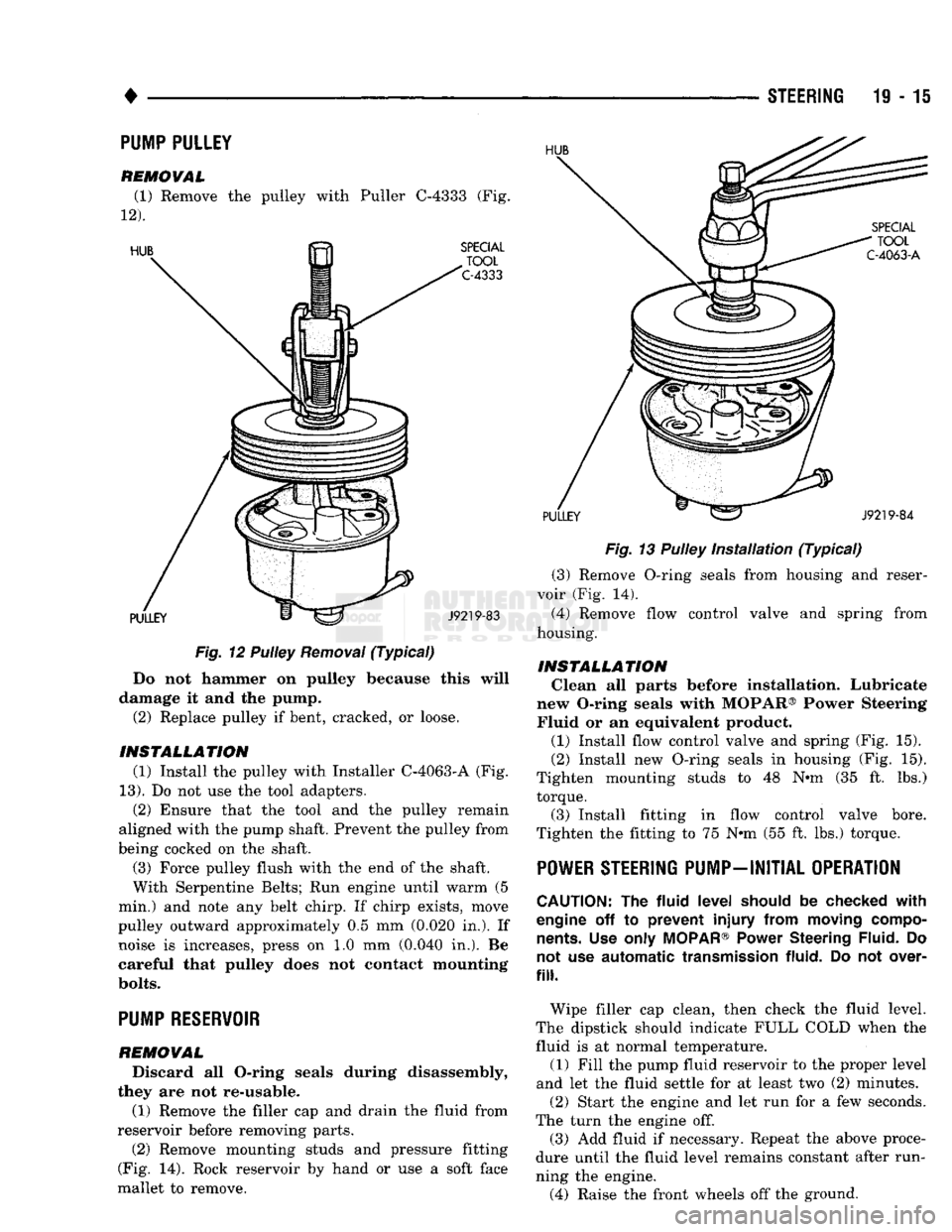
Do not hammer on pulley because this will
damage it and the pump. (2) Replace pulley if bent, cracked, or loose.
INSTALLATION (1) Install the pulley with Installer C-4063-A (Fig.
13).
Do not use the tool adapters. (2) Ensure that the tool and the pulley remain
aligned with the pump shaft. Prevent the pulley from
being cocked on the shaft.
(3) Force pulley flush with the end of the shaft.
With Serpentine Belts; Run engine until warm (5
min.) and note any belt chirp. If chirp exists, move
pulley outward approximately 0.5 mm (0.020 in.). If noise is increases, press on 1.0 mm (0.040 in.). Be
careful that pulley does not contact mounting
bolts.
PUMP RESERVOIR
REMOVAL
Discard all O-ring seals during disassembly,
they are not re-usable.
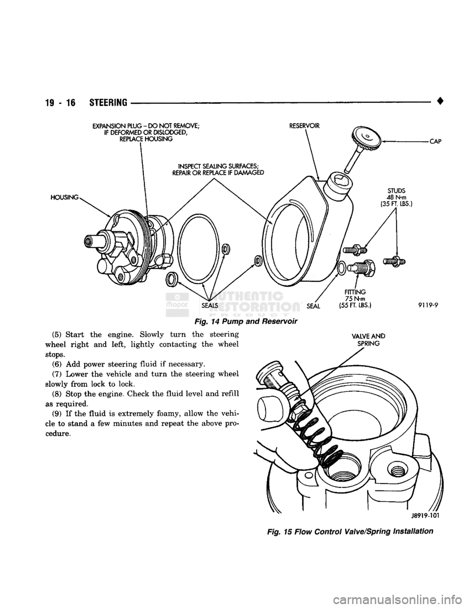
(1) Remove the filler cap and drain the fluid from
reservoir before removing parts. (2) Remove mounting studs and pressure fitting
(Fig. 14). Rock reservoir by hand or use a soft face
mallet to remove. STEERING 19-15
Fig.
13 Pulley
Installation
(Typical)
(3) Remove O-ring seals from housing and reser
voir (Fig. 14). (4) Remove flow control valve and spring from
housing.
INSTALLATION Clean all parts before installation. Lubricate
new O-ring seals with MOPAR® Power Steering Fluid or an equivalent product.
(1) Install flow control valve and spring (Fig. 15).
(2) Install new O-ring seals in housing (Fig. 15).
Tighten mounting studs to 48 N«m (35 ft. lbs.) torque.
(3) Install fitting in flow control valve bore.
Tighten the fitting to 75 N-m (55 ft. lbs.) torque.
POWER STEERING PUMP-INITIAL OPERATION
CAUTION:
The
fluid
level
should
be
checked
with
engine
off to
prevent
injury
from
moving
compo
nents.
Use
only
MOPAR®
Power
Steering
Fluid.
Do
not
use
automatic
transmission
fluid.
Do not
over
fill.
Wipe filler cap clean, then check the fluid level.
The dipstick should indicate FULL COLD when the fluid is at normal temperature. (1) Fill the pump fluid reservoir to the proper level
and let the fluid settle for at least two (2) minutes. (2) Start the engine and let run for a few seconds.
The turn the engine off. (3) Add fluid if necessary. Repeat the above proce
dure until the fluid level remains constant after run
ning the engine. (4) Raise the front wheels off the ground.
PUMP PULLEY
REMOVAL
(1) Remove the pulley with Puller C-4333 (Fig.
12).
Page 977 of 1502
19
- 16
STEERING
•
EXPANSION PLUG
-
DO NOT
REMOVE; IF DEFORMED
OR
DISLODGED,
REPLACE
HOUSING
RESERVOIR
HOUSING
CAP
SEAL FITTING
75 N-m
(55
FT.
LBS.)
9119-9
(5)
Start the engine. Slowly turn
wheel right and left, lightly contacting the wheel
stops.
(6) Add power steering fluid if necessary.
(7) Lower the vehicle and turn the steering wheel
slowly from lock to lock. (8) Stop the engine. Check the fluid level and refill
as required. (9) If the fluid is extremely foamy, allow the vehi
cle to stand a few minutes and repeat the above pro cedure.
Fig.
14
Pump
and Reservoir
the steering
VALVE
AND
SPRING
J8919-101
Fig.
15 Flow Control Valve/Spring
Installation
Page 981 of 1502
19-20
STEERING
•
RECIRCULATING BALL POWER STEERING GEAR
INDEX
page
Adjuster
Plug Assembly Replacement
26
Check
Valve Replacement
32
Gear
Disassembly
Information
23
Housing
End
Plug
25
Pitman Shaft
and
Side Cover Replacement
25
Pitman Shaft
Seals
— in
Car
Replacement
..... 20
page
Pitman Shaft
Seals
and
Bearing Replacement
. . . 31
Rack
Piston
and
Worm Shaft Replacement
..... 29
Service
Information
20
Steering Gear Adjustments
22
Steering Gear Replacement
32
Valve
Replacement
27
SERVICE
INFORMATION
A recirculating-ball steering gear
is
used with
the
power (assisted) steering system.
The
power steering gear
can be
adjusted
and
internally serviced.
PITMAN
SHAFT
SEALS
- IN
CAR
REPLACEMENT
REMOVAL (1)
Remove pitman
arm
from gear. Refer
to
Pit
man
Arm
Removal
in
Steering Linkage.
(2)
Clean exposed
end of
pitman shaft
and
housing.
Use
a
wire brush
to
clean
the
shaft splines. (3) Remove retaining ring with snap ring pliers
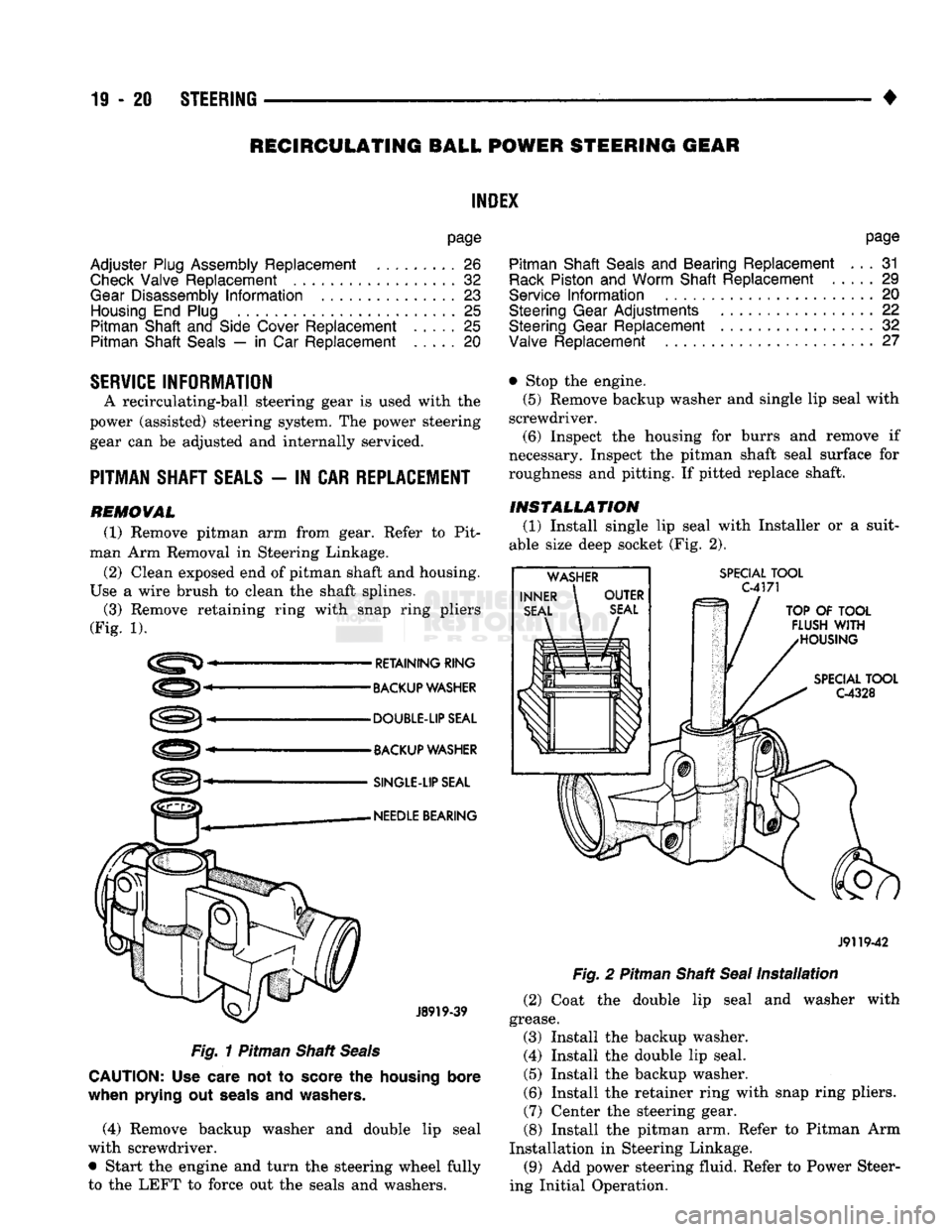
(Fig.
1).
RETAINING RING
BACKUP
WASHER
DOUBLE-UP SEAL
BACKUP
WASHER
SINGLE-LIP
SEAL
NEEDLE
BEARING
J8919-39
Fig.
1
Pitman Shaft
Seals
CAUTION:
Use
care
not to
score
the
housing bore
when prying
out
seals
and
washers.
(4) Remove backup washer
and
double
lip
seal
with screwdriver.
• Start
the
engine
and
turn
the
steering wheel fully
to
the
LEFT
to
force
out the
seals
and
washers. • Stop
the
engine.
(5)
Remove backup washer
and
single
lip
seal with
screwdriver.
(6)
Inspect
the
housing
for
burrs
and
remove
if
necessary. Inspect
the
pitman shaft seal surface
for
roughness
and
pitting.
If
pitted replace shaft.
INSTALLATION
(1)
Install single
lip
seal with Installer
or a
suit
able size deep socket
(Fig. 2).
SPECIAL
TOOL
C4171
TOP
OF
TOOL
FLUSH
WITH
HOUSING
SPECIAL
TOOL
G4328
J9119-42
Fig.
2
Pitman Shaft
Seal
Installation
(2)
Coat
the
double
lip
seal
and
washer with
grease.
(3) Install
the
backup washer.
(4) Install
the
double
lip
seal.
(5)
Install
the
backup washer.
(6)
Install
the
retainer ring with snap ring pliers. (7) Center
the
steering gear.
(8) Install
the
pitman
arm.
Refer
to
Pitman
Arm
Installation
in
Steering Linkage. (9)
Add
power steering fluid. Refer
to
Power Steer
ing Initial Operation.
Page 983 of 1502
19 - 22
STEERING
——— —
WORM THRUST BEARING PRELOAD
ADJUSTMENT
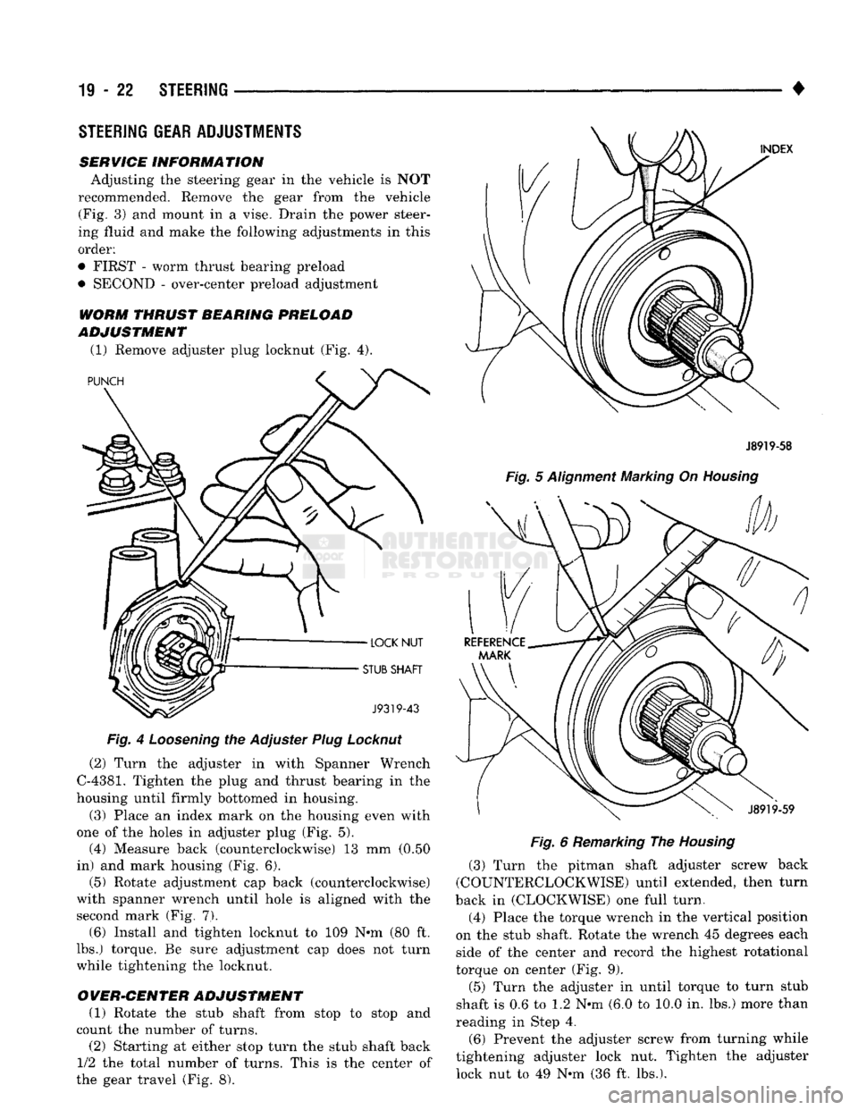
(1) Remove adjuster plug locknut (Fig. 4).
Fig.
4
Loosening
the Adjuster
Plug
Locknut
(2) Turn the adjuster in with Spanner Wrench
C-4381.
Tighten the plug and thrust bearing in the
housing until firmly bottomed in housing.
(3) Place an index mark on the housing even with
one of the holes in adjuster plug (Fig. 5). (4) Measure back (counterclockwise) 13 mm (0.50
in) and mark housing (Fig. 6). (5) Rotate adjustment cap back (counterclockwise)
with spanner wrench until hole is aligned with the
second mark (Fig. 7). (6) Install and tighten locknut to 109 N-m (80 ft.
lbs.) torque. Be sure adjustment cap does not turn
while tightening the locknut.
OVER-CENTER ADJUSTMENT (1) Rotate the stub shaft from stop to stop and
count the number of turns.
(2) Starting at either stop turn the stub shaft back
1/2 the total number of turns. This is the center of
the gear travel (Fig. 8). •
J8919-58
Fig.
5
Alignment
Marking On
Housing
Fig.
6 Remarking The
Housing
(3) Turn the pitman shaft adjuster screw back
(COUNTERCLOCKWISE) until extended, then turn
back in (CLOCKWISE) one full turn.
(4) Place the torque wrench in the vertical position
on the stub shaft. Rotate the wrench 45 degrees each
side of the center and record the highest rotational
torque on center (Fig. 9).
(5) Turn the adjuster in until torque to turn stub
shaft is 0.6 to 1.2 N-m (6.0 to 10.0 in. lbs.) more than
reading in Step 4.
(6) Prevent the adjuster screw from turning while
tightening adjuster lock nut. Tighten the adjuster lock nut to 49 N-m (36 ft. lbs.).
STEERING
GEAR
ADJUSTMENTS
SERVICE
INFORMATION
Adjusting the steering gear in the vehicle is NOT
recommended. Remove the gear from the vehicle (Fig. 3) and mount in a vise. Drain the power steer
ing fluid and make the following adjustments in this
order:
• FIRST - worm thrust bearing preload
• SECOND - over-center preload adjustment