drain bolt DODGE TRUCK 1993 Service Service Manual
[x] Cancel search | Manufacturer: DODGE, Model Year: 1993, Model line: TRUCK, Model: DODGE TRUCK 1993Pages: 1502, PDF Size: 80.97 MB
Page 698 of 1502
•
5.9L
ENGINE
9 - 93
Fig.
14
Removing
Distributor Driveshaft
Bushing
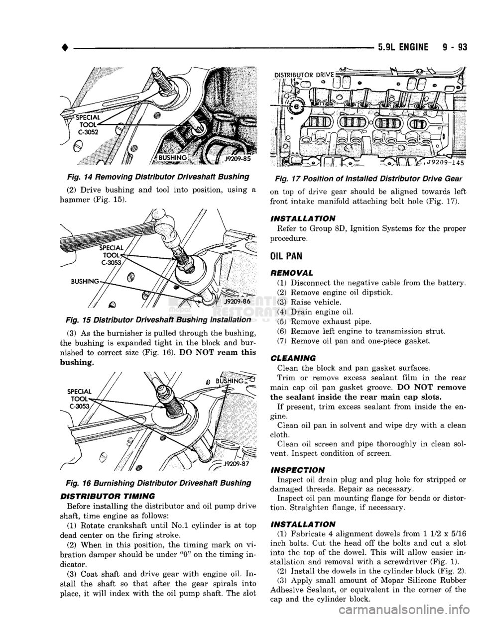
(2) Drive bushing and tool into position, using a
hammer (Fig. 15).
Fig.
15 Distributor Driveshaft
Bushing
Installation
(3) As the burnisher is pulled through the bushing,
the bushing is expanded tight in the block and bur nished to correct size (Fig. 16). DO NOT ream this
bushing.
Fig.
16
Burnishing
Distributor Driveshaft
Bushing
DISTRIBUTOR
TIMING
Before installing the distributor and oil pump drive
shaft, time engine as follows: (1) Rotate crankshaft until No.l cylinder is at top
dead center on the firing stroke. (2) When in this position, the timing mark on vi
bration damper should be under "0" on the timing in dicator.
(3) Coat shaft and drive gear with engine oil. In
stall the shaft so that after the gear spirals into
place, it will index with the oil pump shaft. The slot
Fig.
17 Position of Installed Distributor Drive Gear
on top of drive gear should be aligned towards left
front intake manifold attaching bolt hole (Fig. 17).
INSTALLATION
Refer to Group 8D, Ignition Systems for the proper
procedure.
OIL
PAN
REMOVAL
(1) Disconnect the negative cable from the battery.
(2) Remove engine oil dipstick.
(3) Raise vehicle.
(4) Drain engine oil. (5) Remove exhaust pipe.
(6) Remove left engine to transmission strut.
(7) Remove oil pan and one-piece gasket.
CLEANING
Clean the block and pan gasket surfaces.
Trim or remove excess sealant film in the rear
main cap oil pan gasket groove. DO NOT remove
the sealant inside the rear main cap slots.
If present, trim excess sealant from inside the en
gine.
Clean oil pan in solvent and wipe dry with a clean
cloth. Clean oil screen and pipe thoroughly in clean sol
vent. Inspect condition of screen.
INSPECTION
Inspect oil drain plug and plug hole for stripped or
damaged threads. Repair as necessary.
Inspect oil pan mounting flange for bends or distor
tion. Straighten flange, if necessary.
INSTALLATION
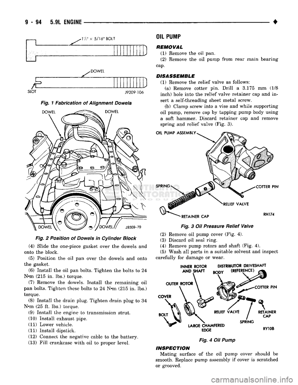
(1) Fabricate 4 alignment dowels from 1 1/2 x 5/16
inch bolts. Cut the head off the bolts and cut a slot into the top of the dowel. This will allow easier installation and removal with a screwdriver (Fig. 1).
(2) Install the dowels in the cylinder block (Fig. 2). (3) Apply small amount of Mopar Silicone Rubber
Adhesive Sealant, or equivalent in the corner of the cap and the cylinder block.
Page 699 of 1502
-17
" x
5/16" BOLT
DOWEL
E
SLOT J9209-106
Fig. 1 Fabrication of Alignment Dowels
DOWEL
^^^^
DOWEL
J9309-79
F/g.
2 Position of Dowels in Cylinder
Block
(4) Slide the one-piece gasket over the dowels and
onto the block.
(5) Position the oil pan over the dowels and onto
the gasket.
(6) Install the oil pan bolts. Tighten the bolts to 24
N*m (215 in. lbs.) torque.
(7) Remove the dowels. Install the remaining oil
pan bolts. Tighten these bolts to 24 Nmi (215 in. lbs.) torque.
(8) Install the drain plug. Tighten drain plug to 34
N-m (25 ft. lbs.) torque. (9) Install the engine to transmission strut.
(10) Install exhaust pipe.
(11) Lower vehicle.
(11) Install dipstick.
(12) Connect the negative cable to the battery.
(13) Fill crankcase with oil to proper level.
OIL
PU1P
REMOVAL
(1) Remove the oil pan.
(2) Remove the oil pump from rear main bearing
cap.
DISASSEMBLE
(1) Remove the relief valve as follows: (a) Remove cotter pin. Drill a 3.175 mm (1/8
inch) hole into the relief valve retainer cap and in
sert a self-threading sheet metal screw.
(b) Clamp screw into a vise and while supporting
oil pump, remove cap by tapping pump body using a soft hammer. Discard retainer cap and remove spring and relief valve (Fig. 3).
OIL PUMP ASSEMBLY
SPRING
COTTER
PIN
RELIEF VALVE
'
RETAINER CAP RH174
Fig.
3 Oil
Pressure
Relief
Valve
(2) Remove oil pump cover (Fig. 4).
(3) Discard oil seal ring.
(4) Remove pump rotors and shaft (Fig. 4).
(5) Wash all parts in a suitable solvent and inspect
carefully for damage or wear.
INNER ROTOR AND SHAFT DISTRIBUTOR DRIVESHAFT
BODY
(REFERENCE) COTTER
PIN
LARGE
CHAMFERED
EDGE
SPRING
RETAINER
CAP
RY10B
Fig.
4 Oil
Pump
INSPECTION
Mating surface of the oil pump cover should be
smooth. Replace pump assembly If cover is scratched
or grooved.
Page 711 of 1502
TORQUE
SPECIFICATIONS
DESCRIPTION TORQUE DESCRIPTION
TORQUE
Adjusting Strap Bolt 23 N-m (200 in. lbs.)
Camshaft Bolt 68 N-m (50
ft.
lbs.)
Camshaft Thrust Plate Bolts 24 N-m (210 in. lbs.)
Chain Case Cover Bolts 41 N-m (30 ft. lbs.)
Connecting Rod Cap Bolts.. 61 N-m (45 ft. lbs.)
Crankshaft Main Bearing Cap Bolts 115 N-m (85 ft. lbs.)
Cylinder Head Bolts 1st Step 68
N-m
(50 ft. lbs.)
2nd Step 143 N-m (105 ft. lbs.)
Cylinder Head Cover Bolts .......................... 11 N-m (95 in. lbs.)
Exhaust Manifold-to-Cylinder Head Bolts/Nuts 34 N-m (25 ft. lbs.)
Front Insulator Attaching Bolts (2WD) 41 N-m (30 ft. lbs.)
Front Insulator Stud Nuts 102 N-m (75 ft. lbs.)
Front Mount Adaptor-to-Block Bolts 41 N-m (30 ft. lbs.)
Front Mount Bracket-to- Crossmember Bolts (4WD) 41 N-m (30 ft. lbs.)
Generator Mounting Bolt 41 N-m (30 ft. lbs.)
Intake Manifold Bolts Refer to Procedure in Service Manual.
Oil Pan Bolts 23 N-m (200 in. lbs.)
Oil Pan Drain Plug 34 N-m (25 ft. lbs.)
Oil Pump Attaching Bolts 41 N-m (30 ft. lbs.)
Oil Pump Cover Bolts 11 N-m (95 in. lbs.) Rear Insulator-to-Bracket
Through-Bolt (2WD) 68 N-m (50 ft. lbs.
Rear Insulator-to-Crossmember Support Bracket Nut
(2WD)
41
N-m (30
ft.
lbs.
Rear Insulator Mounting Plate-fo- Rail Assembly Nuts (4WD) 41 N-m (30
ft.
lbs.
Rear Support Bracket-to-Crossmember Flange Nuts 41 N-m (30
ft.
lbs.
Rear Support Plate-to-lnsulator Mounting Plate Bolts (4WD) 41 N-m (30
ft.
lbs.
Rear Support Plate-to-Transfer Case Bolts 41 N-m (30
ft.
lbs.
Rocker Arm Bolts 23 N-m (200 in. lbs.
Spark Plugs....... 41 N-m (30
ft.
lbs.
Starter Mounting Bolts. 68 N-m (50
ft.
lbs.
Throttle Body Bolts (MPI) 23 N-m (200 in. lbs.
Torque Converter Drive Plate Bolts 31 N-m (270 in. lbs.
Transfer Case-to-lnsulator Mounting Plate Nuts... 204 N-m (150
ft.
lbs.
Transmission Support Bracket Bolts (2WD) 68 N-m (50
ft.
lbs.
Transmission Support Spacer Bolts (4WD) 68 N-m (50 ft. lbs.
Transmission Support Spacer-to- insulator Mounting Plate Nuts (4WD) .... 204 N-m (150 ft. lbs.
Vibration Damper Retainer Bolt 183 N-m (135 ft. lbs.
Water Pump-to-Chain Case Cover Bolt 41 N-m (30 ft. lbs.)
J9309-98
Page 714 of 1502
•
5.9L
(DIESEL) ENGINE
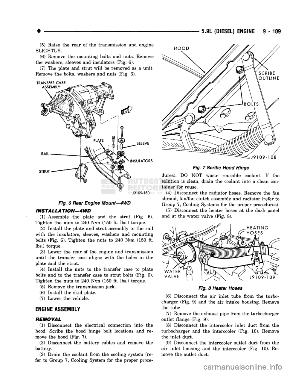
9 - 109 (5) Raise the rear of the transmission and engine
SLIGHTLY.
(6)
Remove the mounting bolts and nuts. Remove
the washers, sleeves and insulators (Fig. 6). (7) The plate and strut will be removed as a unit.
Remove the bolts, washers and nuts (Fig. 6).
J9109-150
Fig.
6 Rear
Engine
Mount—4WD
INSTALL A
TION—4
WD
(1) Assemble the plate and the strut (Fig. 6).
Tighten the nuts to 240 N-m (150 ft. lbs.) torque.
(2) Install the plate and strut assembly to the rail
with the insulators, sleeves, washers and mounting
bolts (Fig. 6). Tighten the nuts to 240 N-m (150 ft. lbs.) torque.
(3) Lower the rear of the engine and transmission
until the transfer case aligns with the holes in the
plate and the strut.
(4) Install the nuts to the transfer case to plate
bolts and to the transfer case to strut bolts (Fig. 6). Tighten the nuts to 240 N-m (150 ft. lbs.) torque.
(5) Remove the transmission jack.
(6) Install the skid plate.
(7) Lower the vehicle.
ENGINE
ASSEMBLY
REMOVAL
(1) Disconnect the electrical connection into the
hood. Scribe the hood hinge bolt locations and re
move the hood (Fig. 7).
(2) Disconnect the battery cables and remove the
battery.
(3) Drain the coolant from the cooling system (re
fer to Group 7, Cooling System for the proper proce-
Fig.
7
Scribe
Hood
Hinge
dures).
DO NOT waste reusable coolant. If the
solution is clean, drain the coolant into a clean con
tainer for reuse.
(4) Disconnect the radiator hoses. Remove the fan
shroud, fan/fan clutch assembly and radiator (refer to
Group 7, Cooling Systems for the proper procedures). (5) Disconnect the heater hoses at the dash panel
and at the water valve (Fig. 8).
Fig.
8 Heater
Hoses
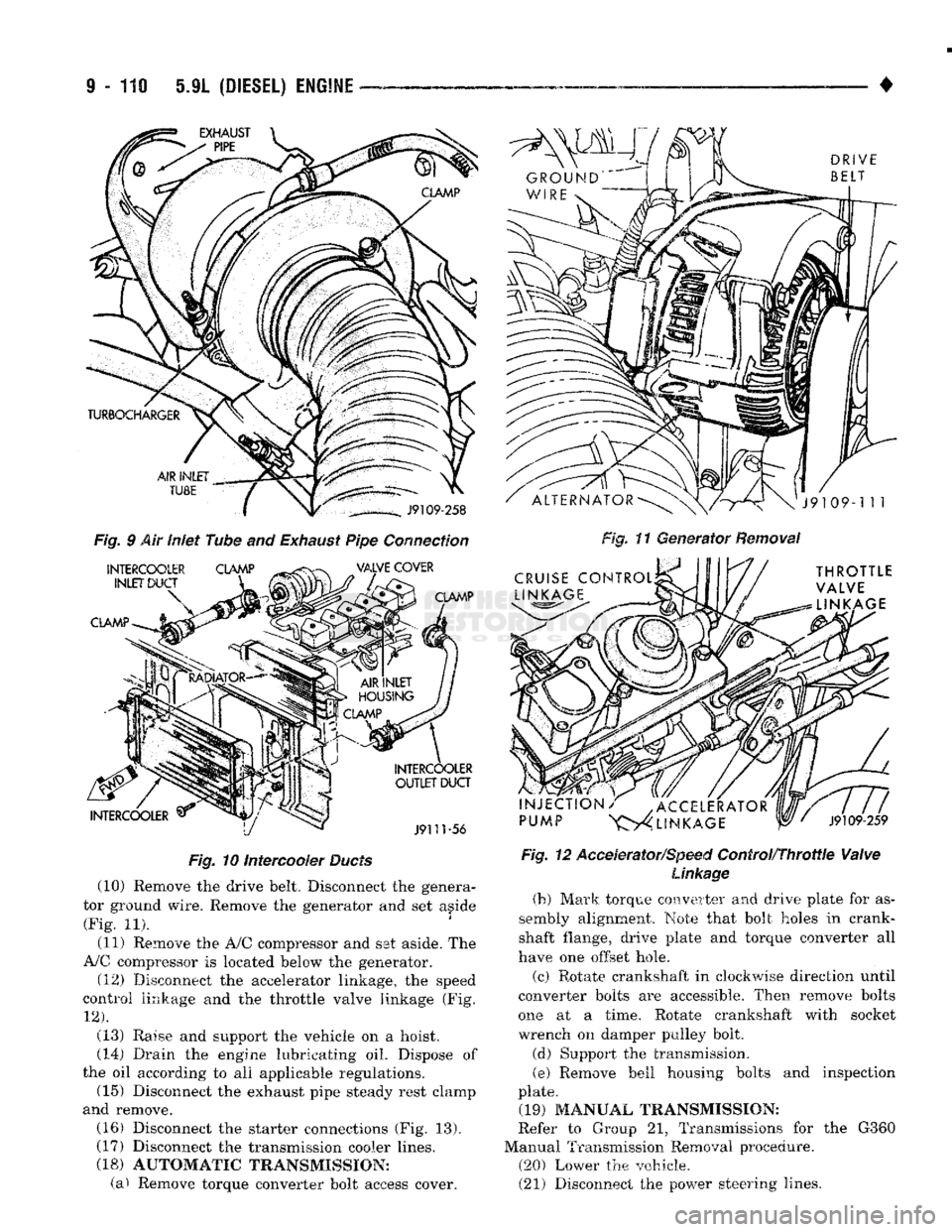
(6) Disconnect the air inlet tube from the turbo
charger (Fig. 9) and the air intake housing. Remove
the tube.
(7) Remove the exhaust pipe from the turbocharger
outlet flange (Fig. 9).
(8) Disconnect the intercooler inlet duct from the
turbocharger and the intercooler (Fig. 10). Remove
the inlet duct.
(9) Disconnect the intercooler outlet duct from the
air inlet housing and the intercooler (Fig. 10). Re
move the outlet duct.
Page 715 of 1502
9
- 119 5.9L
(DIESEL) ENGINE
Fig.
10 intercooler
Ducts
(10) Remove the drive belt. Disconnect the genera
tor ground wire. Remove the generator and set aside (Fig. 11).
(11) Remove the A/0 compressor and set aside. The
A/C compressor is located below the generator. (12) Disconnect the accelerator linkage, the speed
control linkage and the throttle valve linkage (Fig.
12).
(13) Raise and support the vehicle on a hoist.
(14)
Drain the engine lubricating oil. Dispose of
the oil according to all applicable regulations. (15) Disconnect the exhaust pipe steady rest clamp
and remove. (16) Disconnect the starter connections (Fig. 13).
(17) Disconnect the transmission cooler lines.
(18) AUTOMATIC TRANSMISSION: (a) Remove torque converter bolt access cover. •
Fig, 11 Generator Removal
Fig. 12 Accelerator/Speed
Control/Throttle
Valve
Linkage
(b) Mark
torque
converter and
drive
plate for
as
sembly
alignment.
Note
that bolt
holes
in crank
shaft flange, drive plate and torque converter all
have
one offset hole.
(c) Rotate crankshaft in clockwise direction until
converter
bolts
are accessible. Then remove
bolts
one
at a
time.
Rotate crankshaft with socket wrench on damper pulley bolt.
(d) Support the transmission.
(e)
Remove bell housing bolts and inspection
plate. (19) MANUAL TRANSMISSION:
Refer to Group 21, Transmissions for the G360
Manual Transmission Removal procedure. (20) Lower the vehicle.
(21) Disconnect the power steering lines.
Page 718 of 1502
•
5.9L
(DIESEL)
ENGINE
9 - 113
(3)
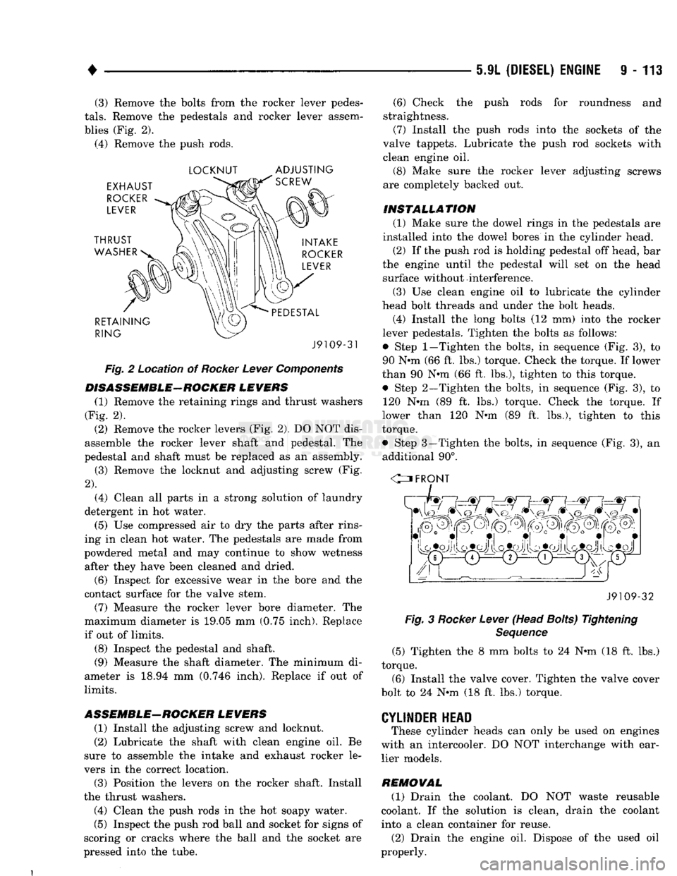
Remove the bolts from the rocker lever pedes
tals.
Remove the pedestals and rocker lever assem
blies (Fig. 2).
(4)
Remove the push rods.
LOCKNUT
ADJUSTING
J9109-31
Fig.
2 Location of
Rocker
Lever
Components
DISASSEMBLE—ROCKER
LEVERS
(1) Remove the retaining rings and thrust washers
(Fig. 2).
(2)
Remove the rocker levers (Fig. 2). DO NOT dis
assemble the rocker lever shaft and pedestal. The
pedestal and shaft must be replaced as an assembly.
(3)
Remove the locknut and adjusting screw (Fig.
2).
(4)
Clean all parts in a strong solution of laundry
detergent in hot water.
(5)
Use compressed air to dry the parts after rins
ing in clean hot water. The pedestals are made from
powdered metal and may continue to show wetness after they have been cleaned and dried.
(6)
Inspect for excessive wear in the bore and the
contact surface for the valve stem.
(7)
Measure the rocker lever bore diameter. The
maximum diameter is 19.05 mm (0.75 inch). Replace if out of limits.
(8) Inspect the pedestal and shaft.
(9) Measure the shaft diameter. The minimum di
ameter is 18.94 mm
(0.746
inch). Replace if out of
limits.
ASSEMBLE-ROCKER
LEVERS
(1) Install the adjusting screw and locknut.
(2)
Lubricate the shaft with clean engine oil. Be
sure to assemble the intake and exhaust rocker le
vers in the correct location.
(3)
Position the levers on the rocker shaft. Install
the thrust washers.
(4)
Clean the push rods in the hot soapy water.
(5)
Inspect the push rod ball and socket for signs of
scoring or cracks where the ball and the socket are
pressed into the tube.
(6)
Check the push rods for roundness and
straightness.
(7)
Install the push rods into the sockets of the
valve tappets. Lubricate the push rod sockets with clean engine oil.
(8) Make sure the rocker lever adjusting screws
are completely backed out.
INSTALLATION
(1) Make sure the dowel rings in the pedestals are
installed into the dowel bores in the cylinder head. (2) If the push rod is holding pedestal off head, bar
the engine until the pedestal will set on the head surface without interference.
(3)
Use clean engine oil to lubricate the cylinder
head bolt threads and under the bolt heads.
(4)
Install the long bolts (12 mm) into the rocker
lever pedestals. Tighten the bolts as follows:
• Step
1—Tighten
the bolts, in sequence (Fig. 3), to
90 N»m (66 ft. lbs.) torque. Check the torque. If lower
than 90 N»m (66 ft. lbs.), tighten to this torque.
• Step 2—Tighten the bolts, in sequence (Fig. 3), to 120 N-m (89 ft. lbs.) torque. Check the torque. If
lower than 120 N-m (89 ft. lbs.), tighten to this
torque.
• Step 3—Tighten the bolts, in sequence (Fig. 3), an additional 90°.
C=J FRONT
J9109-32
Fig.
3
Rocker
Lever
(Head Boits) Tightening
Sequence
(5)
Tighten the 8 mm bolts to 24 Nnn (18 ft. lbs.)
torque.
(6)
Install the valve cover. Tighten the valve cover
bolt to 24 Nnn (18 ft. lbs.) torque.
CYLINDER
HEAD
These cylinder heads can only be used on engines
with an intercooler. DO NOT interchange with ear lier models.
REMOVAL
(1) Drain the coolant. DO NOT waste reusable
coolant. If the solution is clean, drain the coolant into a clean container for reuse.
(2)
Drain the engine oil. Dispose of the used oil
properly.
Page 721 of 1502
9
- 116 5.9L
(DIESEL) ENGINE
•
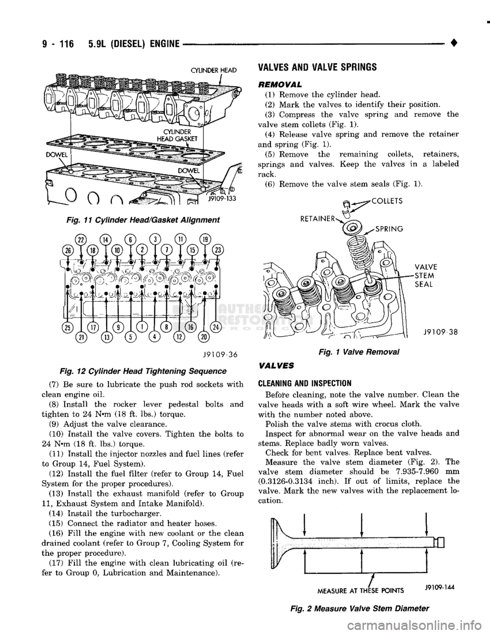
CYLINDER HEAD
Fig. 11 Cylinder Head/Gasket Alignment J9109-36
Fig. 12 Cylinder Head Tightening Sequence
(7) Be sure to lubricate the push rod sockets with
clean engine oil.
(8) Install the rocker lever pedestal bolts and
tighten to 24 N*m (18 ft. lbs.) torque. (9) Adjust the valve clearance.
(10) Install the valve covers. Tighten the bolts to
24 N*m (18 ft. lbs.) torque.
(11) Install the injector nozzles and fuel lines (refer
to Group 14, Fuel System).
(12) Install the fuel filter (refer to Group 14, Fuel
System for the proper procedures). (13) Install the exhaust manifold (refer to Group
11,
Exhaust System and Intake Manifold).
(14) Install the turbocharger.
(15) Connect the radiator and heater hoses. (16) Fill the engine with new coolant or the clean
drained coolant (refer to Group 7, Cooling System for
the proper procedure). (17) Fill the engine with clean lubricating oil (re
fer to Group 0, Lubrication and Maintenance).
VALVES
AND VALVE
SPRINGS
REMOWAL
(1) Remove the cylinder head.
(2) Mark the valves to identify their position.
(3) Compress the valve spring and remove the
valve stem collets (Fig. 1). (4) Release valve spring and remove the retainer
and spring (Fig. 1).
(5) Remove the remaining collets, retainers,
springs and valves. Keep the valves in a labeled
rack.
(6) Remove the valve stem seals (Fig. 1). -38
Fig. 1 Valve Removal
WALVES
CLEANING AND INSPECTION
Before cleaning, note the valve number. Clean the
valve heads with a soft wire wheel. Mark the valve
with the numbet* noted above.
Polish the valve stems with crocus cloth.
Inspect for abnormal wear on the valve heads and
stems.
Replace badly worn valves. Check for bent valves. Replace bent valves.
Measure the valve stem diameter (Fig. 2). The
valve stem diameter should be 7.935-7.960 mm (0.3126-0.3134 inch). If out of limits, replace the
valve. Mark the new valves with the replacement lo cation. Ik 1
MEASURE
AT THESE POINTS
Fig. 2 Measure Valve Stem Diameter
Page 749 of 1502
9 - 146 5.9L (DIESEL) ENGINE
•
DIAL
INDICATOR
CYLINDER BLOCK
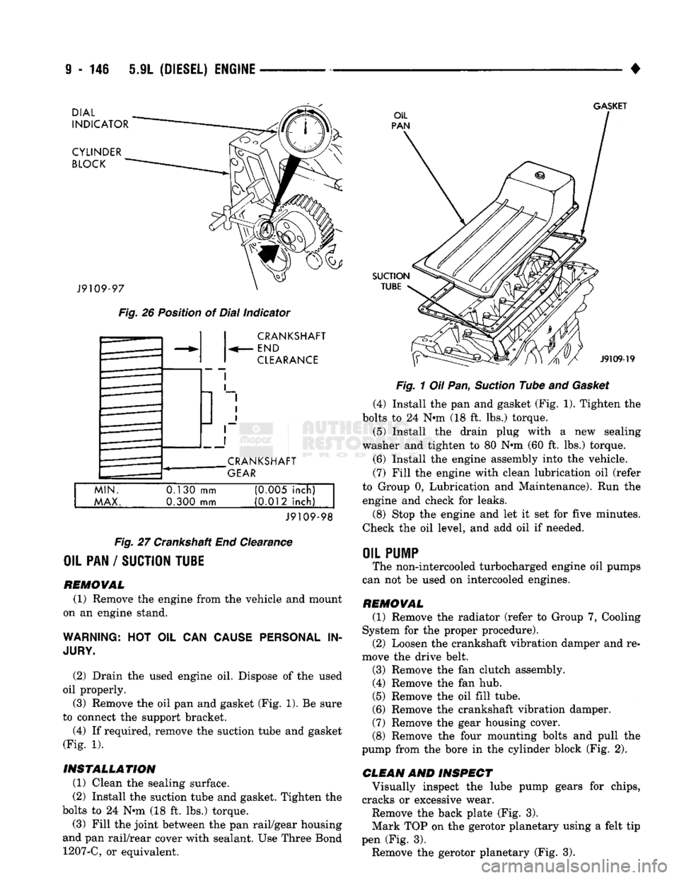
GASKET
J9109-97
Fig.
26 Position of Dial Indicator CRANKSHAFT
END
CLEARANCE
CRANKSHAFT
GEAR
MIN.
MAX.
0.130
mm
0.300 mm (0M5 inch)
(0.012 inch)
J9109-98
Fig.
27 Crankshaft End Clearance
OIL PAN / SUCTION TU1E
REMOVAL (1) Remove the engine from the vehicle and mount
on an engine stand.
WARNING:
HOT OIL CAN
CAUSE PERSONAL
IN
JURY.
(2) Drain the used engine oil. Dispose of the used
oil properly. (3) Remove the oil pan and gasket (Fig. 1). Be sure
to connect the support bracket.
(4) If required, remove the suction tube and gasket
(Fig. 1).
INSTALLATION (1) Clean the sealing surface.
(2) Install the suction tube and gasket. Tighten the
bolts to 24 Nin (18 ft. lbs.) torque.
(3) Fill the joint between the pan rail/gear housing
and pan rail/rear cover with sealant. Use Three Bond 1207-C, or equivalent.
SUCTION
TUBE
J9109-19
Fig.
1 Oil Pan,
Suction
Tube and
Gasket
(4) Install the pan and gasket (Fig. 1). Tighten the
bolts to 24 N-m (18 ft. lbs.) torque.
(5) Install the drain plug with
a
new sealing
washer and tighten to 80 Nnn (60 ft. lbs.) torque.
(6) Install the engine assembly into the vehicle.
(7) Fill the engine with clean lubrication oil (refer
to Group 0, Lubrication and Maintenance). Run the engine and check for leaks.
(8) Stop the engine and let it set for five minutes.
Check the oil level, and add oil if needed.
OIL
PUMP
The non-intercooled turbocharged engine oil pumps
can not be used on intercooled engines.
REMOVAL (1) Remove the radiator (refer to Group 7, Cooling
System for the proper procedure). (2) Loosen the crankshaft vibration damper and re
move the drive belt.
(3) Remove the fan clutch assembly. (4) Remove the fan hub.
(5) Remove the oil fill tube.
(6) Remove the crankshaft vibration damper.
(7) Remove the gear housing cover.
(8) Remove the four mounting bolts and pull the
pump from the bore in the cylinder block (Fig. 2).
CLEAN AND INSPECT Visually inspect the lube pump gears for chips,
cracks or excessive wear.
Remove the back plate (Fig. 3).
Mark TOP on the gerotor planetary using a felt tip
pen (Fig. 3). Remove the gerotor planetary (Fig. 3).
Page 751 of 1502
9
- 148 5.9L
(DIESEL) ENGINE
• Make sure the idler gear pin is installed in the lo
cating bore in the cylinder block. (2) Install the pump. Tighten the oil pump mount
ing bolts in two steps and in the sequence shown (Fig. 2).
• Step
1—Tighten
to 5 N«m (44 in. lbs.) torque.
• Step 2-Tighten to 24 N*m (18 ft. lbs.) torque. (3) The back plate on the pump seats against the
bottom of the bore in the cylinder block. When the
pump is correctly installed, the flange on the pump will not touch the cylinder block.
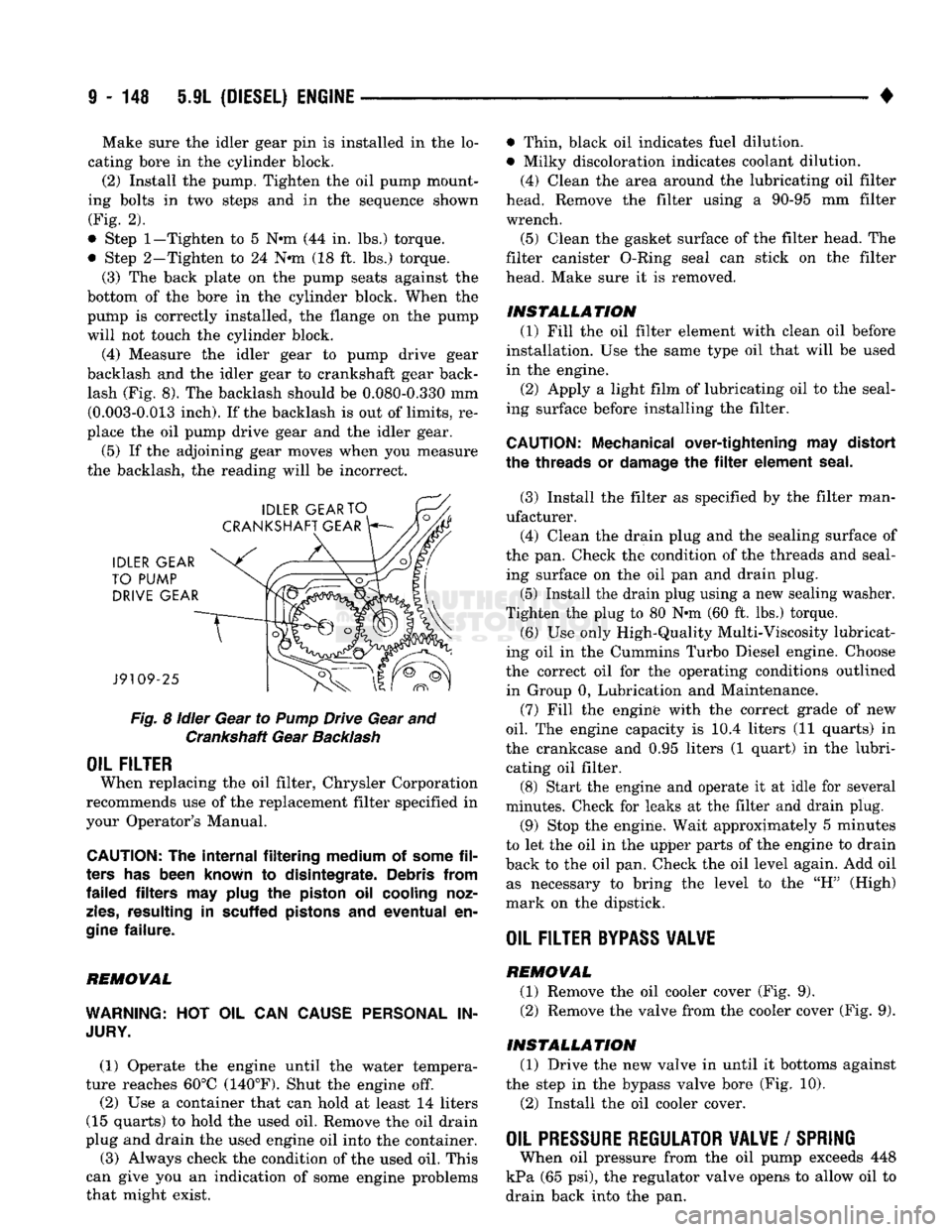
(4) Measure the idler gear to pump drive gear
backlash and the idler gear to crankshaft gear back lash (Fig. 8). The backlash should be 0.080-0.330 mm (0.003-0.013 inch). If the backlash is out of limits, re
place the oil pump drive gear and the idler gear.
(5) If the adjoining gear moves when you measure
the backlash, the reading will be incorrect.
Fig.
8
idler
Gear to
Pump
Drive Gear and Crankshaft Gear
Backlash
OIL FILTER
When replacing the oil filter, Chrysler Corporation
recommends use of the replacement filter specified in
your Operator's Manual.
CAUTION:
The
internal filtering medium
of
some
fil
ters
has
been known
to
disintegrate. Debris from
failed filters
may
plug
the
piston
oil
cooling noz
zles,
resulting
in
scuffed pistons
and
eventual
en
gine
failure.
REMOVAL
WARNING:
HOT OIL CAN
CAUSE PERSONAL
IN
JURY.
(1) Operate the engine until the water tempera
ture reaches 60°C (140°F). Shut the engine off.
(2) Use a container that can hold at least 14 liters
(15 quarts) to hold the used oil. Remove the oil drain
plug and drain the used engine oil into the container.
(3) Always check the condition of the used oil. This
can give you an indication of some engine problems
that might exist. • Thin, black oil indicates fuel dilution.
• Milky discoloration indicates coolant dilution.
(4) Clean the area around the lubricating oil filter
head. Remove the filter using a 90-95 mm filter
wrench.
(5) Clean the gasket surface of the filter head. The
filter canister O-Ring seal can stick on the filter
head. Make sure it is removed.
INSTALLATION (1) Fill the oil filter element with clean oil before
installation. Use the same type oil that will be used
in the engine.
(2) Apply a light film of lubricating oil to the seal
ing surface before installing the filter.
CAUTION:
Mechanical over-tightening
may
distort
the threads
or
damage
the filter
element seal.
(3) Install the filter as specified by the filter man
ufacturer. (4) Clean the drain plug and the sealing surface of
the pan. Check the condition of the threads and seal ing surface on the oil pan and drain plug.
(5) Install the drain plug using a new sealing washer.
Tighten the plug to 80 N-m (60 ft. lbs.) torque.
(6) Use only High-Quality Multi-Viscosity lubricat
ing oil in the Cummins Turbo Diesel engine. Choose
the correct oil for the operating conditions outlined in Group 0, Lubrication and Maintenance.
(7) Fill the enginfe with the correct grade of new
oil.
The engine capacity is i0.4 liters (11 quarts) in
the crankcase and 0.95 liters (1 quart) in the lubri cating oil filter. (8) Start the engine and operate it at idle for several
minutes. Check for leaks at the filter and drain plug.
(9) Stop the engine. Wait approximately 5 minutes
to let the oil in the upper parts of the engine to drain
back to the oil pan. Check the oil level again. Add oil as necessary to bring the level to the "H" (High)
mark on the dipstick.
OIL FILTER
BYPASS
VALWE
REMOVAL
(1) Remove the oil cooler cover (Fig. 9). (2) Remove the valve from the cooler cover (Fig. 9).
INSTALLATION (1) Drive the new valve in until it bottoms against
the step in the bypass valve bore (Fig. 10).
(2) Install the oil cooler cover.
OIL PRESSURE REGULATOR VALVE
/
SPRING
When oil pressure from the oil pump exceeds 448
kPa (65 psi), the regulator valve opens to allow oil to
drain back into the pan.
Page 757 of 1502
9
- 154 5.9L
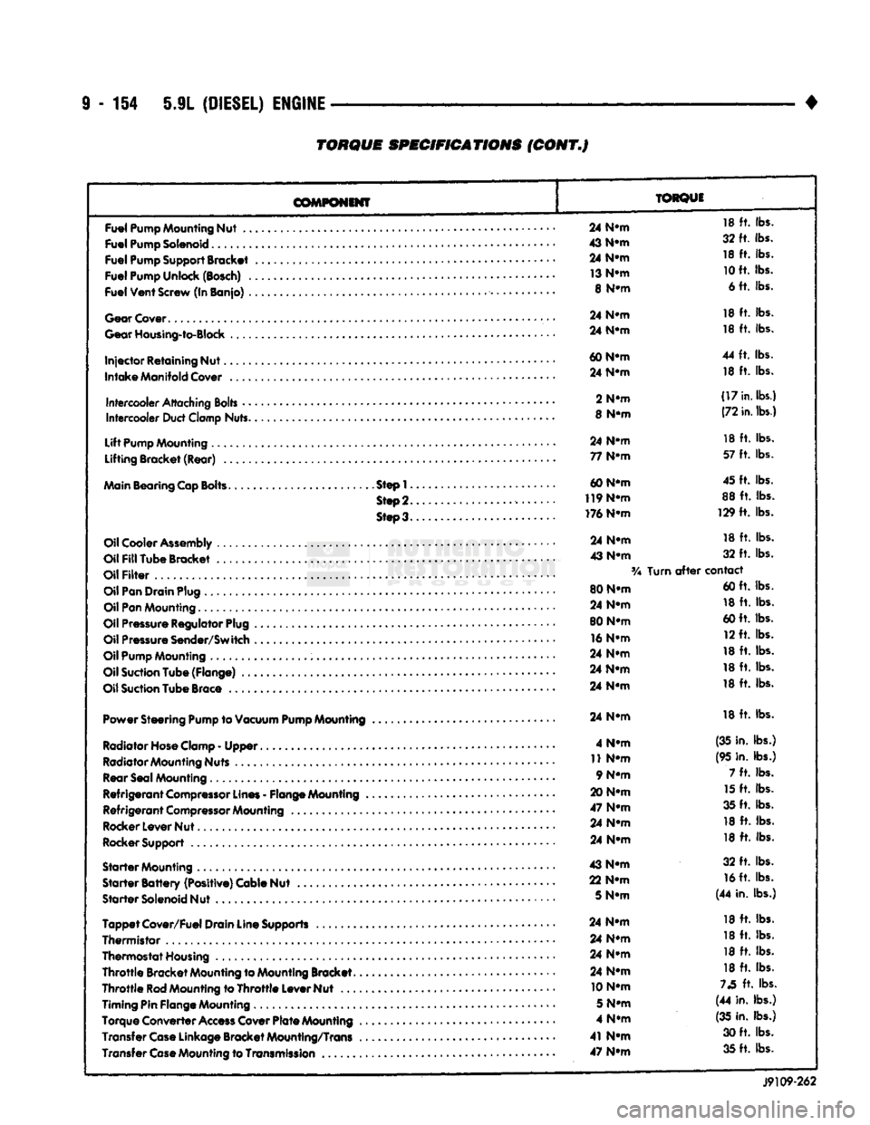
(DIESEL)
ENGINE
TORQUE
SPECIFICATIONS
(CONT.J
COMPONENT
TORQUE
Fuel
Pump
Mounting
Nut
..
Fuel
Pump
Solenoid
Fuel
Pump
Support
Bracket
Fuel
Pump
Unlock
(Bosch)
.
Fuel
Vent
Screw
(In Banjo)
.
Gear
Cover
Gear
Housing-to-Block
Injector
Retaining Nut.
Intake
Manifold
Cover
Intercooler
Attaching
Bolts
•
•
Intercooler
Duct
Clamp
Nuts.
Lift
Pump
Mounting
Lifting Bracket (Rear)
..
Main
Bearing
Cap
Bolts.
Step!.
Step
2.
Steo3.
Oil
Cooler
Assembly
Oil
Fill
Tube Bracket
Oil
Filter
Oil
Pan
Drain
Plug
Oil
Pan
Mounting.........
Oil
Pressure
Regulator
Plug
Oil
Pressure
Sender/Switch
Oil
Pump
Mounting
Oil
Suction
Tube (Flange)
..
Oil
Suction
Tube
Brace
Power Steering
Pump
to
Vacuum
Pump
Mounting
Radiator Hose Clamp
-
Upper
Radiator Mounting Nuts Rear Seal Mounting
Refrigerant
Compressor
Lines
-
Flange Mounting
Refrigerant
Compressor
Mounting
Rocker Lever Nut
Rocker Support
Starter
Mounting
Starter
Battery
(Positive) Cable Nut
Starter
Solenoid Nut
Tappet
Cover/Fuel Drain Line Supports
Thermistor
,
Thermostat Housing
Throttle
Bracket Mounting to Mounting Bracket.
Throttle
Rod
Mounting to
Throttle
Lever Nut
...
Timing Pin Flange Mounting
Torque Converter
Access
Cover
Plate
Mounting
Transfer
Case
Linkage Bracket Mounting/Trans Transfer
Case
Mounting to
Transmission
..
24
N-m
18
ft.
lbs.
43
N-m
32 ft. lbs.
24
N-m
18
ft.
lbs.
13
N-m
10
ft. lbs.
8
N-m
6 ft. lbs.
24
N-m
18
ft.
lbs.
24
N-m
18
ft.
lbs.
60
N-m
44
ft.
lbs.
24
N-m
18
ft.
lbs.
2
N-m
(17
in.
lbs.)
8
N-m
(72
in.
lbs.)
24
N-m
18
ft.
lbs.
77
N-m
57
ft.
lbs.
60 N-m 45 ft. lbs.
119
N-m
88
ft.
lbs.
176 N-m 129
ft.
lbs.
24
N-m
18
ft.
lbs.
43
N-m
32
ft.
lbs.
Turn
after
contact
80 N-m 60 ft. lbs.
24
N-m
18
ft.
lbs.
80 N-m 60 ft. lbs.
16
N-m
12 ft. lbs.
24
N-m
18
ft.
lbs.
24
N-m
18
ft.
lbs.
24
N-m
18
ft.
lbs.
24
N-m
18
ft.
lbs.
4
N-m
(35 in. lbs.)
11
N-m
(95 in. lbs.)
9 N-m 7
ft.
lbs.
20
N-m
15
ft.
lbs.
47
N-m
35 ft. lbs.
24
N-m
18
ft.
lbs.
24
N-m
18
ft.
lbs.
43
N-m
32
ft.
lbs.
22
N-m
16
ft. lbs.
5
N-m
(44 in. lbs.)
24
N-m
18
ft.
lbs.
24
N-m
18
ft.
lbs.
24
N-m
18
ft.
lbs.
24
N-m
18
ft.
lbs.
10 N-m
73
ft.
lbs.
5
N-m
(44 in. lbs.)
4
N-m
(35
in. lbs.)
41
N-m
30 ft. lbs.
47
N-m
35 ft. lbs.
J9109-262