drain bolt DODGE TRUCK 1993 Service Manual PDF
[x] Cancel search | Manufacturer: DODGE, Model Year: 1993, Model line: TRUCK, Model: DODGE TRUCK 1993Pages: 1502, PDF Size: 80.97 MB
Page 944 of 1502
• —_ —_
FUEL
SYSTEM
14 - 125
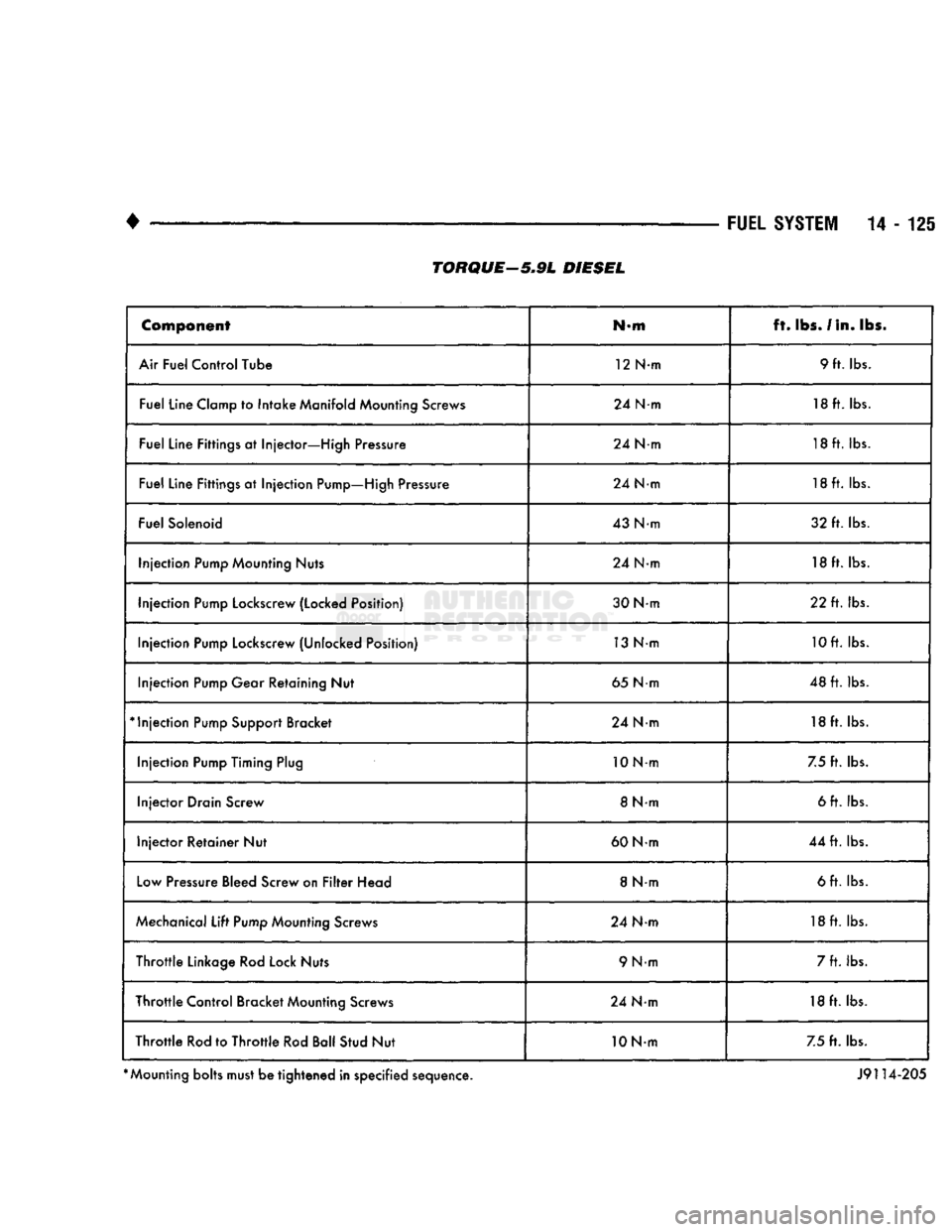
Component
N-m ft.
lbs.
/In. lbs.
Air Fuel Control Tube 12 N-m 9 ft. lbs.
Fuel Line Clamp to Intake Manifold Mounting Screws 24 N-m 18 ft. lbs.
Fuel Line Fittings at Injector—High Pressure 24 N-m 18ft. lbs.
Fuel Line Fittings at Injection Pump—High Pressure 24 N-m 18ft. lbs.
Fuel Solenoid 43 Nm 32 ft. lbs.
Injection Pump Mounting Nuts 24 N-m 18ft. lbs.
Injection Pump Lockscrew (Locked Position) 30 Nm 22 ft. lbs.
Injection Pump Lockscrew (Unlocked Position) 13 Nm 10ft. lbs.
Injection Pump Gear Retaining Nut 65 Nm 48 ft. lbs.
*
Injection Pump Support Bracket 24 Nm 18 ft. lbs.
Injection Pump Timing Plug 10Nm
7.5 ft. lbs.
Injector Drain Screw 8 N-m 6 ft. lbs.
Injector Retainer Nut 60 Nm 44 ft. lbs.
Low Pressure Bleed Screw on Filter Head 8 Nm 6 ft. lbs.
Mechanical Lift Pump Mounting Screws 24 Nm 18ft. lbs.
Throttle Linkage Rod Lock Nuts 9 N-m 7 ft. lbs.
Throttle Control Bracket Mounting Screws 24 Nm 18 ft. lbs.
Throttle Rod to Throttle Rod Ball Stud Nut 10 Nm 7.5 ft. lbs.
*
Mounting bolts must be tightened in specified sequence. J9114-205
TORQUE—5.9L
DIESEL
Page 973 of 1502
19
- 12
STEERING
• (5) Tighten fittings at pump and gear to 35 Nnn
(25 ft. lbs.) torque.
(6)
Install clamps on return hose on gear and
pump.
(7)
After installation, inspect and test for fluid
leaks.
PUMP REPLACEMENT—DIESEL ENGINE
REMOVAL
(1) Place a drain pan under the power steering
pump.
(2) Disconnect and cap the vacuum and steering
pump hoses.
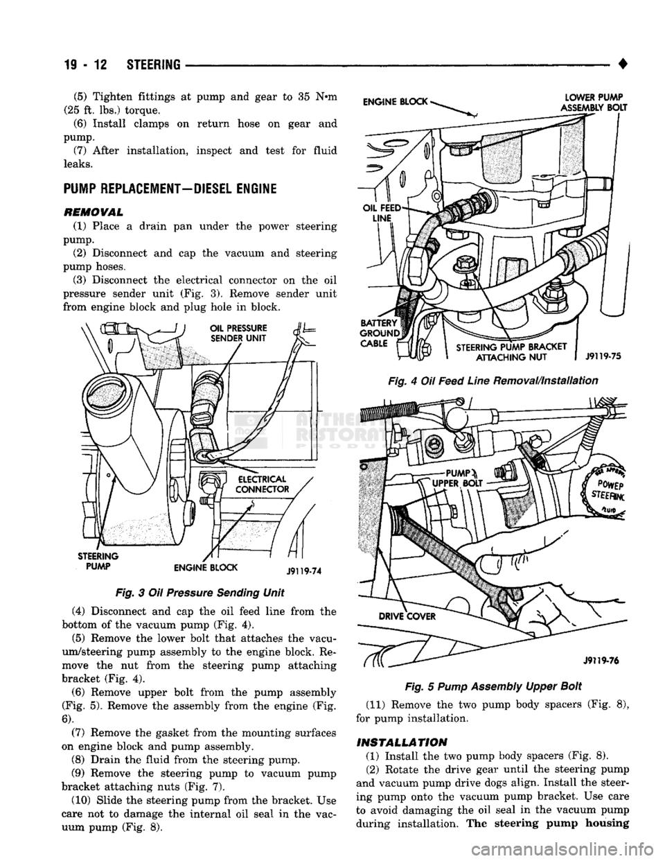
(3) Disconnect the electrical connector on the oil
pressure sender unit (Fig. 3). Remove sender unit
from engine block and plug hole in block.
PUMP ENGINE BLOCK Fig.
3 Oil
Pressure
Sending
Unit
(4) Disconnect and cap the oil feed line from the
bottom of the vacuum pump (Fig. 4). (5) Remove the lower bolt that attaches the vacu
um/steering pump assembly to the engine block. Re
move the nut from the steering pump attaching
bracket (Fig. 4).
(6)
Remove upper bolt from the pump assembly
(Fig. 5). Remove the assembly from the engine (Fig.
6).
(7) Remove the gasket from the mounting surfaces
on engine block and pump assembly.
(8) Drain the fluid from the steering pump.
(9) Remove the steering pump to vacuum pump
bracket attaching nuts (Fig. 7).
(10) Slide the steering pump from the bracket. Use
care not to damage the internal oil seal in the vac uum pump (Fig. 8).
Fig.
4 Oil
Feed
Line
Removal/Installation
Fig.
5
Pump
Assembly
Upper
Bolt
(11) Remove the two pump body spacers (Fig. 8),
for pump installation.
INSTALLATION (1) Install the two pump body spacers (Fig. 8).
(2) Rotate the drive gear until the steering pump
and vacuum pump drive dogs align. Install the steer
ing pump onto the vacuum pump bracket. Use care
to avoid damaging the oil seal in the vacuum pump during installation. The steering pump housing
Page 975 of 1502
19
- 14
STEERING
• (9) Install the fluid hoses to the power steering
pump, Tighten the pressure fitting at the pump to 30
N*m (22 ft. lbs.) torque.
(10) Install and clamp the hose on the vacuum
pump. (11) Fill the reservoir with power steering fluid
only. If necessary, refer to Pump Initial Operation
for detailed instructions.
(12) Start and run the engine. Check the operation
of the brakes, if necessary refer to Group 5, Brakes
for additional information.
PUMP REPLACEMENT—GASOLINE ENGINE
REMOVAL
WARNING:
DO NOT
REMOVE
THE
WATER PUMP COOLANT TUBE UNLESS
THE
COOLANT SYSTEM HAS BEEN DEPRESSUR1ZED
AND
DRAINED*
WARNING:
DO NOT
ATTEMPT
TO
REMOVE
THE
PUMP
WITHOUT
REMOVING
THE
BELT FIRST.
THE
AUTOMATIC TENSIONER
IS
UNDER
A
HIGH
SPRING
LOAD.
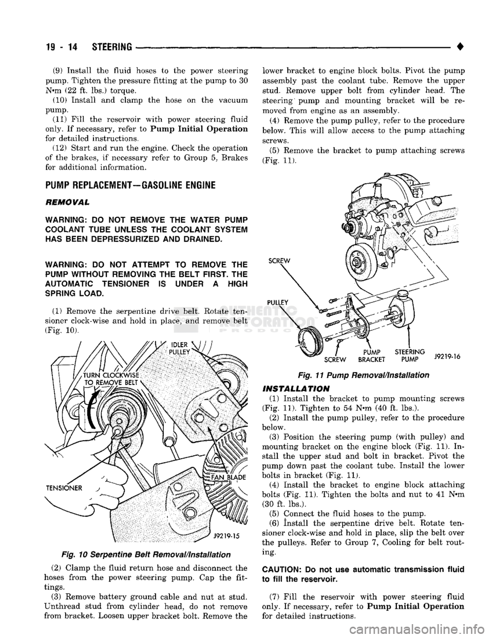
(1) Remove the serpentine drive belt. Rotate ten
sioner clock-wise and hold in place, and remove belt
(Fig. 10).
Fig.
10 Serpentine Belt Removal/Installation
(2) Clamp the fluid return hose and disconnect the
hoses from the power steering pump. Cap the fit
tings.
(3) Remove battery ground cable and nut at stud.
Unthread stud from cylinder head, do not remove
from bracket. Loosen upper bracket bolt. Remove the lower bracket to engine block bolts. Pivot the pump
assembly past the coolant tube. Remove the upper
stud. Remove upper bolt from cylinder head. The
steering pump and mounting bracket will be re
moved from engine as an assembly.
(4) Remove the pump pulley, refer to the procedure
below. This will allow access to the pump attaching screws.
(5)
Remove the bracket to pump attaching screws
(Fig. 11).
Fig.
11
Pump
Removal/Installation
INSTALLATION
(1) Install the bracket to pump mounting screws
(Fig. 11). Tighten to 54 N-m (40 ft. lbs.). (2) Install the pump pulley, refer to the procedure
below.
(3) Position the steering pump (with pulley) and
mounting bracket on the engine block (Fig. 11). In stall the upper stud and bolt in bracket. Pivot the
pump down past the coolant tube. Install the lower
bolts in bracket (Fig. 11). (4) Install the bracket to engine block attaching
bolts (Fig. 11). Tighten the bolts and nut to 41 N*m (30 ft. lbs.).
(5) Connect the fluid hoses to the pump. (6) Install the serpentine drive belt. Rotate ten
sioner clock-wise and hold in place, slip the belt over
the pulleys. Refer to Group 7, Cooling for belt rout ing.
CAUTION:
Do not use
automatic
transmission
fluid
to
fill the
reservoir.
(7) Fill the reservoir with power steering fluid
only. If necessary, refer to Pump Initial Operation
for detailed instructions.
Page 976 of 1502
#
_ ,
Fig.
12 Pulley
Removal
(Typical)
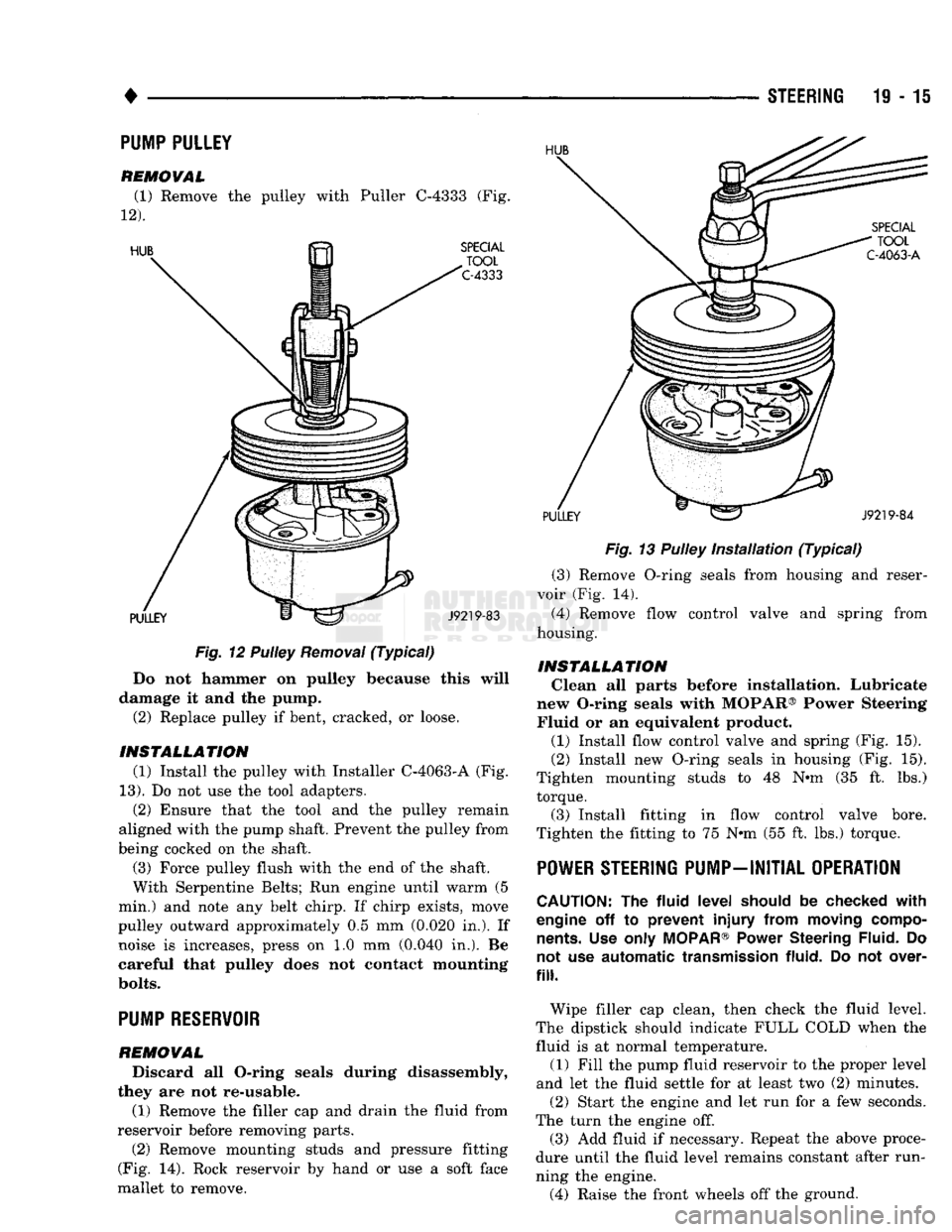
Do not hammer on pulley because this will
damage it and the pump. (2) Replace pulley if bent, cracked, or loose.
INSTALLATION (1) Install the pulley with Installer C-4063-A (Fig.
13).
Do not use the tool adapters. (2) Ensure that the tool and the pulley remain
aligned with the pump shaft. Prevent the pulley from
being cocked on the shaft.
(3) Force pulley flush with the end of the shaft.
With Serpentine Belts; Run engine until warm (5
min.) and note any belt chirp. If chirp exists, move
pulley outward approximately 0.5 mm (0.020 in.). If noise is increases, press on 1.0 mm (0.040 in.). Be
careful that pulley does not contact mounting
bolts.
PUMP RESERVOIR
REMOVAL
Discard all O-ring seals during disassembly,
they are not re-usable.
(1) Remove the filler cap and drain the fluid from
reservoir before removing parts. (2) Remove mounting studs and pressure fitting
(Fig. 14). Rock reservoir by hand or use a soft face
mallet to remove. STEERING 19-15
Fig.
13 Pulley
Installation
(Typical)
(3) Remove O-ring seals from housing and reser
voir (Fig. 14). (4) Remove flow control valve and spring from
housing.
INSTALLATION Clean all parts before installation. Lubricate
new O-ring seals with MOPAR® Power Steering Fluid or an equivalent product.
(1) Install flow control valve and spring (Fig. 15).
(2) Install new O-ring seals in housing (Fig. 15).
Tighten mounting studs to 48 N«m (35 ft. lbs.) torque.
(3) Install fitting in flow control valve bore.
Tighten the fitting to 75 N-m (55 ft. lbs.) torque.
POWER STEERING PUMP-INITIAL OPERATION
CAUTION:
The
fluid
level
should
be
checked
with
engine
off to
prevent
injury
from
moving
compo
nents.
Use
only
MOPAR®
Power
Steering
Fluid.
Do
not
use
automatic
transmission
fluid.
Do not
over
fill.
Wipe filler cap clean, then check the fluid level.
The dipstick should indicate FULL COLD when the fluid is at normal temperature. (1) Fill the pump fluid reservoir to the proper level
and let the fluid settle for at least two (2) minutes. (2) Start the engine and let run for a few seconds.
The turn the engine off. (3) Add fluid if necessary. Repeat the above proce
dure until the fluid level remains constant after run
ning the engine. (4) Raise the front wheels off the ground.
PUMP PULLEY
REMOVAL
(1) Remove the pulley with Puller C-4333 (Fig.
12).
Page 986 of 1502
•
STEERING
19 - 25
PITMAN
SHAFT AND SIDE COVER REPLACEMENT
REMOVE (1) Remove steering gear from vehicle. Refer to
Power Steering Gear Replacement in this section. (2) Remove pitman arm from steering gear. Refer
to Pitman Arm Removal in the Steering Linkage sec
tion.
(3) Rotate stub shaft back and forth to drain power
steering fluid.
DISASSEMBLE
• Clean exposed end of pitman shaft and housing.
• Clean pitman shaft spline with a wire brush.
(1) Remove preload adjuster nut.
(2) Rotate stub shaft with socket to center gear.
Remove side cover bolts. (3) Remove side cover, gasket and pitman shaft as
an assembly.
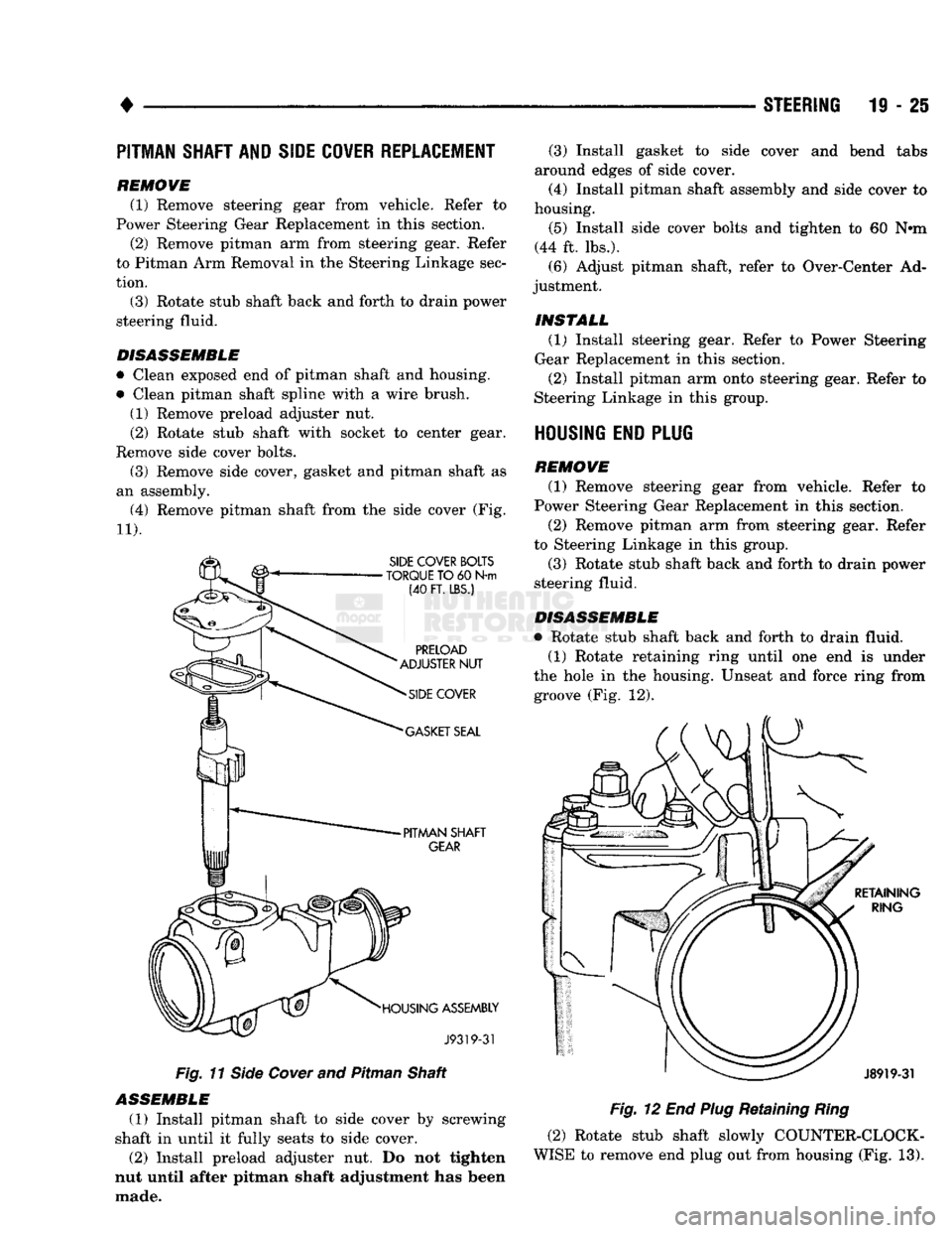
(4) Remove pitman shaft from the side cover (Fig.
11). Fig.
11
Side
Cover
and Pitman Shaft
ASSEMBLE
(1) Install pitman shaft to side cover by screwing
shaft in until it fully seats to side cover. (2) Install preload adjuster nut. Do not tighten
nut until after pitman shaft adjustment has been
made. (3) Install gasket to side cover and bend tabs
around edges of side cover.
(4) Install pitman shaft assembly and side cover to
housing.
(5) Install side cover bolts and tighten to 60 N»m
(44 ft. lbs.). (6) Adjust pitman shaft, refer to Over-Center Ad
justment.
INSTALL (1) Install steering gear. Refer to Power Steering
Gear Replacement in this section.
(2) Install pitman arm onto steering gear. Refer to
Steering Linkage in this group.
HOUSING END PLUG
REMOVE (1) Remove steering gear from vehicle. Refer to
Power Steering Gear Replacement in this section.
(2) Remove pitman arm from steering gear. Refer
to Steering Linkage in this group.
(3) Rotate stub shaft back and forth to drain power
steering fluid.
DISASSEMBLE
• Rotate stub shaft back and forth to drain fluid. (1) Rotate retaining ring until one end is under
the hole in the housing. Unseat and force ring from groove (Fig. 12).
Fig.
12 End
Plug
Retaining
Ring
(2) Rotate stub shaft slowly COUNTER-CLOCK
WISE to remove end plug out from housing (Fig. 13).
Page 1005 of 1502
21
- 4
NV4500 MANUAL TRANSMISSION
(12) If transmission is to be disassembled for re
pair, remove drain plug and drain lubricant from transmission.
(13) move bolts/nuts attaching transmission to rear
mount.
(14) Support transmission with a transmission
jack. Secure transmission to jack with safety chains.
(15) Remove rear crossmember,
(16) Remove bolts attaching clutch slave cylinder
to clutch housing. Then move cylinder aside for
working clearance.
(17) Remove transmission harness wires from clips
on transmission shift cover. (18) Remove bolts attaching transmission to clutch
housing. (19) Slide transmission and jack rearward until
drive gear clears clutch housing. (20) Lower transmission jack and remove trans
mission from under vehicle. (21) If transmission will be overhauled, clean
transmission exterior with solvent or with steam gun.
TRANSMISSION
INSTALLATION—2-WHEEL DRIVE
(1) Apply light coat of Mopar high temperature
bearing grease to contact surfaces of following com
ponents: • drive gear splines and pilot bearing hub
• release bearing slide surface of front retainer
• pilot bearing • release bearing bore
• release fork
• release fork ball stud
• propeller shaft slip yoke (2) Fill transmission with recommended lubricant.
Correct fill level is bottom edge of fill plug hole. (3) Mount transmission on jack and position trans
mission under vehicle. (4) Raise transmission until drive gear is centered
in release bearing and clutch disc hub. (5) Move transmission forward and start drive gear
in release bearing, clutch disc and pilot bushing. (6) Work transmission forward until seated against
clutch housing. Do not allow transmission to remain
unsupported after drive gear has entered clutch disc. (7) Install and tighten transmission-to-clutch hous
ing bolts to 108 N*m (80 ft. lbs.) torque. (8) Install clutch slave cylinder. (9) Connect speed sensor and backup light switch
wires.
(10) Position transmission harness wires in clips
on shift cover. (11) Install transmission mount on transmission or
rear crossmember. (12) Install rear crossmember.
(13) Remove transmission jack and engine support
fixture. (14) Align and connect propeller shaft. (15) Fill transmission with required lubricant, if
necessary. (16) Lower vehicle.
(17) Install shift lever on transmission stub lever.
(18) Install shift boot and bezel. (19) Connect battery negative cable.
TRANSMISSION REMOVAL—4-WHEEL DRIVE
(1) Disconnect battery negative cable.
(2) Shift transmission into Neutral.
(3) Remove shift lever boot and bezel. (4) Loosen nut attaching shift lever to transmis
sion stub lever and remove shift lever from stub le
ver. (5) Raise- vehicle.
(6) Remove skid plate if equipped.
(7) If transmission will be disassembled for repair,
remove drain plug and drain lubricant from trans
mission. (8) Mark propeller shafts and yokes for assembly
reference. (9) Disconnect propeller shafts and remove propel
ler shafts. (10) Disconnect and remove exhaust system
Y-pipe. Then disconnect and lower remaining ex
haust pipes for clearance as necessary. (11) Support engine with adjustable safety stand.
(12) Disconnect speed sensor wires and disconnect
speedometer cable, if equipped. (13) Disconnect backup light switch wires.
(14) Disconnect transfer case shift linkage at
transfer case range lever. (15) Remove bolts/nuts attaching transmission to
rear support. (16) Remove crossmember bolts/nuts and remove
crossmember. (17) Support transfer case with transmission jack.
Secure transfer case to jack with safety chains. (18) Remove transfer case attaching nuts.
(19) Move transfer case rearward until input gear
clears transmission mainshaft. (20) Lower transfer case assembly and move it
from under vehicle. (21) If transmission is being removed for repair,
remove drain plug and drain lubricant from trans mission.
(22) Support transmission with transmission jack.
Secure transmission to jack with safety chains.
(23) Remove transmission harness from retaining
clips on transmission shift cover. (24) Remove bolts/nuts attaching transmission
mount to rear crossmember.
(25) Remove rear crossmember.
(26) Remove clutch slave cylinder splash shield, if
equipped.
(27) Loosen clutch slave cylinder attaching nuts
until cylinder piston rod is clear of release lever.
This reduces pressure on lever and release bearing
Page 1044 of 1502
•
NV4500
TRANSMISSION OVERHAUL
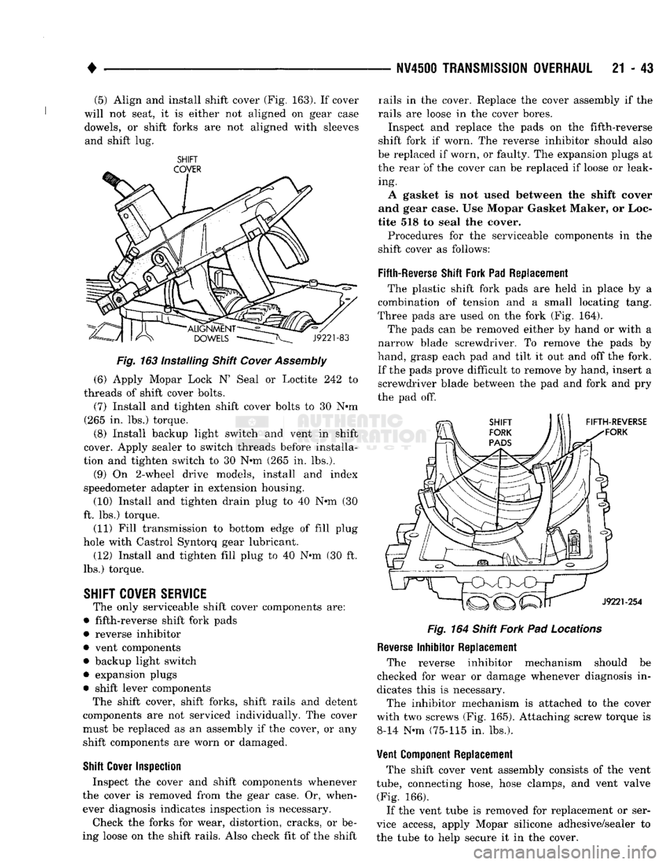
21 • 43 (5) Align and install shift cover (Fig. 163). If cover
will not seat, it is either not aligned on gear case
dowels, or shift forks are not aligned with sleeves and shift lug.
SHIFT
Fig.
163 Installing Shift
Cover
Assembly
(6) Apply Mopar Lock N' Seal or Loctite 242 to
threads of shift cover bolts. (7) Install and tighten shift cover bolts to 30 Nnn
(265 in. lbs.) torque.
(8) Install backup light switch and vent in shift
cover. Apply sealer to switch threads before installa
tion and tighten switch to 30 Nnn (265 in. lbs.).
(9) On 2-wheel drive models, install and index
speedometer adapter in extension housing. (10) Install and tighten drain plug to 40 Nnn (30
ft. lbs.) torque.
(11) Fill transmission to bottom edge of fill plug
hole with Castrol Syntorq gear lubricant.
(12) Install and tighten fill plug to 40 N-m (30 ft.
lbs.) torque.
SHIFT
COVER SERVICE
The only serviceable shift cover components are:
• fifth-reverse shift fork pads
• reverse inhibitor
• vent components • backup light switch
• expansion plugs
• shift lever components The shift cover, shift forks, shift rails and detent
components are not serviced individually. The cover
must be replaced as an assembly if the cover, or any shift components are worn or damaged.
Shift
Cover
Inspection
Inspect the cover and shift components whenever
the cover is removed from the gear case. Or, when ever diagnosis indicates inspection is necessary.
Check the forks for wear, distortion, cracks, or be
ing loose on the shift rails. Also check fit of the shift rails in the cover. Replace the cover assembly if the
rails are loose in the cover bores.
Inspect and replace the pads on the fifth-reverse
shift fork if worn. The reverse inhibitor should also
be replaced if worn, or faulty. The expansion plugs at
the rear of the cover can be replaced if loose or leak ing.
A gasket is not used between the shift cover
and gear case. Use Mopar Gasket Maker, or Loc
tite 518 to seal the cover.
Procedures for the serviceable components in the
shift cover as follows:
Fifth-Reverse
Shift
Fork Pad Replacement The plastic shift fork pads are held in place by a
combination of tension and a small locating tang.
Three pads are used on the fork (Fig. 164).
The pads can be removed either by hand or with a
narrow blade screwdriver. To remove the pads by
hand, grasp each pad and tilt it out and off the fork.
If the pads prove difficult to remove by hand, insert a screwdriver blade between the pad and fork and pry
the pad off.
Fig.
164 Shift
Fork
Pad
Locations
Reverse
Inhibitor Replacement The reverse inhibitor mechanism should be
checked for wear or damage whenever diagnosis in
dicates this is necessary.
The inhibitor mechanism is attached to the cover
with two screws (Fig. 165). Attaching screw torque is 8-14 N-m (75-115 in. lbs.).
Vent
Component
Replacement The shift cover vent assembly consists of the vent
tube,
connecting hose, hose clamps, and vent valve (Fig. 166).
If the vent tube is removed for replacement or ser
vice access, apply Mopar silicone adhesive/sealer to
the tube to help secure it in the cover.
Page 1048 of 1502
G360
MANUAL TRANSMISSION
21 - 47
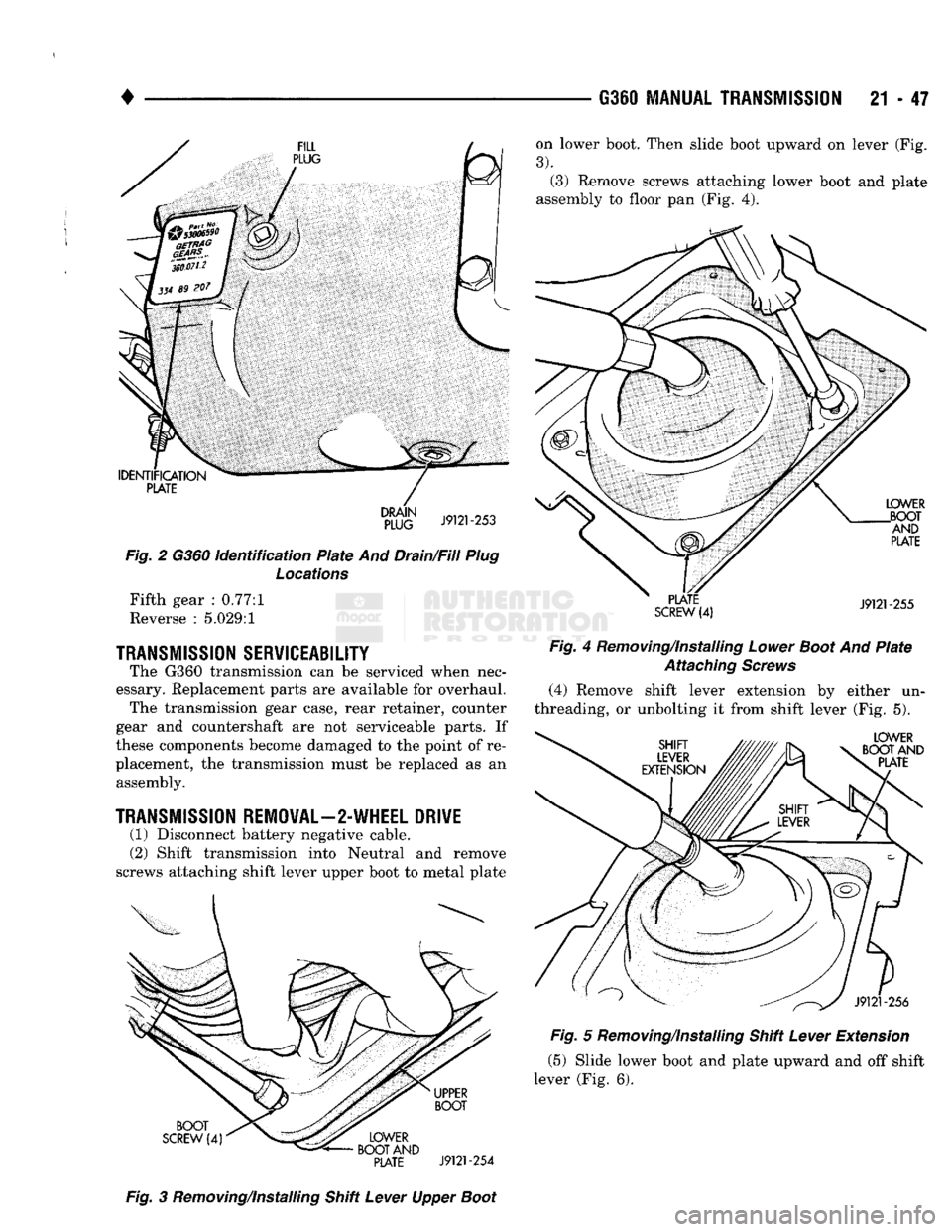
on lower boot. Then slide boot upward on lever (Fig.
3).
(3) Remove screws attaching lower boot and plate
assembly to floor pan (Fig. 4).
IDENTIFICATION
PLATE
Fig.
2 G360
identification
Plate
And Drain/Fill
Plug
Locations
Fifth gear : 0.77:1
Reverse : 5.029:1
TRANSMISSION
SERVICEABILITY
The G360 transmission can be serviced when nec
essary. Replacement parts are available for overhaul. The transmission gear case, rear retainer, counter
gear and countershaft are not serviceable parts. If
these components become damaged to the point of re
placement, the transmission must be replaced as an assembly.
TRANSMISSION
REMOVAL—2-WHEEL DRIVE
(1) Disconnect battery negative cable.
(2) Shift transmission into Neutral and remove
screws attaching shift lever upper boot to metal plate
PLATE
SCREW
(4)
LOWER
.BOOT AND
PLATE
J9121-255
Fig
4 Removing/Installing
Lower
Boot
And
Plate
Attaching
Screws
(4) Remove shift lever extension by either un
threading, or unbolting it from shift lever (Fig. 5).
LOWER
BOOT AND PLATE BOOT
SCREW
(4)
UPPER
BOOT
LOWER
BOOT AND
PLATE
J9121-254
J9121-256
Fig.
5 Removing/Installing Shift
Lever
Extension
(5) Slide lower boot and plate upward and off shift
lever (Fig. 6).
Fig.
3 Removing/Installing Shift
Lever
Upper
Boot
Page 1073 of 1502

21 - 72 G36Q
TRANSMISSION OVERHAUL
missions were not originally equipped with a cover
gasket, a gasket should be installed on these trans
missions).
(7)
Verify that synchronizer sleeves are in neutral
position. Shift cover cannot be installed otherwise.
(8)
Install shift cover. Align shift forks with syn
chro sleeves and alignment dowels and seat cover on
case. (9) Apply Mopar or Loctite thread locker to shift
cover bolts. Then install and tighten bolts to 22-30
N-m
(16-22
ft. lbs.) torque.
(10) Place transmission in level position and in
stall drain plug. Tighten plug to 47 N-m (35 ft. lbs.) (11) Fill transmission to bottom edge of fill plug
hole with Mopar 5W-30 engine oil.
(12) Install and tighten fill plug to 47 N-m (35 ft.
lbs.) torque.
(13) Install backup light switch in shift cover if re
moved. (14) Mount transmission on jack for installation in
vehicle.
(15) Secure transmission to jack with safety
chains.
(16) Apply thin coat of Mopar high temperature or
multi-purpose grease to pilot hub of input shaft.
Page 1093 of 1502
21
- 12
AUTOMATIC TRANSMISSION—32RH/36RH/37RH/42RH/46RH
•
Rear Servo
Test
Apply air pressure to the rear servo apply passage.
The servo rod should extend and cause the band to
tighten around the drum. Spring tension should re lease the servo when air pressure is removed.
CONVERTER
HOUSING
FLUID
LEAK
DIAGNOSIS
When diagnosing converter housing fluid leaks,
two items must be established before repair. First, it must be verified that a leak condition actually exists.
And second, the true source of the leak must be de
termined. Some suspected converter housing leaks may not
be leaks at all. They may only be the result of resid ual fluid in the converter housing, or excess fluid spilled during factory fill or refill after repair. Converter housing leaks have several potential
sources. Through careful observation, a leak source
can be identified before removing the transmission
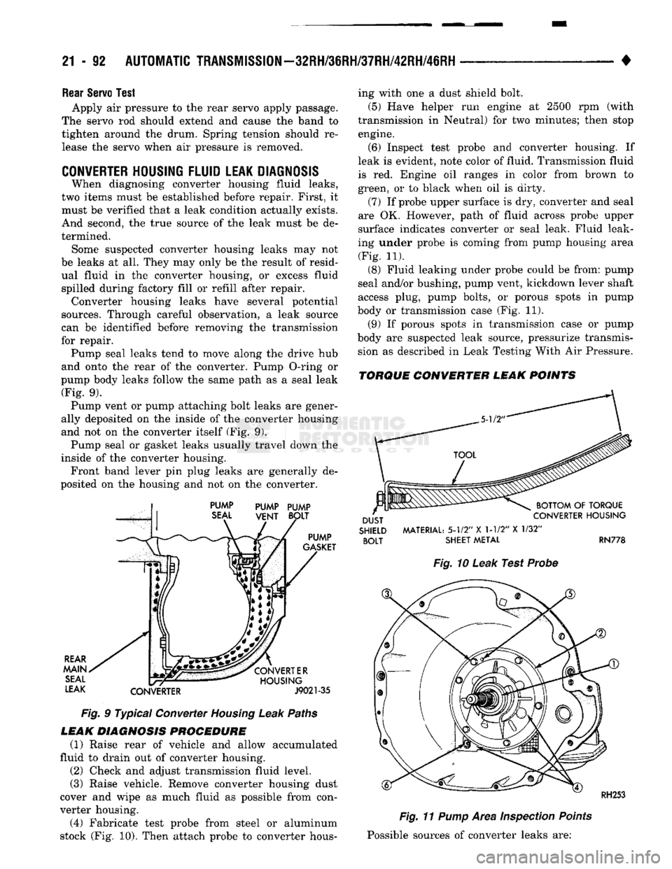
for repair. Pump seal leaks tend to move along the drive hub
and onto the rear of the converter. Pump O-ring or
pump body leaks follow the same path as a seal leak (Fig. 9). Pump vent or pump attaching bolt leaks are gener
ally deposited on the inside of the converter housing
and not on the converter itself (Fig. 9). Pump seal or gasket leaks usually travel down the
inside of the converter housing. Front band lever pin plug leaks are generally de
posited on the housing and not on the converter.
,j PUMP PUMP PUMP
Fig. 9 Typical Converter Homing Leak Paths
LEAK DIAGNOSIS PROCEDURE (1) Raise rear of vehicle and allow accumulated
fluid to drain out of converter housing.
(2) Check and adjust transmission fluid level.
(3)
Raise vehicle. Remove converter housing dust
cover and wipe as much fluid as possible from con
verter housing.
(4) Fabricate test probe from steel or aluminum
stock (Fig. 10). Then attach probe to converter hous ing with one a dust shield bolt.
(5)
Have helper run engine at 2500 rpm (with
transmission in Neutral) for two minutes; then stop engine. (6) Inspect test probe and converter housing. If
leak is evident, note color of fluid. Transmission fluid
is red. Engine oil ranges in color from brown to
green, or to black when oil is dirty.
(7) If probe upper surface is dry, converter and seal
are OK. However, path of fluid across probe upper
surface indicates converter or seal leak. Fluid leak
ing under probe is coming from pump housing area (Fig. 11).
(8) Fluid leaking under probe could be from: pump
seal and/or bushing, pump vent, kickdown lever shaft
access plug, pump bolts, or porous spots in pump
body or transmission case (Fig. 11).
(9) If porous spots in transmission case or pump
body are suspected leak source, pressurize transmis sion as described in Leak Testing With Air Pressure.
TORQUE CONVERTER LEAK POINTS
SHIELD
MATERIAL:
5-1/2"
X 1-1/2" X 1/32"
BOLT
SHEET
METAL
RN778
Fig.
10 Leak Test Probe
Fig.
11
Pump
Area
Inspection
Points
Possible sources of converter leaks are: