oil level DODGE TRUCK 1993 Service Manual PDF
[x] Cancel search | Manufacturer: DODGE, Model Year: 1993, Model line: TRUCK, Model: DODGE TRUCK 1993Pages: 1502, PDF Size: 80.97 MB
Page 1234 of 1502
•
TRANSMISSION
OVERHAUL-42RH
21
-
233
TRANSMISSION 0¥ERHAUL—42RH
INDEX
page
Front Clutch Overhaul
245
Front Servo
and
Band Overhaul
254
Oil Pump
and
Reaction Shaft Support Overhaul
.
241
Overhaul Service Information
239
Overrunning Clutch—Low-Reverse Drum—Overdrive
Piston
Retainer Inspection
and
Overhaul
....
240
Planetary Gear Train
and
Intermediate
Shaft
Overhaul
250
page
Rear
Clutch Overhaul
.................... 247
Rear
Servo
and
Band Overhaul
255
Transmission
Assembly
and
Adjustment
. 269
Transmission
Case
Cleaning
and
Inspection
. . .
240
Transmission
Disassembly
. 233
Valve
Body Cleaning
and
Inspection
262
Valve
Body Service
and
Adjustment
256
TRANSMISSION
DISASSEMBLY
(1)
Remove torque converter
if not
previously
re
moved.
(2)
Clean transmission exterior with steam gun
or
with solvent. Wear
eye
protection during cleaning
operations.
(3)
Remove shift
and
throttle levers from valve
body manual lever shaft.
(4)
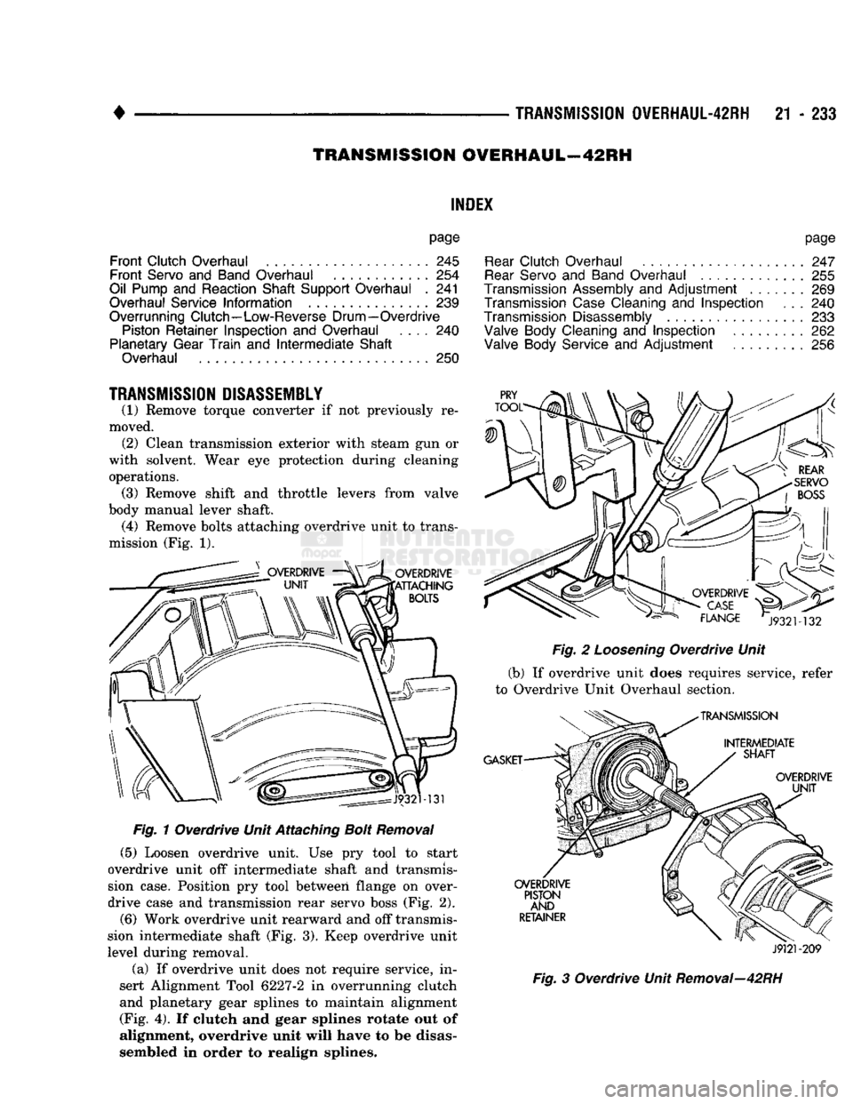
Remove bolts attaching overdrive unit
to
trans
mission (Fig. 1).
Fig.
1 Overdrive Unit Attaching
Bolt
Removal
(5)
Loosen overdrive unit.
Use pry
tool
to
start
overdrive unit
off
intermediate shaft
and
transmis
sion case. Position
pry
tool between flange
on
over
drive case and transmission rear servo boss (Fig. 2).
(6)
Work overdrive unit rearward and off transmis
sion intermediate shaft (Fig. 3). Keep overdrive unit
level during removal.
(a)
If
overdrive unit does
not
require service,
in
sert Alignment Tool
6227-2
in
overrunning clutch
and planetary gear splines
to
maintain alignment (Fig. 4).
If
clutch
and
gear splines
rotate out
of
alignment,
overdrive unit will have
to
be
disas
sembled
in
order
to
realign splines.
J9121-209
Fig.
3
Overdrive Unit Removal—42RH
Page 1289 of 1502
21
- 288
TRANSMISSION OVERHAUL-48RH
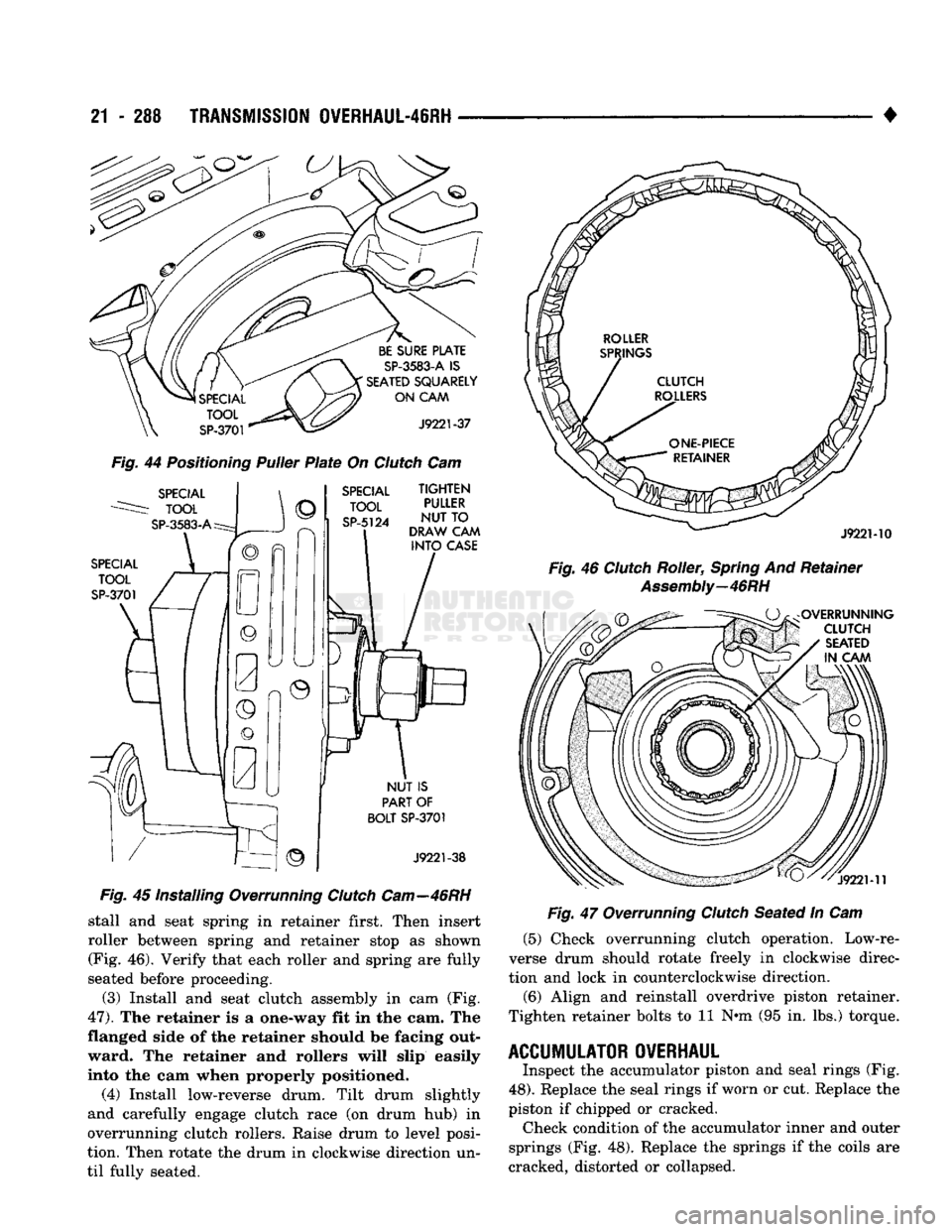
Fig.
44
Positioning
Puller
Plate
On
Clutch
Cam
Fig.
45 Installing Overrunning
Clutch
Cam—46RH
stall and seat spring in retainer first. Then insert
roller between spring and retainer stop as shown (Fig. 46). Verify that each roller and spring are fully
seated before proceeding.
(3) Install and seat clutch assembly in cam (Fig.
47).
The retainer is a one-way fit in the cam. The
flanged side of the retainer should be facing out ward. The retainer and rollers will slip easily
into the cam when properly positioned.
(4) Install low-reverse drum. Tilt drum slightly
and carefully engage clutch race (on drum hub) in
overrunning clutch rollers. Raise drum to level posi
tion. Then rotate the drum in clockwise direction un
til fully seated. •
Fig.
47 Overrunning
Clutch
Seated In Cam (5) Check overrunning clutch operation. Low-re
verse drum should rotate freely in clockwise direc
tion and lock in counterclockwise direction.
(6) Align and reinstall overdrive piston retainer.
Tighten retainer bolts to 11 N*m (95 in. lbs.) torque.
ACCUMULATOR OVERHAUL
Inspect the accumulator piston and seal rings (Fig.
48).
Replace the seal rings if worn or cut. Replace the
piston if chipped or cracked. Check condition of the accumulator inner and outer
springs (Fig. 48). Replace the springs if the coils are
cracked, distorted or collapsed.
Page 1343 of 1502
21
- 342
NP205 TRANSFER CASE
•
NP205
TRANSFER CASE
INDEX
page
General
Information
342
Recommended Lubricants
342
Service Diagnosis
342
Shift
Linkage
Adjustment
344
Speedometer Service
345
GENERAL
INFORMATION
The NP205 transfer case
is a
heavy duty, part-time
unit with constant mesh, helical gears.
The
gears
are
mounted
in a
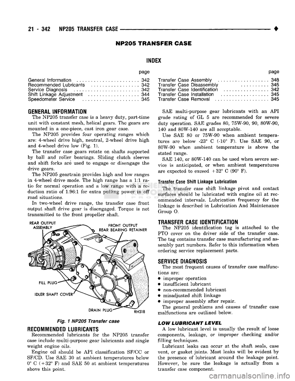
one-piece, cast iron gear case. The NP205 provides four operating ranges which
are:
4-wheel drive high, neutral, 2-wheel drive high
and 4-wheel drive
low (Fig. 1).
The transfer case gears rotate
on
shafts supported
by ball
and
roller bearings. Sliding clutch sleeves and shift forks
are
used
to
engage
or
disengage
the
drive gears. The NP205 geartrain provides high
and low
ranges
in 4-wheel drive mode.
The
high range
has a 1:1 ra
tio
for
normal operation
and a low
range with
a re
duction ratio
of 1.96:1 for
extra pulling power
in off
road situations. In two-wheel drive range,
the
transfer case front
output shaft drive gear
is
disengaged. Torque
is not
transmitted
to the
front propeller shaft.
Fig.
1
NP205 Transfer
case
RECOMMENDED
LUBRICANTS
Recommended lubricants
for the
NP205 transfer
case include multi-purpose gear lubricants
and
single
weight engine oils. Engine
oil
should
be API
classification SF/CC
or
SF/CD.
Use SAE 30 at
ambient temperatures below
0°
C
(
+
32°
F) and SAE 50 at
ambient temperatures
above this point.
page
Transfer
Case
Assembly
348
Transfer
Case
Disassembly
..........
345
Transfer
Case
Identification
342
Transfer
Case
Installation
345
Transfer
Case
Removal
345
SAE multi-purpose gear lubricants with
an API
grade rating
of GL 5 are
recommended
for
severe
duty operation.
SAE
grades
80,
75W-90,
90,
80W-90, 140
and
80W-140
are all
acceptable.
Use
SAE 80 or
75W-90 when ambient tempera
tures
are
below
-23° C (-10° F). Use SAE 90, or
80W-90 when ambient temperature
is
above
the
stated range.
SAE
140, or
80W-140
can be
used when severe ser
vice
is
anticipated,
or
when ambient temperatures are expected
to
exceed +32°
C (90° F).
Transfer Case Shift Linkage Lubrication
The transfer case shift linkage pivot
and
contact
surfaces should
be
lubricated with engine
oil at
rec
ommended intervals. Lubrication frequency
for the
linkage
is
described
in
Lubrication
And
Maintenance Group
O.
TRANSFER CASE
IDENTIFICATION
The NP205 identification
tag is
attached
to the
PTO cover
on the
driver side
of the
transfer case.
The
tag
contains transfer case manufacturing
and as
sembly part numbers. Refer
to
this information when
ordering service replacement parts.
SERVICE
DIAGNOSIS
The most frequent causes
of
transfer case malfunc
tions
are:
• improper operation
• insufficient lubricant
• non-recommended lubricant
• misadjusted shift linkage
• improper assembly after repair. The general problems
and
causes
of
transfer case
malfunctions
are
outlined below.
LOW LUBRICANT LEVEL
A
low
lubricant level
is
usually
the
result
of
loose
components, leakage,
or
improper checking and/or
filling techniques. Lubricant leaks
can
occur
at the
shaft seals, case
vent,
or
gasket joints. Most leaks will
be
evident
by
the presence
of
lubricant around
the
leakage point. However,
be
sure
the
leakage
is
actually from
a
transfer case component.
Page 1354 of 1502
•
NP241 TRANSFER
CASE
21 - 313
LOCK OIL RING SEAL
ADAPTER
(OVERDRIVE
ONLY)
SPEEDOMETER
PINION
GEAR
ADAPTER
O-RING
SPEEDOMETER
ADAPTER
RETAINER
DISTANCE
SENSOR
J9021-99
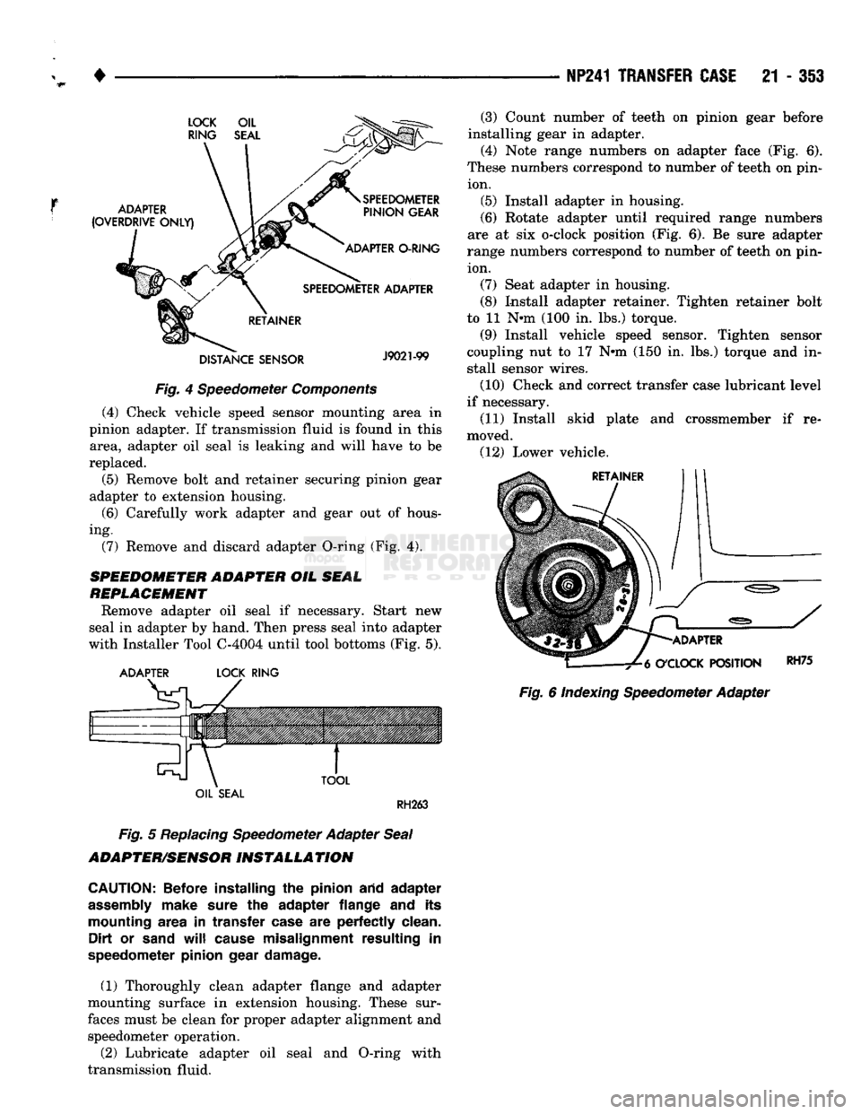
Fig.
4 Speedometer
Components
(4) Check vehicle speed sensor mounting area in
pinion adapter. If transmission fluid is found in this area, adapter oil seal is leaking and will have to be
replaced.
(5) Remove bolt and retainer securing pinion gear
adapter to extension housing.
(6)
Carefully work adapter and gear out of hous
ing. (7) Remove and discard adapter O-ring (Fig. 4).
SPEEDOMETER ADAPTER
OIL
SEAL
REPLACEMENT
Remove adapter oil seal if necessary. Start new
seal in adapter by hand. Then press seal into adapter
with Installer Tool C-4004 until tool bottoms (Fig. 5).
ADAPTER
LOCK
RING
TOOL
(3) Count number of teeth on pinion gear before
installing gear in adapter.
(4) Note range numbers on adapter face (Fig. 6).
These numbers correspond to number of teeth on pin ion. (5) Install adapter in housing.
(6)
Rotate adapter until required range numbers
are at six o-clock position (Fig. 6). Be sure adapter
range numbers correspond to number of teeth on pin ion. (7) Seat adapter in housing.
(8) Install adapter retainer. Tighten retainer bolt
to 11 N-m (100 in. lbs.) torque.
(9) Install vehicle speed sensor. Tighten sensor
coupling nut to 17 N-m (150 in. lbs.) torque and in
stall sensor wires.
(10) Check and correct transfer case lubricant level
if necessary.
(11) Install skid plate and crossmember if re
moved. (12) Lower vehicle.
ADAPTER
O'CLOCK
POSITION
Fig.
6 Indexing Speedometer Adapter
RH75
OIL
SEAL
RH263
Fig.
5
Replacing
Speedometer Adapter
Seal
ADAPTER/SENSOR
INSTALLATION
CAUTION:
Before installing
the
pinion arid adapter
assembly
make sure
the
adapter flange
and its
mounting area
in
transfer case
are
perfectly clean. Dirt
or
sand
will
cause misalignment resulting
in
speedometer pinion gear damage.
(1) Thoroughly clean adapter flange and adapter
mounting surface in extension housing. These sur
faces must be clean for proper adapter alignment and speedometer operation.
(2) Lubricate adapter oil seal and O-ring with
transmission fluid.
Page 1438 of 1502
•
• —• •
HEATING
AND AIR
CONDITIONING
24 - 1 CONTENTS
page
CLIMATE CONTROL SYSTEM
............. 21
REFRIGERANT SYSTEM SERWICE
COMPRESSOR
SERWICE
(SD-709)
......... 21
PROCEDURES
.............
DIAGNOSTIC PROCEDURES
3
TORQUE SPECIFICATIONS
GENERAL INFORMATION
1
page
. 17
. 31
GENERAL INFORMATION
HEATER SYSTEM
All models use a Blend-Air type heater. Outside air
enters the heater through the cowl opening and
passes through a plenum chamber to the heater core. Air intake openings must be kept free of snow, ice and other obstructions for the heater system to pick
up sufficient outside air. A temperature control door
in the heater housing directs incoming air through
the heater core and/or the heater core bypass. The amount of blend (heated and non-heated air) is deter
mined by the setting of the temperature lever on the
instrument panel. Direction of the blended air is con
trolled by the HEAT-DEFROST lever on the instru ment panel. The blower switch and resistor block controls the
speed of the blower motor. This in turn controls the
velocity of the air flow from the heater outlets. The resistor block consists of 2 helical wound wire
resistors connected to terminals which are mechani cally attached to a glass-filled phenolic board. This
assembly is bolted to the plenum. The blower switch controls the blower motor speed
by selectively connecting the resistors in series to the
blower motor.
A self-adjusting clip, on each of 2 control cables has
been incorporated to simplify cable adjustment. This clip snaps onto the control cable core wire and will slide along the wire under a specific load to provide
an automatic cable adjustment.
AIR
CONDITIONING
SYSTEM
Air intake openings must be kept free of snow, ice
and other obstructions for the air conditioning sys
tem to pick up sufficient outside air.
COMPONENTS
• COMPRESSOR-The seven piston SD-709 com
pressor is used on all vehicles. This compressor com
presses the low pressure refrigerant vapor into a high pressure, high temperature vapor. • CLUTCH PULLEY AND COIL-These are
mounted on the compressor, providing a convenient
way to drive it and disengage it in accordance to the cooling needs.
• CONDENSER-The condenser is located in front
of the radiator. Its function is to cool the hot, high
pressure refrigerant gas causing it to condense into
high pressure liquid refrigerant.
• FILTER-DRIER—The filter-drier is used to remove
any traces of moisture from the refrigerant system.
This component incorporates the sight glass and the
high pressure relief valve.
• SIGHT GLASS-The sight glass is provided as a
diagnostic tool to observe refrigerant flow and indi cate refrigerant level. It is located at the top of the
filter drier.
• HIGH -PRESSURE RELIEF VALVE-This is a safety device designed to open automatically if the
system pressure reaches a predetermined level. This
will prevent system component damage. • EXPANSION (H) VALVE-The expansion (H)
valve is used to meter refrigerant into the evaporator
in accordance with cooling requirements. • EVAPORATOR COIL-The evaporator coil is lo
cated in the A/C unit. Its function is to cool and de-
humidify the air before it enters the vehicle. • FREEZE CONTROL-The main function of freeze
control is to prevent water on the evaporator coil face
from freezing which restricts the airflow. An elec
tronic temperature cycling switch is located on the
refrigerant plumbing (suction line) near the H-Valve.
The switch turns the compressor ON-OFF depending
on the temperature in the suction line. The switch is a sealed, specially calibrated unit. If found defective,
the switch must be replaced. • REFRIGERANT LINES-These lines are needed
to carry the refrigerant between the various system components.
• CONDENSATE DRAIN TUBE-Condensation
which accumulates on the bottom of the evaporator
HEATING
AND AIR
CONDITIONING
Page 1444 of 1502
•
HEATING AND AIR CONDITIONING 24 - 7 AIR CONDITIONING SYSTEM
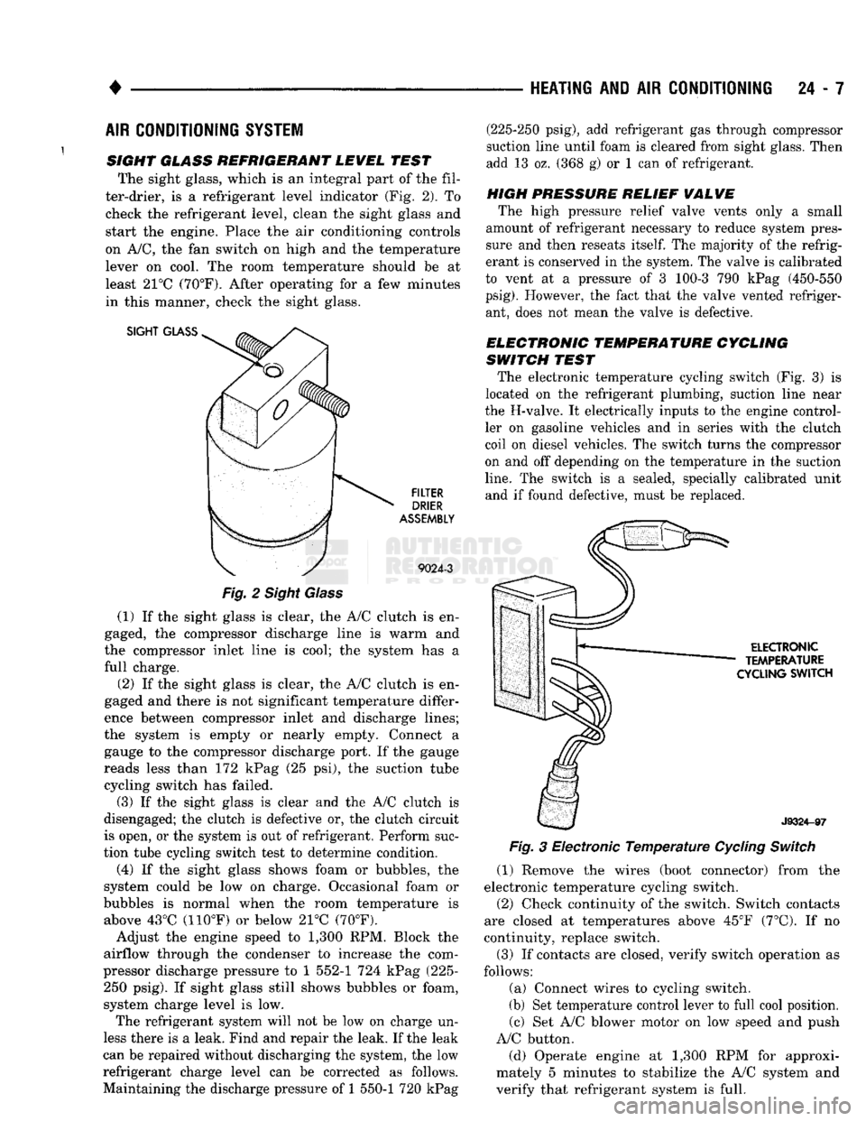
SIGHT GLASS REFRIGERANT LEWEL TEST The sight glass, which is an integral part of the fil
ter-drier, is a refrigerant level indicator (Fig. 2). To check the refrigerant level, clean the sight glass and
start the engine. Place the air conditioning controls
on A/C, the fan switch on high and the temperature lever on cool. The room temperature should be at
least 21°C (70°F). After operating for a few minutes
in this manner, check the sight glass.
SIGHT
GLASS
FILTER
DRIER
ASSEMBLY
9024-3
Fig.
2 Sight Glass
(1) If the sight glass is clear, the A/C clutch is en
gaged, the compressor discharge line is warm and
the compressor inlet line is cool; the system has a
full charge.
(2) If the sight glass is clear, the A/C clutch is en
gaged and there is not significant temperature differ
ence between compressor inlet and discharge lines;
the system is empty or nearly empty. Connect a gauge to the compressor discharge port. If the gauge
reads less than 172 kPag (25 psi), the suction tube cycling switch has failed.
(3) If the sight glass is clear and the A/C clutch is
disengaged; the clutch is defective or, the clutch circuit
is open, or the system is out of refrigerant. Perform suc
tion tube cycling switch test to determine condition.
(4) If the sight glass shows foam or bubbles, the
system could be low on charge. Occasional foam or
bubbles is normal when the room temperature is above 43°C (110°F) or below 21°C (70°F).
Adjust the engine speed to 1,300 RPM. Block the
airflow through the condenser to increase the com
pressor discharge pressure to 1 552-1 724 kPag (225- 250 psig). If sight glass still shows bubbles or foam,
system charge level is low. The refrigerant system will not be low on charge un
less there is a leak. Find and repair the leak. If the leak
can be repaired without discharging the system, the low
refrigerant charge level can be corrected as follows.
Maintaining the discharge pressure of 1 550-1 720 kPag (225-250 psig), add refrigerant gas through compressor
suction line until foam is cleared from sight glass. Then
add 13 oz. (368 g) or 1 can of refrigerant.
HIGH PRESSURE RELIEF
WALWE
The high pressure relief valve vents only a small
amount of refrigerant necessary to reduce system pres
sure and then reseats
itself.
The majority of the refrig
erant is conserved in the system. The valve is calibrated
to vent at a pressure of 3 100-3 790 kPag (450-550
psig).
However, the fact that the valve vented refriger ant, does not mean the valve is defective.
ELECTRONIC TEMPERATURE CYCLING
SWITCH TEST The electronic temperature cycling switch (Fig. 3) is
located on the refrigerant plumbing, suction line near
the H-valve. It electrically inputs to the engine control ler on gasoline vehicles and in series with the clutch
coil on diesel vehicles. The switch turns the compressor
on and off depending on the temperature in the suction
line.
The switch is a sealed, specially calibrated unit and if found defective, must be replaced.
ELECTRONIC
TEMPERATURE
CYCLING
SWITCH
J9324-97
Fig.
3 Electronic
Temperature
Cycling
Switch
(1) Remove the wires (boot connector) from the
electronic temperature cycling switch. (2) Check continuity of the switch. Switch contacts
are closed at temperatures above 45°F (7°C). If no
continuity, replace switch.
(3) If contacts are closed, verify switch operation as
follows:
(a) Connect wires to cycling switch.
(b) Set temperature control lever to full cool position. (c) Set A/C blower motor on low speed and push
A/C button.
(d) Operate engine at 1,300 RPM for approxi
mately 5 minutes to stabilize the A/C system and
verify that refrigerant system is full.
Page 1445 of 1502
24 - 8
HEATING
AND AIR
CONDITIONING
• (e) If compressor clutch cycles 3 to 10 times per
minute with temperature between 20°C-32°C (68°F-
90°F),
the cycling switch is normal. If the compressor
clutch fails to engage, check for continuity in the elec
trical circuit. Above 32°C (90°F) the compressor clutch
may be continuously engaged (non-cycling) due to the
high heat load. This condition is normal.
(4)
Refer to the Evaporator Heater Assembly for
the Removal/Installation procedures.
TESTING
THE
SYSTEM
FOR
LEAKS
If the air conditioning system is not cooling properly,
check that the refrigerant system is fully charged with
R-12.
Follow the procedures in the Sight Glass Refrig
erant Level Test section of this group.
If the refrigerant system is empty or low in refrig
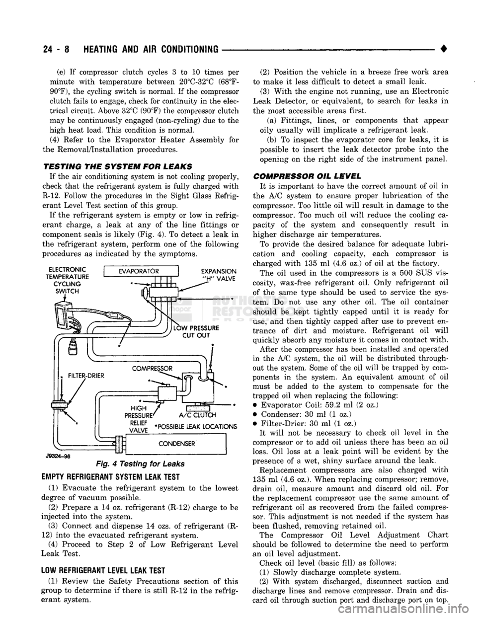
erant charge, a leak at any of the line fittings or
component seals is likely (Fig. 4). To detect a leak in
the refrigerant system, perform one of the following
procedures as indicated by the symptoms.
ELECTRONIC
TEMPERATURE CYCLING
SWITCH
EXPANSION
"H"
VALVE
J9324-96
Fig.
4 Testing for
Leaks
EMPTY REFRIGERANT SYSTEM LEAK TEST
(1) Evacuate the refrigerant system to the lowest
degree of vacuum possible.
(2) Prepare a 14 oz. refrigerant (R-12) charge to be
injected into the system. (3) Connect and dispense 14 ozs. of refrigerant (R-
12) into the evacuated refrigerant system, (4) Proceed to Step 2 of Low Refrigerant Level
Leak Test.
LOW REFRIGERANT LEVEL LEAK TEST
(1) Review the Safety Precautions section of this
group to determine if there is still R-12 in the refrig
erant system. (2) Position the vehicle in a breeze free work area
to make it less difficult to detect a small leak. (3) With the engine not running, use an Electronic
Leak Detector, or equivalent, to search for leaks in
the most accessible areas first.
(a) Fittings, lines, or components that appear
oily usually will implicate a refrigerant leak.
(b) To inspect the evaporator core for leaks, it is
possible to insert the leak detector probe into the opening on the right side of the instrument panel.
COMPRESSOR OIL LEVEL It is important to have the correct amount of oil in
the A/C system to ensure proper lubrication of the compressor. Too little oil will result in damage to the
compressor. Too much oil will reduce the cooling ca
pacity of the system and consequently result in
higher discharge air temperatures.
To provide the desired balance for adequate lubri
cation and cooling capacity, each compressor is
charged with 135 ml (4.6 oz.) of oil at the factory.
The oil used in the compressors is a 500 SUS vis
cosity, wax-free refrigerant oil. Only refrigerant oil of the same type should be used to service the sys
tem. Do not use any other oil. The oil container should be kept tightly capped until it is ready for
use,
and then tightly capped after use to prevent en
trance of dirt and moisture. Refrigerant oil will quickly absorb any moisture it comes in contact with.
After the compressor has been installed and operated
in the A/C system, the oil will be distributed through
out the system. Some of the oil will be trapped by com
ponents in the system. An equivalent amount of oil
must be added to the system to compensate for the
trapped oil when replacing the following: • Evaporator Coil: 59.2 ml (2 oz.)
• Condenser: 30 ml (1 oz.)
• Filter-Drier: 30 ml (1 oz.) It will not be necessary to check oil level in the
compressor or to add oil unless there has been an oil
loss.
Oil loss at a leak point will be evident by the
presence of a wet, shiny surface around the leak. Replacement compressors are also charged with
135 ml (4.6 oz.). When replacing compressor; remove,
drain oil, measure amount and discard old oil. For
the replacement compressor use the same amount of refrigerant oil as recovered from the failed compressor. This adjustment is not needed if the system has
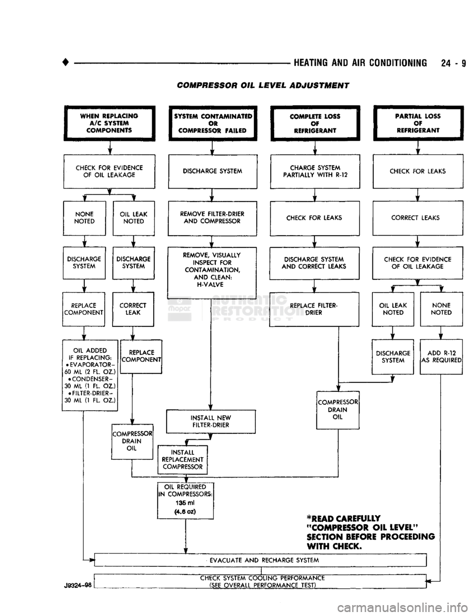
been flushed, removing retained oil. The Compressor Oil Level Adjustment Chart
should be followed to determine the need to perform
an oil level adjustment. Check oil level (basic fill) as follows: (1) Slowly discharge complete system.
(2) With system discharged, disconnect suction and
discharge lines and remove compressor. Drain and dis card oil through suction port and discharge port on top.
Page 1446 of 1502
•
HEATING AND AIR CONDITIONING 24 - 9 COMPRESSOR OIL LEVEL ADJUSTMENT
WHEN
REPLACING
I
A/C SYSTEM
I
COMPONENTS
1
CHECK
FOR
EVIDENCE
OF
OIL
LEAKAGE
1
SYSTEM
COI
I
c
I COMPRESS
OTAMINATEI^
m 1
Ot FAILED
1
1
f
DISCHARGE SYSTEM
I
COMPLE
1
c
I
REFRIG TE LOSS
I
f 1
ERANT
1
i f
CHARGE SYSTEM
PARTIALLY
WITH
R-12 1
PARTIA
1
c
•
REFRIG L LOSS
1
)¥ I
ERANT
1
f
CHECK
FOR
LEAKS
NONE
NOTED
OIL LEAK
NOTED
r
DISCHARGE
SYSTEM
DISCHARGE
SYSTEM
r ] r
REPLACE
COMPONENT CORRECT
LEAK
OIL ADDED
IF REPLACING:
•
EVAPORATOR-
60 ML (2 FL. OZ.)
•
CONDENSER-
30 ML (1 FL. OZ.) •
FILTER-DRIER-
30 ML (1 FL. OZ.)
REPLACE
COMPONENT
COMPRESSOR
DRAIN OIL REMOVE FILTER-DRIER
AND COMPRESSOR CHECK
FOR
LEAKS
REMOVE, VISUALLY
INSPECT
FOR
CONTAMINATION,
AND CLEAN:
H-VALVE
1
1
DISCHARGE SYSTEM
AND CORRECT LEAKS
1
f
REPLACE
FILTER-
DRIER
INSTALL
NEW
FILTER-DRIER
COMPRESSOR
DRAIN OIL
INSTALL
REPLACEMENT
COMPRESSOR
OIL REQUIRED
IN COMPRESSORS: 136 ml
(4.6
oz) CORRECT LEAKS
CHECK
FOR
EVIDENCE OF
OIL
LEAKAGE
OIL LEAK
NOTED
NONE
NOTED
DISCHARGE
SYSTEM ADD
R-12
AS
REQUIRED
*READ
CAREFULLY
"COMPRESSOR
OIL
LEVEL"
SECTION
BEFORE
PROCEEDING
WITH
CHECK.
EVACUATE
AND
RECHARGE SYSTEM
J9324-98
CHECK SYSTEM COOLING PERFORMANCE
(SEE
OVERALL PERFORMANCE
TEST)
Page 1454 of 1502
•
HEATING
AND
AIR
CONDITIONING
24-17 REFRIGERANT SYSTEM SERWICE PROCEDURES
INDEX
page
Charging
the
System
19
Correcting
Low
Refrigerant
Level
.............
20
Discharging
the
System
. 19
Evacuating
the
System
19
REFRIGERANT
SAFETY
PRECAUTIONS
WARNING: EXTREME CARE MUST
BE
TAKEN
TO
PREVENT
ANY LIQUID
REFRIGERANT FROM COM
ING
IN
CONTACT
WITH
THE
SKIN
AND
ESPE
CIALLY
THE
EYES.
ALWAYS WEAR SAFETY
GOGGLES WHEN SERVICING
ANY
PART
OF
THE
REFRIGERANT SYSTEM.
IF EYE
CONTACT
IS
MADE,
APPLY
A
FEW
DROPS
OF
MINERAL
OIL
TO
THE
EYES
AND
FLUSH
WITH
WATER
FOR
SEV
ERAL MINUTES.
SEEK
MEDICAL
ATTENTION
IMME
DIATELY.
The refrigerant used
in the air
conditioner system
is Refrigerant-12 (R-12).
R-12 is
nonexplosive, non
flammable, non-corrosive,
has
practically
no
odor
and
is heavier than
air.
Although
it is
classified
as a
safe
refrigerant, certain precautions must
be
observed
to
protect
the
parts involved
and the
person
who is
working
on the
unit. Liquid
R-12, at
normal atmo sphere pressures
and
temperatures, evaporates
so
quickly that
it has the
tendency
to
freeze anything
it
contacts.
WARNING:
TO
AVOID
A
DANGEROUS EXPLOSION,
NEVER
WELD
OR
STEAM CLEAN NEAR
AIR
CON
DITIONING
LINES
OR
COMPONENTS.
DO NOT
HEAT
R-12
ABOVE
52°C (125°F)
BECAUSE
THE
CAN
MAY
EXPLODE.
The
R-12 in the
system
is
always under pressure.
Because
the
system
is
tightly sealed, heat applied
to
any part could cause this pressure
to
build
up
excessively.
WARNING: LARGE AMOUNTS
OF
REFRIGERANT
RELEASED
IN A
CLOSED WORK AREA
WILL
DIS
PLACE
THE
OXYGEN
AND
CAUSE SUFFOCATION.
ALWAYS
MAINTAIN
GOOD
VENTILATION
SUR ROUNDING
THE
WORK AREA.
R-12
gas,
under normal conditions,
is
non-poison
ous.
The
discharge
of R-12 gas
near
an
open flame
page
Pressure Gauge
and
Manifold
Assembly
18
Refrigerant
. 17
Refrigerant
Leak Repair Procedure
20
Service Precautions
. 17
can produce
a
very poisonous
gas
called phosgene.
Phosgene
is
generated when
a
flame-type leak detec
tor
is
used.
CAUTION:
When charging
an A/C
system always
keep
the
tank
in an
upright position.
If the
tank
is
on
its
side
or
upside down,
liquid
refrigerant
will
enter
the
system
and may
damage
the
compressor.
In most instances, moderate heat
is
required
to
bring
the
pressure
of the
refrigerant above system
pressure when charging
or
adding refrigerant.
A
bucket
or
large
pan of hot
water,
not
over 52°C (125°F),
is all the
heat required
for
this purpose.
Do
not heat
the
refrigerant container with
a
blow torch
or
any
other means that would raise
the
temperature and pressure above this temperature.
CAUTION:
Do not
allow
liquid
refrigerant
to
touch
bright
metal.
Refrigerant will tarnish bright metal
and
chrome
surfaces. Avoid splashing
the
refrigerant
on any
sur
face.
Refrigerant
in
combination with moisture
is
very corrosive
and can
cause extensive damage
to all
metal surfaces.
RECYCLING
(R-12) refrigerant
is a
chloroflorocarbon
(CFC)
that
can contribute
to the
depletion
of the
ozone layer
in
the upper atmosphere. Harmful radiation from
the
sun
is
filtered
out by the
ozone.
To
assist
in
protect
ing
the
ozone layer, Chrysler Corporation recom
mends that
an
(R-12) refrigerant recycling device
that meets
SAE
standard
J1991 be
used. Contact
an
automotive service equipment supplier
for
refriger
ant recycling equipment that
is
available
in
your
area. Refer
to the
operating instructions provided
with
the
recycling equipment
for
proper operation.
SERVICE
PRECAUTIONS
Kinks
in the
refrigerant tubing
or
sharp bends
in
the refrigerant hose lines will greatly reduce
the ca
pacity
of the
entire system. High pressures
are
produced
in the
system when
it is
operating. Extreme
care must
be
exercised
to
make sure that
all
connec
tions
are
pressure tight. Dirt
and
moisture
can
enter
Page 1456 of 1502
•
HEATING
AND
AIR
CONDITIONING
24 - 19
Connect
the
compound gauge hose
to the
compres
sor suction service valve gauge port (low-side).
Connect
the
high pressure gauge hose
to the
dis
charge service valve gauge port (high-side). Purge
air
from
the
high side test hose
by
opening
the high side hand valve
on the
manifold
for 3 to 5
seconds.
The
center connection
on the
manifold must
be open.
Purge
air
from
the low
side test hose
by
opening
the
low
side hand valve
on the
manifold
for 3 to 5
seconds.
The
center connection
on the
manifold must
be open.
The
air
conditioning system
may be
operated with
the gauge manifold assembly connected
in
this man
ner.
The
gauges will indicate respective operative
pressures.
DISCHARGING
THE SYSTEM
Since
the air
conditioning refrigerant system
is
pressurized,
it
will
be
necessary
to
completely dis charge
the
system before replacing
any
refrigerant
components.
The
procedure
is as
follows: (1) Install gauge
set as
described under manifold
gauge
set
installation. Make sure
the
gauge
set
valves
are
closed before attaching
the
hoses
to the re
frigerant system. (2) Install
a
long hose
to the
manifold gauge
set
connector.
Run
this hose
to the oil
collector
can
near
the shop exhaust system. A good
oil
collector
can may be
made from
a
large
empty coffee
can
with
a
plastic
top.
Slit
the
plastic
top
in the
form
of a Y to
make
an
entrance
for the
refrigerant hose
and
exit
for the gas.
(3) Open
the
compressor discharge
and
suction line
pressure valves
and
discharge
the
refrigerant into
the
oil
collector
can.
Watch
to
make sure
the
hose does
not
blow
out of the
collector
can.
(4) When
the
system
has
been completely dis
charged, measure
the
amount
of oil
collected
in the
can.
The
amount
of oil
measured should
be
added
to
the refrigerant system before
it is
charged. Discard
the used
oil. Add new oil.
EVACUATING
THE SYSTEM
Whenever
the
system
has
been opened
to the
atmo
sphere,
it is
absolutely essential that
the
system
be
evacuated
to
remove
all the air and
moisture.
Air in
the refrigerant system causes high compressor dis charge pressures,
a
loss
in
system performance,
and
oxidation
of the
compressor
oil
into
gum and
varnish.
Moisture
in the
refrigerant system
can
cause
the ex
pansion valve
to
malfunction. Under certain condi
tions
it can
react with
the
refrigerant
to
form destructive acids.
It is
necessary
to
adhere
to the
fol
lowing procedure
to
keep
air and
moisture
out of the
system. (1) Connect
the
manifold gauge
set to the
compres
sor
and
long test hose from manifold gauge
set
center
connection
to
Vacuum Pump Tool C-4289. (2) Open both manifold gauge
set
valves.
(3) Start
the
vacuum pump
and
operate until
the
evaporator suction gauge registers
at
least
-88
kPag (26 inches
of
vacuum).
If at
least
-88
kPag
(26
inches
of vacuum) cannot
be
obtained, either
the
system
has
a leak
or the
vacuum pump
is
defective. Check
the
vacuum pump.
If the
pump proves
to be
functioning
properly,
the
system
has a
leak. Charge
the
system
with
1
pound
of
refrigerant. Locate
and
repair
all
leaks.
Discharge
the
refrigerant
and
evacuate
the
system.
(4) Continue
to
operate
the
pump
for at
least
5
minutes.
(5) Close manifold valves. Turn
off the
vacuum
pump
and
observe evaporator suction gauge
for 2
minutes.
The
vacuum level should remain constant.
If
the
vacuum level falls
off, the
system
has a
leak. Charge
the
system with
450 g (1
pound)
of
refriger
ant. Locate
and
repair
all
leaks. Discharge
the
sys
tem
and
repeat evacuation procedure.
CHARGING
THE
SYSTEM
The refrigerant system must have been evacuated
using
the
previous procedure before charging. Charge
using only
R-12
refrigerant.
R-12 is
available
in
bulk
tanks
or 437 g (14 oz.)
cans. The special refrigerant dispensing manifold per
mits charging
3
cans
of
refrigerant
at a
time. When
using disposable cans
of
this type, carefully follow
the
can
manufacturers instructions.
WARNING: NEVER USE THESE CANS
TO
CHARGE
INTO
THE
HIGH
PRESSURE SIDE
OF
THE
SYSTEM
(COMPRESSOR
DISCHARGE PORT)
OR
INTO
A
SYSTEM
THAT
IS AT
HIGH
TEMPERATURE.
THE
HIGH
SYSTEM PRESSURES COULD
BE
TRANS
FERRED
INTO
THE
CHARGING
CAN
CAUSING
IT
TO EXPLODE.
Keep
the
refrigerant manifold valves capped when
not
in use.
Keep
a
supply
of
extra refrigerant-can-to
refrigerant-manifold gaskets
on
hand
so the
gaskets can
be
replaced periodically. This will insure
a
good
seal without excessive tightening
of the can or the
manifold nuts.
(1) Attach center hose from manifold gauge
set to
refrigerant dispensing manifold. Turn refrigerant manifold valves completely counterclockwise
so
they are fully open. Remove protective caps from refriger
ant manifold.
(2) Screw refrigerant cans into manifold.
Be
sure
manifold-to-can gasket
is in
place
and in
good condi
tion. Tighten
can and
manifold nuts
to 9.5 N»m (7 ft.
lbs.) torque.