oil level DODGE TRUCK 1993 Service Service Manual
[x] Cancel search | Manufacturer: DODGE, Model Year: 1993, Model line: TRUCK, Model: DODGE TRUCK 1993Pages: 1502, PDF Size: 80.97 MB
Page 669 of 1502
9
- 64 5.2L
ENGINE
• into the top of the dowel. This will allow easier in
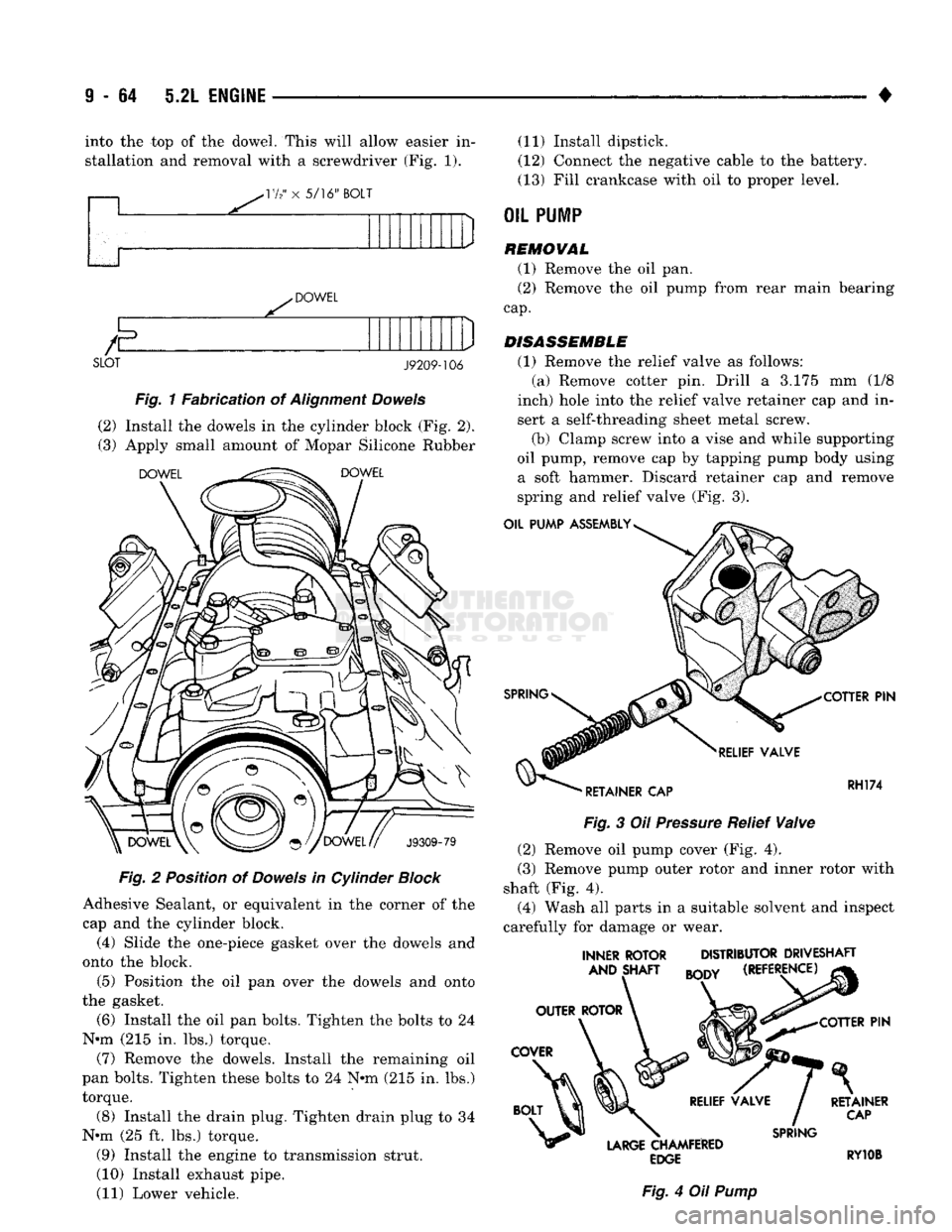
stallation and removal with a screwdriver (Fig. 1).
VI2' x 5/16"
BOLT
DOWEL SLOT
J9209-106
Fig. 1 Fabrication of Alignment Dowels
(2) Install the dowels in the cylinder block (Fig. 2). (3) Apply small amount of Mopar Silicone Rubber
DOWEL DOWEL
J9309-79
Fig. 2 Position of Dowels in Cylinder Block
Adhesive Sealant, or equivalent in the corner of the cap and the cylinder block. (4) Slide the one-piece gasket over the dowels and
onto the block.
(5) Position the oil pan over the dowels and onto
the gasket.
(6) Install the oil pan bolts. Tighten the bolts to 24
N*m (215 in. lbs.) torque.
(7) Remove the dowels. Install the remaining oil
pan bolts. Tighten these bolts to 24 N«m (215 in. lbs.)
torque. (8) Install the drain plug. Tighten drain plug to 34
N«m (25 ft. lbs.) torque.
(9) Install the engine to transmission strut.
(10) Install exhaust pipe.
(11) Lower vehicle. (11) Install dipstick.
(12) Connect the negative cable to the battery.
(13) Fill crankcase with oil to proper level.
OIL
PUMP
REMOVAL
(1) Remove the oil pan.
(2) Remove the oil pump from rear main bearing
cap.
DISASSEMBLE
(1) Remove the relief valve as follows: (a) Remove cotter pin. Drill a 3.175 mm (1/8
inch) hole into the relief valve retainer cap and in sert a self-threading sheet metal screw.
(b) Clamp screw into a vise and while supporting
oil pump, remove cap by tapping pump body using a soft hammer. Discard retainer cap and remove
spring and relief valve (Fig. 3).
OIL PUMP
ASSEMBLY
SPRING
RELIEF
VALVE
'
RETAINER CAP COTTER
PIN
RH174
Fig.
3 Oil
Pressure
Relief
Valve
(2) Remove oil pump cover (Fig. 4).
(3) Remove pump outer rotor and inner rotor with
shaft (Fig. 4). (4) Wash all parts in a suitable solvent and inspect
carefully for damage or wear.
INNER ROTOR DISTRIBUTOR DRIVESHAFT
AND SHAFT
mm
(REFERENCE)
COTTER
PIN
LARGE
CHAMFERED
EDGE
Fig.
4 Oil
Pump
SPRING
RETAINER
CAP
RY10B
Page 692 of 1502
•
5.9L ENGINE
9 - 87 (6) With air hose attached to an adapter installed
in No.l spark plug hole, apply 620-689 kPa (90-100
psi) air pressure.
(7) Using Valve Spring Compressor Tool
MD-998772A, compress valve spring and remove re
tainer valve locks and valve spring.
(8) Install seals on the exhaust valve stem and po
sition down against valve guides.
(9) The intake valve stem seals should be pushed
firmly and squarely over the valve guide using the
valve stem as a guide. DO NOT force seal against
top of guide. When installing the valve retainer
locks,
compress the spring only enough to install the
locks.
(10) Follow the same procedure on the remaining 7
cylinders using the firing sequence 1-8-4-3-6-5-7-2.
Make sure piston in cylinder is at TDC on the valve spring that is being removed. (11) Remove adapter from the No.l spark plug
hole.
(12) Install rocker arms.
(13) Install covers and coil wire to distributor.
(14) Install air cleaner.
(15) Road test vehicle.
HYDRAULIC
TAPPETS
Before disassembling any part of the engine to cor
rect tappet noise, check the oil pressure. If vehicle
has no oil pressure gauge, Install a reliable gauge at
the pressure sending unit. The pressure should be be
tween 207-552 kPa (30-80 psi) at 3,000 RPM. Check the oil level after the engine reaches normal
operating temperature. Allow 5 minutes to stabilize
oil level, check dipstick. The oil level in the pan should never be above the
FULL mark or below the ADD OIL mark on dipstick.
Either of these 2 conditions could be responsible for
noisy tappets.
OIL LEVEL
HIGH
If oil level Is above the FULL mark, It is possible
for the connecting rods to dip into the oil. With the engine running this condition could create foam in
the oil pan. Foam in oil pan would be fed to the hy
draulic tappets by the oil pump causing them to lose
length and allow valves to seat noisily.
LOW
Low oil level may allow oil pump to take in air.
When air is fed to the tappets, causes them to lose length and allows valves to seat noisily. Any leaks
on intake side of oil pump through which air can be
drawn will create the same tappet action. When tap
pet noise is due to aeration, it may be intermittent or constant, and usually more than 1 tappet will be
noisy. When oil level and leaks have been corrected, engine should be operated at fast idle for sufficient
time.
This allows all of the air inside of the tappets
to be bled out.
TAPPET NOISE DIAGNOSIS
(1) To determine source of tappet noise, operate en
gine at idle with cylinder head covers removed. (2) Feel each valve spring or rocker arm to detect
noisy tappet. The noisy tappet will cause the affected
spring and/or rocker arm to vibrate or feel rough in
operation.
Worn valve guides or cocked springs are some
times mistaken for
noisy tappets.
If such is the
case,
noise may be dampened by applying side
thrust on the
valve
spring. If noise is not appre ciably reduced, it can be assumed the noise Is in
the tappet. Inspect the rocker arm push rod sockets and
push
rod ends for wear.
(3) Valve tappet noise ranges from light noise to a
heavy click. A light noise is usually caused by exces
sive leak-down around the unit plunger or by the
plunger partially sticking in the tappet body cylin der. The tappet should be replaced. A heavy click is
caused by a tappet check valve not seating or by for
eign particles becoming wedged between the plunger and the tappet body. This will cause the plunger to
stick in the down position. This heavy click will be
accompanied by excessive clearance between the
valve stem and rocker arm as valve closes. In either
case,
tappet assembly should be removed for inspec
tion and cleaning.
The valve train generates a noise very much like a
light tappet noise during normal operation. Care
must be taken to ensure that tappets are making the
noise. In general, if more than one tappet seems to
be noisy, its probably not the tappets.
REMOVAL
(1) Remove the air cleaner.
(2) Remove cylinder head cover.
(3) Remove rocker assembly and push rods. Iden
tify push rods to ensure Installation in original loca
tion.
(4) Remove Intake manifold.
(5) Remove yoke retainer and aligning yokes.
(6) Slide Hydraulic Tappet Remover/Installer Tool
C-4129-A through opening in cylinder head and seat
tool firmly in the head of tappet.
(7) Pull tappet out of bore with a twisting motion.
If all tappets are to be removed, identify tappets to ensure installation in original location.
(8) If the tappet or bore in cylinder block is scored,
scuffed, or shows signs of sticking, ream the bore to
next oversize. Replace with oversize tappet.
Page 699 of 1502
-17
" x
5/16" BOLT
DOWEL
E
SLOT J9209-106
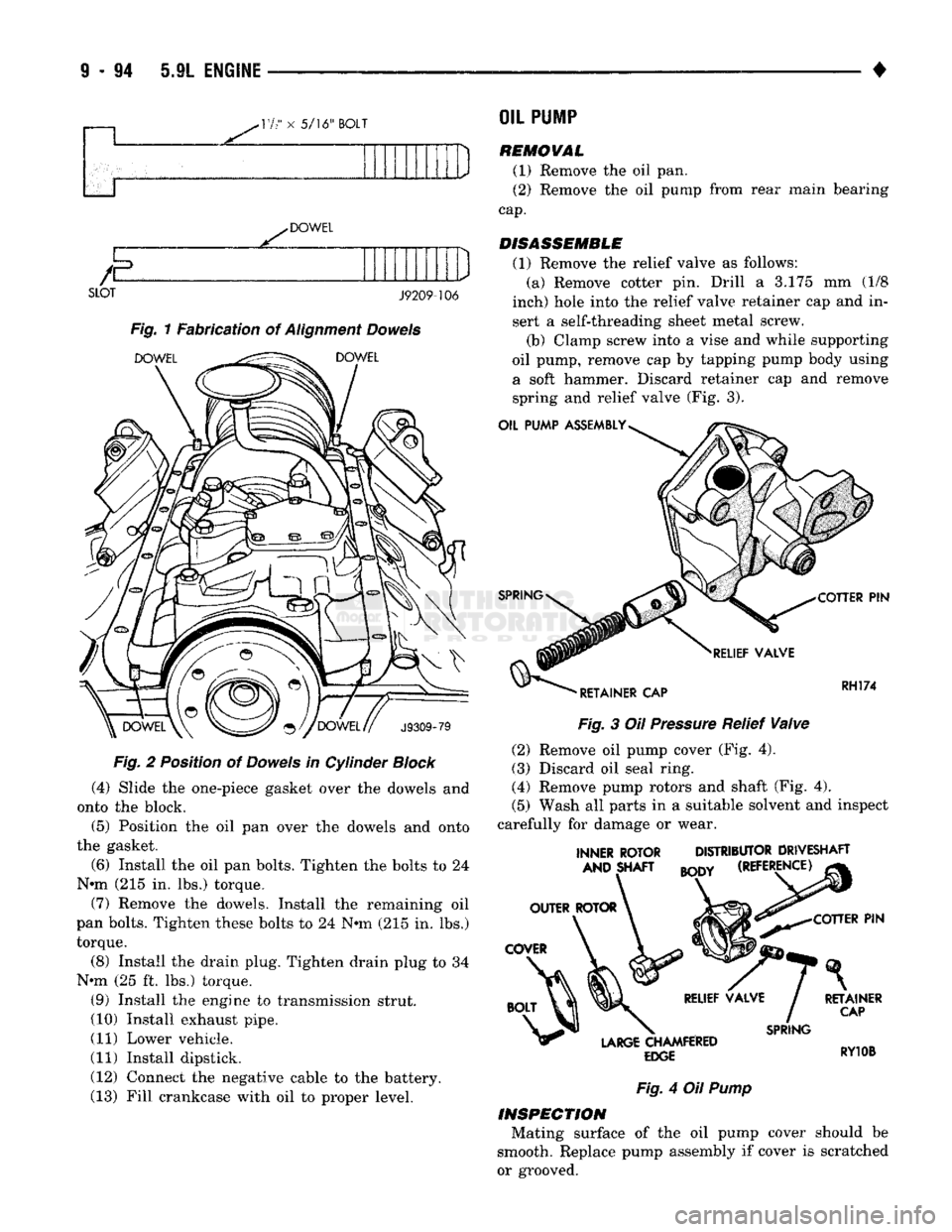
Fig. 1 Fabrication of Alignment Dowels
DOWEL
^^^^
DOWEL
J9309-79
F/g.
2 Position of Dowels in Cylinder
Block
(4) Slide the one-piece gasket over the dowels and
onto the block.
(5) Position the oil pan over the dowels and onto
the gasket.
(6) Install the oil pan bolts. Tighten the bolts to 24
N*m (215 in. lbs.) torque.
(7) Remove the dowels. Install the remaining oil
pan bolts. Tighten these bolts to 24 Nmi (215 in. lbs.) torque.
(8) Install the drain plug. Tighten drain plug to 34
N-m (25 ft. lbs.) torque. (9) Install the engine to transmission strut.
(10) Install exhaust pipe.
(11) Lower vehicle.
(11) Install dipstick.
(12) Connect the negative cable to the battery.
(13) Fill crankcase with oil to proper level.
OIL
PU1P
REMOVAL
(1) Remove the oil pan.
(2) Remove the oil pump from rear main bearing
cap.
DISASSEMBLE
(1) Remove the relief valve as follows: (a) Remove cotter pin. Drill a 3.175 mm (1/8
inch) hole into the relief valve retainer cap and in
sert a self-threading sheet metal screw.
(b) Clamp screw into a vise and while supporting
oil pump, remove cap by tapping pump body using a soft hammer. Discard retainer cap and remove spring and relief valve (Fig. 3).
OIL PUMP ASSEMBLY
SPRING
COTTER
PIN
RELIEF VALVE
'
RETAINER CAP RH174
Fig.
3 Oil
Pressure
Relief
Valve
(2) Remove oil pump cover (Fig. 4).
(3) Discard oil seal ring.
(4) Remove pump rotors and shaft (Fig. 4).
(5) Wash all parts in a suitable solvent and inspect
carefully for damage or wear.
INNER ROTOR AND SHAFT DISTRIBUTOR DRIVESHAFT
BODY
(REFERENCE) COTTER
PIN
LARGE
CHAMFERED
EDGE
SPRING
RETAINER
CAP
RY10B
Fig.
4 Oil
Pump
INSPECTION
Mating surface of the oil pump cover should be
smooth. Replace pump assembly If cover is scratched
or grooved.
Page 717 of 1502
9
- 112 5.9L
(DIESEL)
ENGINE
• (5) Position the engine in the chassis and install
the through bolt. Tighten the through bolt nut to 41
N-m (30 ft. lbs.) torque. (6) Make sure the lifting brackets are mounted
with the eye down. (7) Remove the covers or tape covering the engine
openings. (8) Connect the fuel lines to the lift pump and fuel
return.
(9) Connect all electrical connections.
(10) Connect the power steering lines.
(11) Raise and support the vehicle on a hoist.
(12) AUTOMATIC TRANSMISSION:
CAUTION:
If new
flex
plate is installed, remove
flashing
from the engine
back
plate at the 5 and 7
o'clock
positions.
(a) Rotate converter until alignment mark on the
converter is aligned with mark on drive plate.
Off
set holes in plate are next to 1/8 inch hole in inner
circle of drive plate.
(b) Install bell housing bolts. Tighten the bolts to
41 N-m (30 ft. lbs.) torque. (c) With the torque converter plate aligned to the
torque converter, install and tighten the bolts to 31 N-m (270 in. lbs.) torque. (d) Install the converter housing access plate.
(e) Remove the transmission support.
(13) MANUAL TRANSMISSION:
Refer to Group 21, Transmissions for the G360
Manual Transmission Installation procedure. (14) Connect the ground cable and tighten the nut
to 22 N-m (16 ft. lbs.) torque. Connect the solenoid cable and tighten the nut to 5 N-m (44 in. lbs.)
torque.
(15) Connect the transmission cooler lines.
(16) Install the exhaust pipe to the exhaust sys
tem.
(17) Lower the vehicle.
(18) Install the A/C compressor and tighten the
bolts to 47 N-m (35 ft. lbs.) torque. If removed, con nect the clutch electrical wire.
(19) Install the generator. Tighten the upper
mounting bolts to 24 N-m (18 ft. lbs.) torque. Now
tighten the lower mounting bolts to 43 N-m (32 ft. lbs.) torque. Connect all wires.
(20) Install the radiator, fan/fan clutch assembly
and fan shroud (refer to Group 7, Cooling Systems
for the proper procedures). Connect the radiator
hoses.
(21) Position the intercooler inlet duct to the tur
bocharger and the intercooler. With the clamps in po sition, tighten the clamp nut to 8 N-m (72 in. lbs.)
torque. (22) Position the intercooler outlet duct to the air
inlet housing and the intercooler. With the clamps in
position, tighten the clamp nut to 8 N-m (72 in. lbs.)
torque.
(23) Connect the air intake tube to the turbo
charger inlet flange and the air cleaner housing.
Tighten the clamps to 8 N-m (72 in. lbs.) torque. (24) Install the exhaust pipe to the turbocharger.
Tighten the steady rest clamp to 8 N-m (72 in. lbs.) torque.
(25) Make sure the air intake and exhaust pipe
connections are tight and free of leaks.
(26) Fill the engine with the required amount of
clean engine lubricating oil (refer to Group 0, Lubri cation and Maintenance).
(27) Fill the cooling system with a mixture of 50%
water and 50% ethylene-glycol base antifreeze (refer Group 7, Cooling System for the proper procedure).
(28) Install the battery and connect the battery ca
bles.
(29) Check the oil level after the engine has run
for 2 or 3 minutes. Oil held in the oil filter and oil passages will cause the oil level in the pan to be lower.
(30) Operate the engine at idle for 5 to 10 minutes
and check for leaks and loose parts.
ROCKER LEVERS
/
POSH
RODS
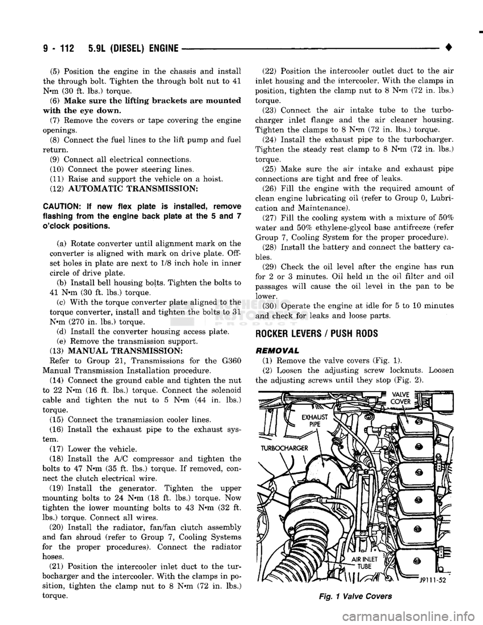
REMOVAL (1) Remove the valve covers (Fig. 1). (2) Loosen the adjusting screw locknuts. Loosen
the adjusting screws until they stop (Fig. 2).
Page 739 of 1502
9
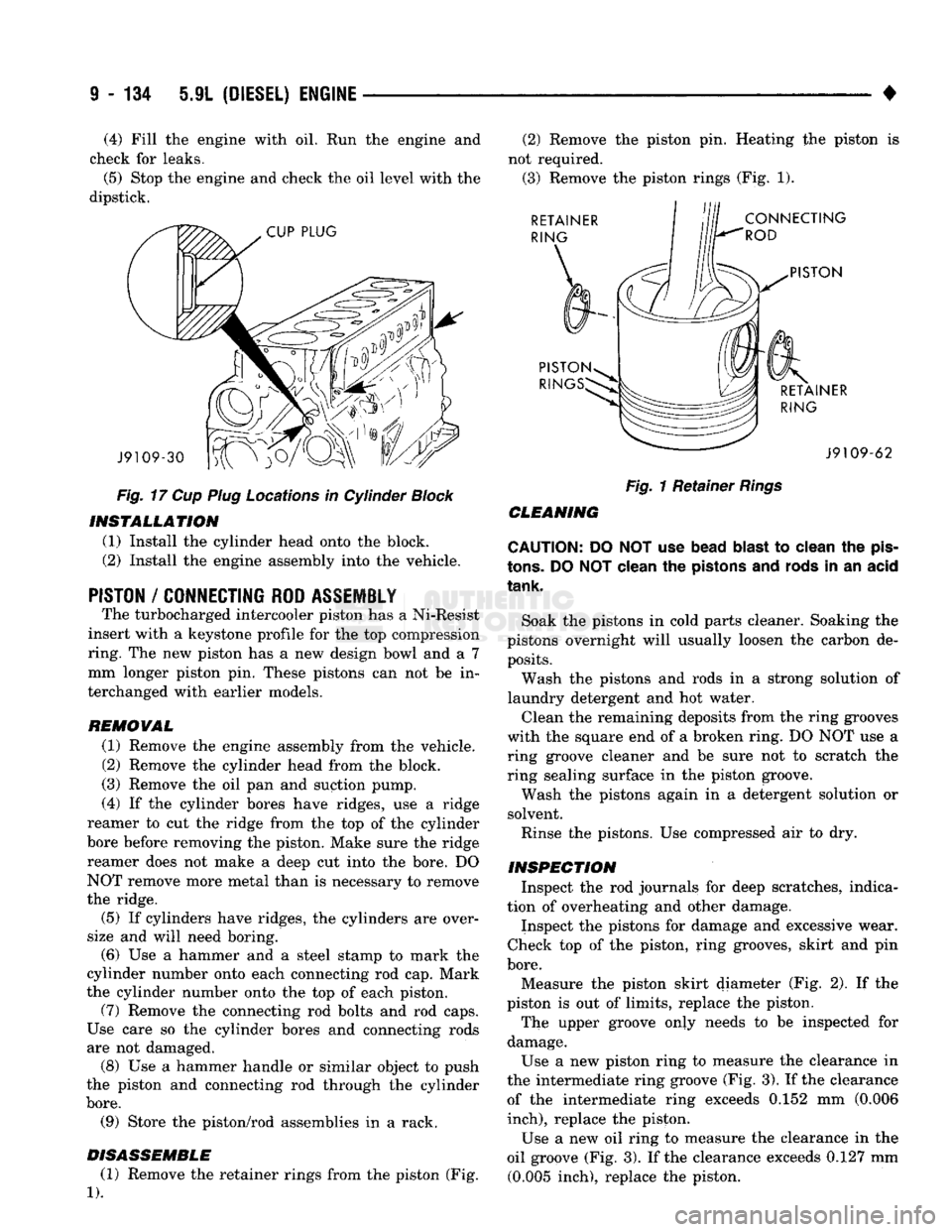
- 134 5.9L
(DIESEL) ENGINE
• (4) Fill the engine with oil. Run the engine and
check for leaks.
(5) Stop the engine and check the oil level with the
dipstick.
CUP
PLUG
J9109-30
Fig.
17 Cup Plug Locations in Cylinder Block INSTALLATION
(1) Install the cylinder head onto the block.
(2) Install the engine assembly into the vehicle.
PISTON
/
CONNECTING ROD ASSEMBLY
The turbocharged intercooler piston has a Ni-Resist
insert with a keystone profile for the top compression
ring. The new piston has a new design bowl and a 7 mm longer piston pin. These pistons can not be in
terchanged with earlier models.
REMOVAL (1) Remove the engine assembly from the vehicle.
(2) Remove the cylinder head from the block.
(3) Remove the oil pan and suction pump.
(4) If the cylinder bores have ridges, use a ridge
reamer to cut the ridge from the top of the cylinder
bore before removing the piston. Make sure the ridge reamer does not make a deep cut into the bore. DO
NOT remove more metal than is necessary to remove
the ridge.
(5) If cylinders have ridges, the cylinders are over
size and will need boring. (6) Use a hammer and a steel stamp to mark the
cylinder number onto each connecting rod cap. Mark
the cylinder number onto the top of each piston. (7) Remove the connecting rod bolts and rod caps.
Use care so the cylinder bores and connecting rods
are not damaged. (8) Use a hammer handle or similar object to push
the piston and connecting rod through the cylinder
bore.
(9) Store the piston/rod assemblies in a rack.
DISASSEMBLE (1) Remove the retainer rings from the piston (Fig.
1).
(2) Remove the piston pin. Heating the piston is
not required. (3) Remove the piston rings (Fig. 1). RETAINER
RING
CONNECTING
ROD
PISTON
PISTON RIN RETAINER
RING J9109-62
Fig.
1 Retainer
Rings
CLEANING
CAUTION: DO NOT use bead
blast
to clean the
pis
tons.
DO
NOT
clean the pistons and rods in an acid
tank.
Soak the pistons in cold parts cleaner. Soaking the
pistons overnight will usually loosen the carbon de posits.
Wash the pistons and rods in a strong solution of
laundry detergent and hot water.
Clean the remaining deposits from the ring grooves
with the square end of a broken ring. DO NOT use a
ring groove cleaner and be sure not to scratch the
ring sealing surface in the piston groove.
Wash the pistons again in a detergent solution or
solvent.
Rinse the pistons. Use compressed air to dry.
INSPECTION Inspect the rod journals for deep scratches, indica
tion of overheating and other damage.
Inspect the pistons for damage and excessive wear.
Check top of the piston, ring grooves, skirt and pin
bore.
Measure the piston skirt diameter (Fig. 2). If the
piston is out of limits, replace the piston.
The upper groove only needs to be inspected for
damage.
Use a new piston ring to measure the clearance in
the intermediate ring groove (Fig. 3). If the clearance of the intermediate ring exceeds 0.152 mm (0.006
inch),
replace the piston.
Use a new oil ring to measure the clearance in the
oil groove (Fig. 3). If the clearance exceeds 0.127 mm (0.005 inch), replace the piston.
Page 747 of 1502
9
- 142 5.9L
(DIESEL)
ENGINE
•
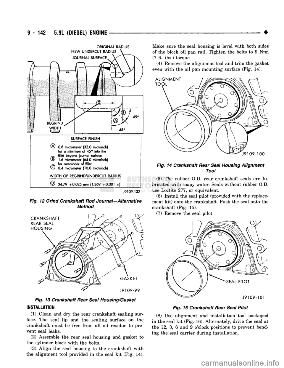
ORIGINAL
RADIUS
SURFACE
FINISH
®
0.3
micrometer
(32.0
microinch)
for a
minimum
of
45° into the
^ fillet
beyond
journal
surface
v§/
1.6
micrometer
(64.0
microinch)
^ for
remainder
of
fillet
v£)
0.4
micrometer
(16.0
microinch)
WIDTH OF REGRIND/UNDERCUT RADIUS
©
34.79
±
0.025
mm
(1.369
±0.001 in)
J9109-132
Fig.
12
Grind
Crankshaft Rod Journal—Alternative
Method
Fig.
13 Crankshaft Rear
Seal
Housing/Gasket
INSTALLATION
(1) Clean and dry the rear crankshaft sealing sur
face.
The seal lip and the sealing surface on the
crankshaft must be free from all oil residue to pre vent seal leaks.
(2) Assemble the rear seal housing and gasket to
the cylinder block with the bolts.
(3) Align the seal housing to the crankshaft with
the alignment tool provided in the seal kit (Fig. 14). Make sure the seal housing is level with both sides
of the block oil pan rail. Tighten the bolts to 9 N*m
(7 ft. lbs.) torque.
(4) Remove the alignment tool and trim the gasket
even with the oil pan mounting surface (Fig. 14).
Fig.
14 Crankshaft Rear
Seal
Housing
Alignment
Tool
(5) The rubber O.D. rear crankshaft seals are lu
bricated with soapy water. Seals without rubber O.D. use Loctite 277, or equivalent.
(6) Install the seal pilot (provided with the replace
ment kit) onto the crankshaft. Push the seal onto the
crankshaft (Fig. 15).
(7) Remove the seal pilot.
Fig.
15 Crankshaft Rear
Seal
Pilot
(8) Use alignment and installation tool packaged
in the seal kit (Fig. 16). Alternately, drive the seal at
the 12, 3, 6 and 9 o'clock positions to prevent bend ing the seal carrier during installation.
Page 749 of 1502
9 - 146 5.9L (DIESEL) ENGINE
•
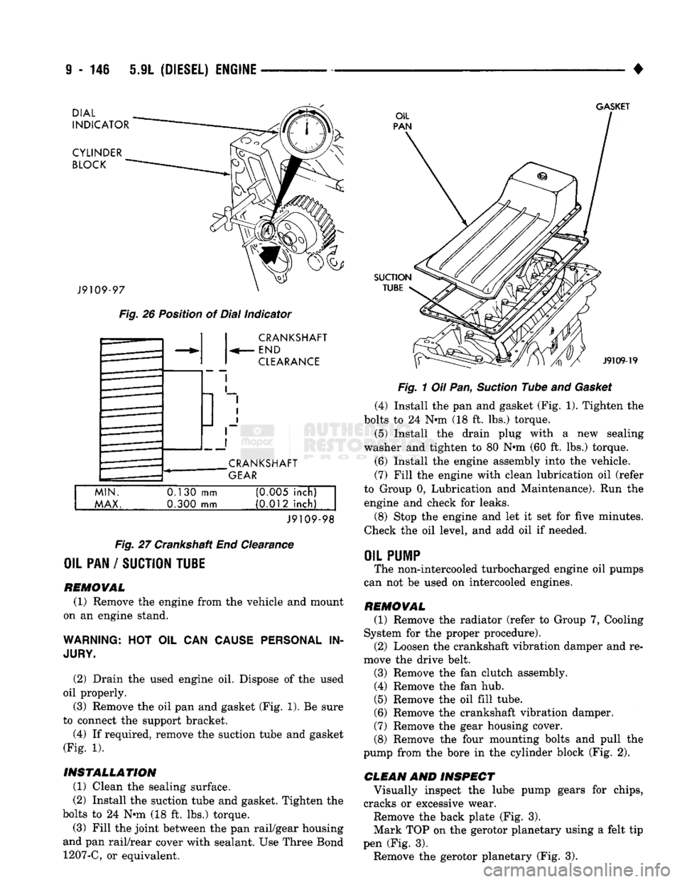
DIAL
INDICATOR
CYLINDER BLOCK
GASKET
J9109-97
Fig.
26 Position of Dial Indicator CRANKSHAFT
END
CLEARANCE
CRANKSHAFT
GEAR
MIN.
MAX.
0.130
mm
0.300 mm (0M5 inch)
(0.012 inch)
J9109-98
Fig.
27 Crankshaft End Clearance
OIL PAN / SUCTION TU1E
REMOVAL (1) Remove the engine from the vehicle and mount
on an engine stand.
WARNING:
HOT OIL CAN
CAUSE PERSONAL
IN
JURY.
(2) Drain the used engine oil. Dispose of the used
oil properly. (3) Remove the oil pan and gasket (Fig. 1). Be sure
to connect the support bracket.
(4) If required, remove the suction tube and gasket
(Fig. 1).
INSTALLATION (1) Clean the sealing surface.
(2) Install the suction tube and gasket. Tighten the
bolts to 24 Nin (18 ft. lbs.) torque.
(3) Fill the joint between the pan rail/gear housing
and pan rail/rear cover with sealant. Use Three Bond 1207-C, or equivalent.
SUCTION
TUBE
J9109-19
Fig.
1 Oil Pan,
Suction
Tube and
Gasket
(4) Install the pan and gasket (Fig. 1). Tighten the
bolts to 24 N-m (18 ft. lbs.) torque.
(5) Install the drain plug with
a
new sealing
washer and tighten to 80 Nnn (60 ft. lbs.) torque.
(6) Install the engine assembly into the vehicle.
(7) Fill the engine with clean lubrication oil (refer
to Group 0, Lubrication and Maintenance). Run the engine and check for leaks.
(8) Stop the engine and let it set for five minutes.
Check the oil level, and add oil if needed.
OIL
PUMP
The non-intercooled turbocharged engine oil pumps
can not be used on intercooled engines.
REMOVAL (1) Remove the radiator (refer to Group 7, Cooling
System for the proper procedure). (2) Loosen the crankshaft vibration damper and re
move the drive belt.
(3) Remove the fan clutch assembly. (4) Remove the fan hub.
(5) Remove the oil fill tube.
(6) Remove the crankshaft vibration damper.
(7) Remove the gear housing cover.
(8) Remove the four mounting bolts and pull the
pump from the bore in the cylinder block (Fig. 2).
CLEAN AND INSPECT Visually inspect the lube pump gears for chips,
cracks or excessive wear.
Remove the back plate (Fig. 3).
Mark TOP on the gerotor planetary using a felt tip
pen (Fig. 3). Remove the gerotor planetary (Fig. 3).
Page 751 of 1502
9
- 148 5.9L
(DIESEL) ENGINE
• Make sure the idler gear pin is installed in the lo
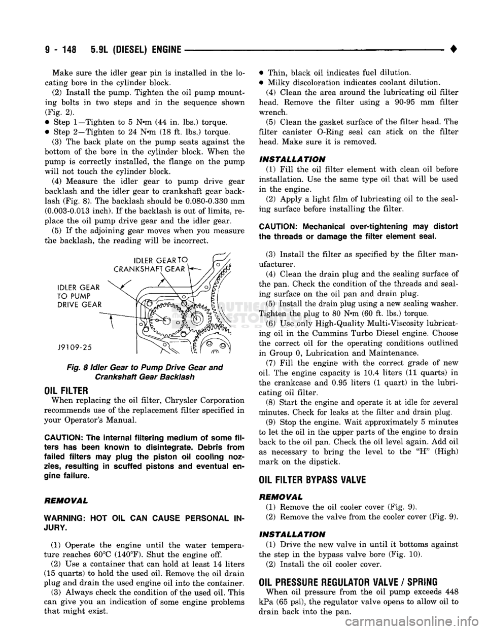
cating bore in the cylinder block. (2) Install the pump. Tighten the oil pump mount
ing bolts in two steps and in the sequence shown (Fig. 2).
• Step
1—Tighten
to 5 N«m (44 in. lbs.) torque.
• Step 2-Tighten to 24 N*m (18 ft. lbs.) torque. (3) The back plate on the pump seats against the
bottom of the bore in the cylinder block. When the
pump is correctly installed, the flange on the pump will not touch the cylinder block.
(4) Measure the idler gear to pump drive gear
backlash and the idler gear to crankshaft gear back lash (Fig. 8). The backlash should be 0.080-0.330 mm (0.003-0.013 inch). If the backlash is out of limits, re
place the oil pump drive gear and the idler gear.
(5) If the adjoining gear moves when you measure
the backlash, the reading will be incorrect.
Fig.
8
idler
Gear to
Pump
Drive Gear and Crankshaft Gear
Backlash
OIL FILTER
When replacing the oil filter, Chrysler Corporation
recommends use of the replacement filter specified in
your Operator's Manual.
CAUTION:
The
internal filtering medium
of
some
fil
ters
has
been known
to
disintegrate. Debris from
failed filters
may
plug
the
piston
oil
cooling noz
zles,
resulting
in
scuffed pistons
and
eventual
en
gine
failure.
REMOVAL
WARNING:
HOT OIL CAN
CAUSE PERSONAL
IN
JURY.
(1) Operate the engine until the water tempera
ture reaches 60°C (140°F). Shut the engine off.
(2) Use a container that can hold at least 14 liters
(15 quarts) to hold the used oil. Remove the oil drain
plug and drain the used engine oil into the container.
(3) Always check the condition of the used oil. This
can give you an indication of some engine problems
that might exist. • Thin, black oil indicates fuel dilution.
• Milky discoloration indicates coolant dilution.
(4) Clean the area around the lubricating oil filter
head. Remove the filter using a 90-95 mm filter
wrench.
(5) Clean the gasket surface of the filter head. The
filter canister O-Ring seal can stick on the filter
head. Make sure it is removed.
INSTALLATION (1) Fill the oil filter element with clean oil before
installation. Use the same type oil that will be used
in the engine.
(2) Apply a light film of lubricating oil to the seal
ing surface before installing the filter.
CAUTION:
Mechanical over-tightening
may
distort
the threads
or
damage
the filter
element seal.
(3) Install the filter as specified by the filter man
ufacturer. (4) Clean the drain plug and the sealing surface of
the pan. Check the condition of the threads and seal ing surface on the oil pan and drain plug.
(5) Install the drain plug using a new sealing washer.
Tighten the plug to 80 N-m (60 ft. lbs.) torque.
(6) Use only High-Quality Multi-Viscosity lubricat
ing oil in the Cummins Turbo Diesel engine. Choose
the correct oil for the operating conditions outlined in Group 0, Lubrication and Maintenance.
(7) Fill the enginfe with the correct grade of new
oil.
The engine capacity is i0.4 liters (11 quarts) in
the crankcase and 0.95 liters (1 quart) in the lubri cating oil filter. (8) Start the engine and operate it at idle for several
minutes. Check for leaks at the filter and drain plug.
(9) Stop the engine. Wait approximately 5 minutes
to let the oil in the upper parts of the engine to drain
back to the oil pan. Check the oil level again. Add oil as necessary to bring the level to the "H" (High)
mark on the dipstick.
OIL FILTER
BYPASS
VALWE
REMOVAL
(1) Remove the oil cooler cover (Fig. 9). (2) Remove the valve from the cooler cover (Fig. 9).
INSTALLATION (1) Drive the new valve in until it bottoms against
the step in the bypass valve bore (Fig. 10).
(2) Install the oil cooler cover.
OIL PRESSURE REGULATOR VALVE
/
SPRING
When oil pressure from the oil pump exceeds 448
kPa (65 psi), the regulator valve opens to allow oil to
drain back into the pan.
Page 753 of 1502
9 - 150 5.9L
(DIESEL) ENGINE
•
INSTALLATION
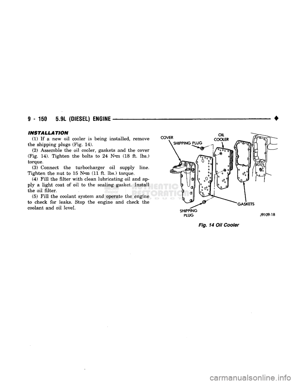
(1) If a new oil cooler is being installed, remove
the shipping plugs (Fig. 14). (2) Assemble the oil cooler, gaskets and the cover
(Fig. 14). Tighten the bolts to 24 N-m (18 ft. lbs.)
torque. (3) Connect the turbocharger oil supply line.
Tighten the nut to 15 N-m (11 ft. lbs.) torque. (4) Fill the filter with clean lubricating oil and ap
ply a light coat of oil to the sealing gasket. Install the oil filter. (5) Fill the coolant system and operate the engine
to check for leaks. Stop the engine and check the
coolant and oil level.
SHIPPING
PLUG
J9109-18
Fig.
14 Oil
Cooler
Page 763 of 1502
11
- 4
EXHAUST SYSTEM
AND
INTAKE MANIFOLD
•
SERVICE
PROCEDURES (GASOLINE ENGINES)
INDEX
page
Catalytic
Converters
4
Engine
Exhaust
Manifold
: . . . . 15
Exhaust
Heat
Shields
5
Exhaust
Pipe
4
page
Exhaust
Tailpipe
. 5
Intake Manifold
13
Mufflers
4
EXHAUST PIPE Refer
to
Figs.
1, 4, 5 and 6 for the
following proce
dure.
REMOVAL (1) Raise vehicle
on a
hoist.
(2) Apply penetrating
oil to
bolts
and
clamp nuts.
(3) Remove clamps, supports
and
bolts from
ex
haust pipe.
(4) Remove
the
exhaust pipe.
(5) Clean ends
of
pipes
to
assure mating
of all
parts.
(6) Discard rusted clamps, broken
or
worn supports
and attaching parts. Replace
a
component with orig
inal equipment parts,
or
equivalent. This will assure
proper alignment with other parts
in the
system
and
provide acceptable exhaust noise levels.
INSTALLATION (1) Assemble exhaust pipe, supports
and
clamps
loosely
to
permit proper alignment
of all
parts. (2) Position
the
exhaust pipe
for
proper clearance
with underbody parts.
(3)
On
models using ball-type connections, alter
nately tighten bolts
to
assure flanges
are
even
and
parallel.
(4) Tighten
all
clamp nuts, bolts
and
support
bracket nuts/bolts
to the
proper torques (Refer
to
Figs.
1, 4, 5 and 6).
(5) Lower
the
vehicle.
(6) Start
the
engine
and
check
for
leaks.
CATALYTIC CONVERTERS Refer
to
Figs.
1, 4, 5 and 6 for the
following proce
dure.
REMOVAL (1) Raise vehicle
on a
hoist.
(2) Apply penetrating
oil to
bolts
and
clamp nuts.
(3) Remove clamps, isolators
and
bolts.
(4) Remove
the
catalytic converter.
(5) Clean ends
of
pipes
and
muffler
to
assure mat
ing
of all
parts. (6) Discard rusted clamps, broken
or
worn isola
tors,
supports
and
attaching parts. Replace
a
compo
nent with original equipment parts,
or
equivalent. This will assure proper alignment with other parts
in
the system
and
provide acceptable exhaust noise lev
els.
INSTALLATION (1) Assemble converter, isolators
and
clamps
loosely
to
permit proper alignment
of all
parts. (2) Position
the
converter
for
proper clearance with
exhaust heat shields
and
underbody parts.
(3) Tighten
all
clamp nuts, bolts
and
support
bracket nuts/bolts
to the
proper torques (Refer
to
Figs.
1, 4, 5 and 6).
(4) Lower
the
vehicle.
(5) Start
the
engine
and
check
for
leaks.
MUFFLERS Refer
to
Figs.
1, 2, 4, 5, 6 and 7 for the
following
procedure.
REMOVAL (1) Raise vehicle
on a
hoist.
(2) Apply penetrating
oil to
bolts
and
clamp nuts. (3) Remove clamps, isolators
and
bolts.
(4) Remove
the
muffler.
(5) Clean ends
of
pipes
and
muffler
to
assure mat
ing
of all
parts.
(6) Discard rusted clamps, broken
or
worn isola
tors,
supports
and
attaching parts. Replace
a
compo
nent with original equipment parts,
or
equivalent.
This will assure proper alignment with other parts
in
the system
and
provide acceptable exhaust noise lev
els.
INSTALLATION (1) Assemble muffler, isolators
and
clamps loosely
to permit proper alignment
of all
parts. (2) Position
the
muffler
for
proper clearance with
the underbody parts.
(3) Tighten
all
clamp nuts, bolts
and
support
bracket nuts/bolts
to the
proper torques (Refer
to
Figs.
1, 2, 4, 5, 6 and 7).