air condition DODGE TRUCK 1993 Service Manual Online
[x] Cancel search | Manufacturer: DODGE, Model Year: 1993, Model line: TRUCK, Model: DODGE TRUCK 1993Pages: 1502, PDF Size: 80.97 MB
Page 618 of 1502
•
ENGINES
9 - 13
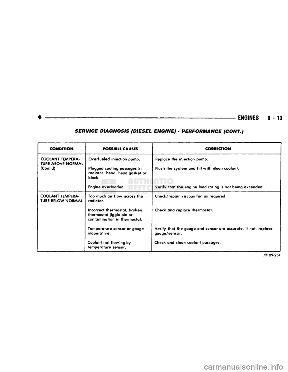
CONDITION
POSSIBLE
CAUSES
COfiiiECTION
COOLANT
TEMPERA
TURE
ABOVE
NORMAL
(Cont'd)
Overfueled injection pump.
Plugged
cooling
passages
in
radiator, head, head gasket or
block.
Engine
overloaded.
Replace
the injection
pump.
Flush
the
system
and
fill
with
clean coolant.
Verify
that
the engine load rating is not being exceeded.
COOLANT
TEMPERA
TURE
BELOW
NORMAL
Too
much air flow
across
the
radiator.
Incorrect thermostat, broken
thermostat jiggle pin or
contamination
in thermostat.
Temperature
sensor
or
gauge
inoperative.
Coolant
not flowing by
temperature
sensor.
Check/repair
viscous
fan as required.
Check
and replace thermostat.
Verify
that
the
gauge
and
sensor
are accurate. If not, replace
gauge/sensor.
Check
and clean coolant
passages.
J9109-254
SERVICE DIAGNOSIS (DIESEL ENGINE) • PERFORMANCE (CONT.)
Page 620 of 1502
•
• —
ENGINES
9 - 15
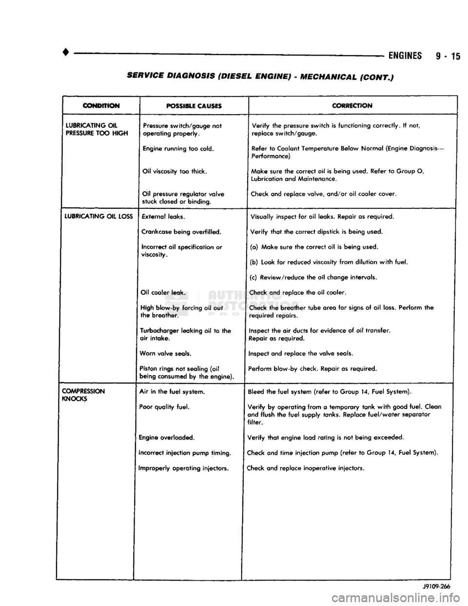
CONDITION
POSSIBLE CAUSES
CORRECTION
LUBRICATING
OIL
PRESSURE
TOO
HIGH
Pressure
switch/gauge
not
operating
properly.
Verify
the
pressure
switch
is
functioning
correctly.
If not,
replace
switch/gauge.
Engine
running
too
cold.
Refer
to
Coolant
Temperature
Below
Normal
(Engine
Diagnosis-
Performance)
Oil
viscosity
too thick. Make
sure
the
correct
oil Is
being
used.
Refer
to
Group
O,
Lubrication
and
Maintenance.
Oil
pressure
regulator
valve
stuck
closed
or
binding.
Check
and replace valve, and/or oil cooler cover.
LUBRICATING
OIL
LOSS
External
leaks.
Visually
inspect for oil
leaks.
Repair as required.
Crankcase
being
overfilled. Verify that the correct dipstick is being
used.
incorrect
oil specification or
viscosity.
(a) Make sure the correct oil is being
used.
(b)
Look
for reduced
viscosity
from dilution with fuel.
(c) Review/reduce the oil
change
intervals.
Oil
cooler
leak.
Check
and replace the oil cooler.
High
blow-by
forcing oil out
the breather.
Check
the breather tube area for
signs
of oil
loss.
Perform the
required repairs.
Turbocharger
leaking
oil to the
air intake.
Inspect
the air
ducts
for evidence of oil transfer.
Repair
as required.
Worn
valve
seals.
Inspect
and replace the valve
seals.
Piston
rings
not
sealing
(oil
being
consumed
by the
engine).
Perform
blow-by check. Repair as required.
COMPRESSION
KNOCKS
Air in the
fuel
system.
Poor
quality
fuel.
Bleed
the fuel
system
(refer
to
Group
14, Fuel
System).
Verify by operating from a temporary tank with
good
fuel. Clean
and
flush the fuel
supply
tanks.
Replace fuel/water separator
filter.
Engine
overloaded. Verify that engine load rating is not being exceeded.
Incorrect injection
pump
timing.
Check
and time injection pump
(refer
to
Group
14, Fuel
System).
Improperly
operating
injectors.
Check
and replace inoperative injectors. J9109-266 SERVICE DIAGNOSIS (DIESEL ENGINE) - MECHANICAL (CONT.)
Page 621 of 1502
9 - 16
ENGINES
•
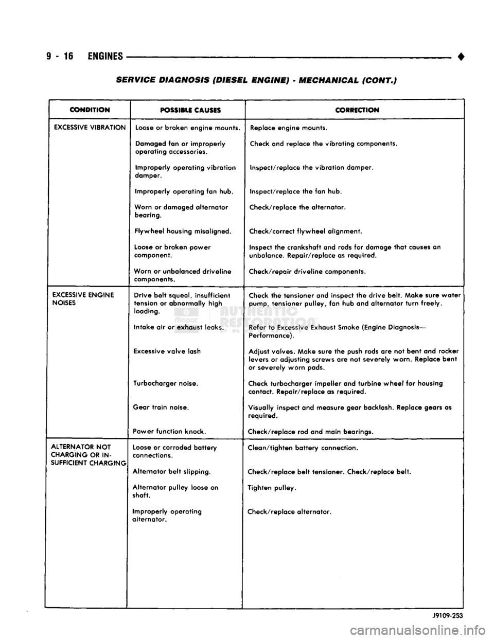
CONDITION
POSSIBLE
CAUSES
CORRECTION
EXCESSIVE
VIBRATION
Loose
or broken engine mounts.
Replace
engine mounts.
Damaged
fan or improperly
operating
accessories.
Check
and replace the vibrating components.
Improperly operating vibration
clamper. Inspect/replace the vibration damper.
Improperly operating fan hub. Inspect/replace the fan hub.
Worn
or
damaged
alternator
bearing.
Check/replace
the alternator.
Flywheel
housing
misaligned. Check/correct flywheel alignment.
Loose
or broken power
component.
Inspect
the crankshaft and rods for damage
that
causes
an
unbalance.
Repair/replace as required.
Worn
or unbalanced driveline
components.
Check/repair driveline components.
EXCESSIVE
ENGINE
NOISES
Drive belt squeal, insufficient
tension
or abnormally high
loading.
Check
the tensioner and inspect the drive belt. Make sure water
pump,
tensioner pulley, fan hub and alternator turn
freely.
Intake air or exhaust leaks. Refer to
Excessive
Exhaust
Smoke
(Engine
Diagnosis—
Performance).
Excessive
valve
lash
Adjust
valves.
Make sure the
push
rods are not bent and rocker
levers or adjusting screws are not severely worn. Replace bent
or
severely worn
pads.
Turbocharger
noise.
Check
turbocharger impeller and turbine wheel for housing
contact. Repair/replace as required.
Gear
train
noise.
Visually
inspect and measure gear
backlash.
Replace gears as
required.
Power
function knock.
Check/replace
rod and main bearings.
ALTERNATOR
NOT
CHARGING
OR IN-
SUFFICIENT
CHARGING
Loose
or corroded battery
connections.
Alternator belt slipping. Clean/tighten battery connection.
Check/replace
belt tensioner. Check/replace belt.
Alternator pulley loose on
shaft.
Tighten pulley.
Improperly operating
alternator.
Check/replace
alternator.
J9109-253
SERVICE DIAGNOSIS (DIESEL ENGINE) - MECHANICAL (CONT.)
Page 625 of 1502
TRANSFER
CASE
INSULATOR
MOUNTING PLATE
NUT(B
RAIL
ASSEMBLY
SPACER
UPPER
INSULATOR
NUT®
LOWER
INSULATOR
J9109-242
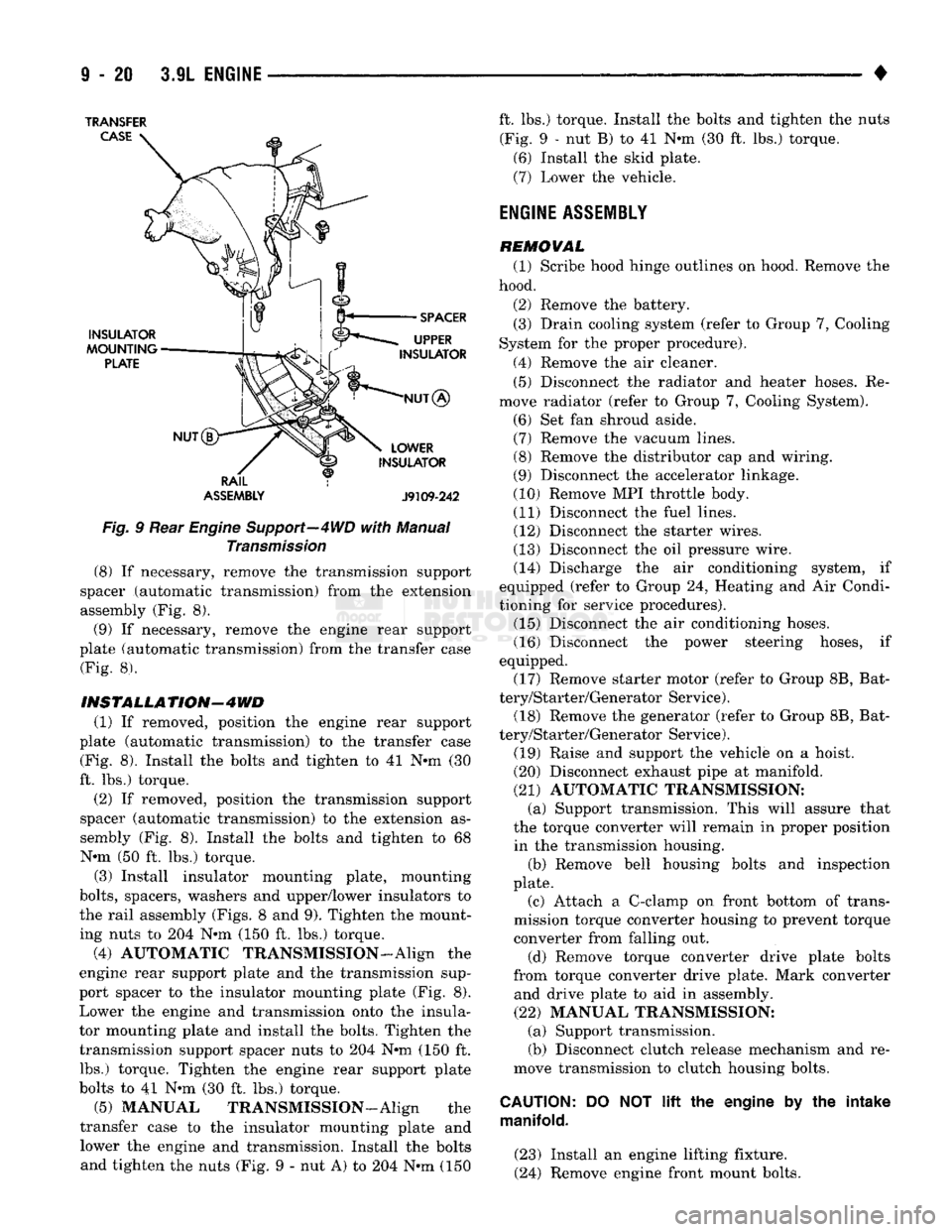
Fig.
9 Rear
Engine
Support—4WD
with
Manual
Transmission
(8) If necessary, remove the transmission support
spacer (automatic transmission) from the extension
assembly (Fig. 8).
(9) If necessary, remove the engine rear support
plate (automatic transmission) from the transfer case (Fig. 8).
INSTALLATION-4WD
(1) If removed, position the engine rear support
plate (automatic transmission) to the transfer case (Fig. 8). Install the bolts and tighten to 41 N-m (30
ft. lbs.) torque.
(2) If removed, position the transmission support
spacer (automatic transmission) to the extension as
sembly (Fig. 8). Install the bolts and tighten to 68 N-m (50 ft. lbs.) torque.
(3) Install insulator mounting plate, mounting
bolts,
spacers, washers and upper/lower insulators to
the rail assembly (Figs. 8 and 9). Tighten the mount
ing nuts to 204 N*m (150 ft. lbs.) torque.
(4) AUTOMATIC TRANSMISSION-Align the
engine rear support plate and the transmission sup
port spacer to the insulator mounting plate (Fig. 8). Lower the engine and transmission onto the insula
tor mounting plate and install the bolts. Tighten the transmission support spacer nuts to 204 N-m (150 ft. lbs.) torque. Tighten the engine rear support plate
bolts to 41 N-m (30 ft. lbs.) torque.
(5) MANUAL TRANSMISSION—Align the
transfer case to the insulator mounting plate and lower the engine and transmission. Install the bolts and tighten the nuts (Fig. 9 - nut A) to 204 N-m (150 ft. lbs.) torque. Install the bolts and tighten the nuts
(Fig. 9 - nut B) to 41 N-m (30 ft. lbs.) torque. (6) Install the skid plate.
(7) Lower the vehicle.
ENGINE
ASSEMBLY
REMOVAL (1) Scribe hood hinge outlines on hood. Remove the
hood.
(2) Remove the battery. (3) Drain cooling system (refer to Group 7, Cooling
System for the proper procedure).
(4) Remove the air cleaner. (5) Disconnect the radiator and heater hoses. Re
move radiator (refer to Group 7, Cooling System).
(6) Set fan shroud aside. (7) Remove the vacuum lines. (8) Remove the distributor cap and wiring.
(9) Disconnect the accelerator linkage.
(10) Remove MPI throttle body. (11) Disconnect the fuel lines. (12) Disconnect the starter wires.
(13) Disconnect the oil pressure wire. (14) Discharge the air conditioning system, if
equipped (refer to Group 24, Heating and Air Condi
tioning for service procedures). (15) Disconnect the air conditioning hoses.
(16) Disconnect the power steering hoses, if
equipped. (17) Remove starter motor (refer to Group 8B, Bat
tery/Starter/Generator Service). (18) Remove the generator (refer to Group 8B, Bat
tery/Starter/Generator Service).
(19) Raise and support the vehicle on a hoist.
(20) Disconnect exhaust pipe at manifold.
(21) AUTOMATIC TRANSMISSION: (a) Support transmission. This will assure that
the torque converter will remain in proper position in the transmission housing. (b) Remove bell housing bolts and inspection
plate.
(c) Attach a C-clamp on front bottom of trans
mission torque converter housing to prevent torque
converter from falling out.
(d) Remove torque converter drive plate bolts
from torque converter drive plate. Mark converter and drive plate to aid in assembly.
(22) MANUAL TRANSMISSION: (a) Support transmission.
(b) Disconnect clutch release mechanism and re
move transmission to clutch housing bolts.
CAUTION:
DO NOT
lift
the engine by the intake
manifold.
(23) Install an engine lifting fixture.
(24) Remove engine front mount bolts.
Page 626 of 1502
•
3.9L
ENGINE
9 - 21 (25) Lower the vehicle.
(26) On automatic transmission vehicles, discon
nect the engine from the torque converter drive
plate. On manual transmission vehicles, move engine forward until drive pinion shaft clears the clutch
disc.
Remove engine from engine compartment. (27) Install engine assembly on engine repair
stand.
INSTALLATION (1) Remove engine from the repair stand and posi
tion in the engine compartment.
(2) Install engine support fixture.
(3) Raise and support the vehicle on a hoist.
(4)
AUTOMATIC TRANSMISSION: (a) Position the torque converter and drive plate.
Install torque converter drive plate bolts. Tighten
the bolts to 31 Nnn (270 in. lbs.) torque.
(b) Install the engine front mounts.
(c) Install bell housing bolts. Tighten the bolts to
41 N-m (30 ft. lbs.) torque.
(d) Remove C-clamp.
(e) Install the inspection plate.
(5) MANUAL TRANSMISSION: (a) Position the drive pinion shaft to the clutch
disc.
(b) Connect the clutch release mechanism and
install the transmission to clutch bolts. Tighten the
bolts to 68 N-m (50 ft. lbs.) torque.
(c) Install the engine front mounts.
(6) Remove transmission support.
(7) Install exhaust pipe to manifold.
(8) Lower the vehicle.
(9) Remove engine lifting fixture.
(10) Install the generator (refer to Group 8B, Bat
tery/Starter/Generator Service). (11) Install starter motor (refer to Group 8B, Bat
tery/Starter/Generator Service). (12) Connect power steering hoses, if equipped.
(13) Connect air conditioning hoses.
(14) Evacuate and charge the air conditioning sys
tem, if equipped (refer to Group 24, Heater and Air Conditioning for service procedures). (15) Using a new gasket, install MPI throttle body.
Tighten the throttle body bolts to 23 N-m (200 in. lbs.) torque. (16) Connect the accelerator linkage.
(17) Connect the starter wires. (18) Connect the oil pressure wire.
(19) Install the distributor cap and wiring.
(20) Connect the vacuum lines.
(21) Connect the fuel lines.
(22) Install the radiator (refer to Group 7, Cooling
System). Connect the radiator hoses and heater
hoses.
(23) Install fan shroud in position. (24) Fill cooling system (refer to Group 7, Cooling
System for the proper procedures). (25) Install the air cleaner.
(26) Install the battery.
(27) Warm engine and adjust.
(28) Install hood and line up with the scribe
marks. (29) Road test vehicle.
CYLINDER
HEAD COVER
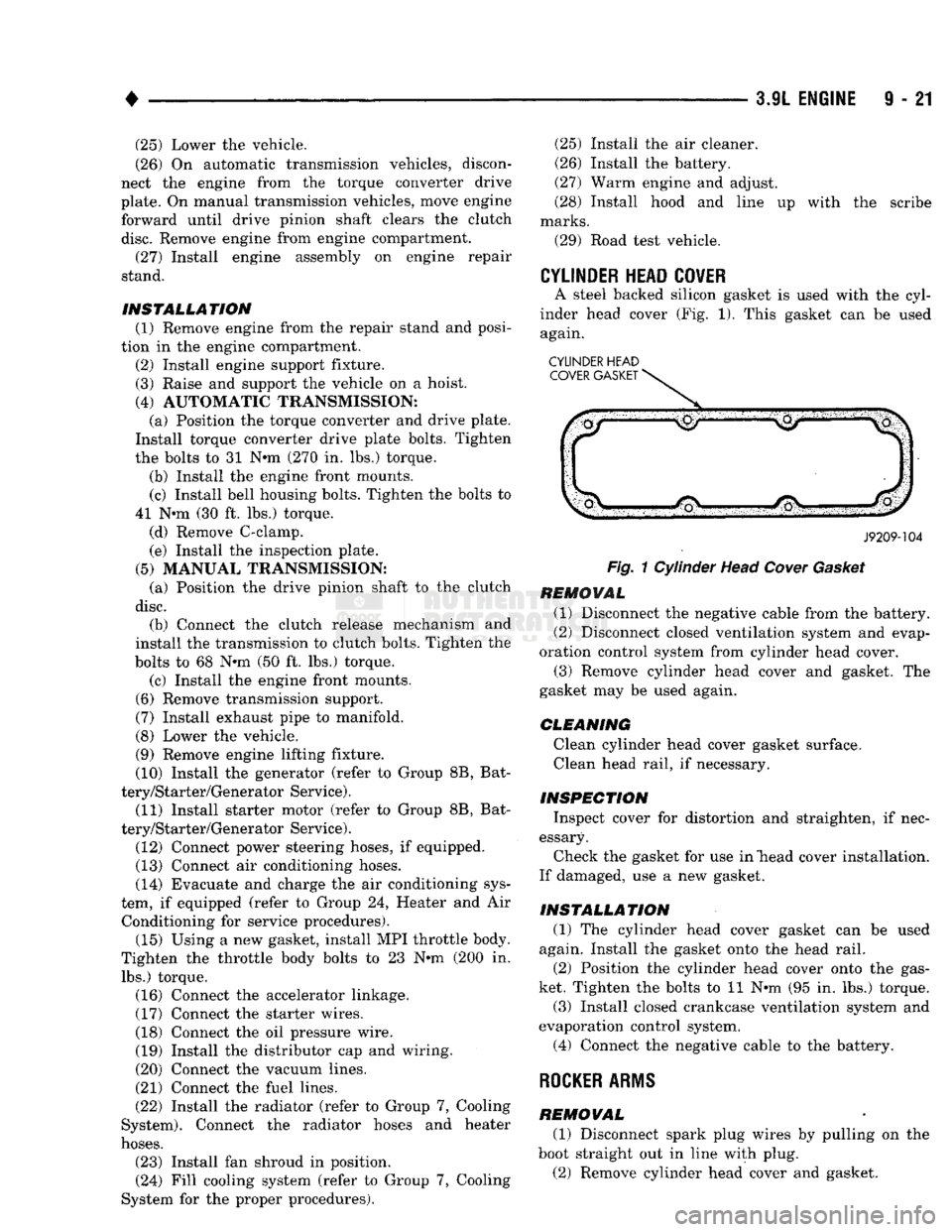
A steel backed silicon gasket is used with the cyl
inder head cover (Fig. 1). This gasket can be used again.
CYLINDER HEAD COVER GASKET
J9209-104
Fig.
1 Cylinder Head
Cover
Gasket
REMOVAL (1) Disconnect the negative cable from the battery.
(2) Disconnect closed ventilation system and evap
oration control system from cylinder head cover. (3) Remove cylinder head cover and gasket. The
gasket may be used again.
CLEANING Clean cylinder head cover gasket surface. Clean head rail, if necessary.
INSPECTION Inspect cover for distortion and straighten, if nec
essary. Check the gasket for use in "head cover installation.
If damaged, use a new gasket.
INSTALLATION (1) The cylinder head cover gasket can be used
again. Install the gasket onto the head rail.
(2) Position the cylinder head cover onto the gas
ket. Tighten the bolts to 11 N-m (95 in. lbs.) torque. (3) Install closed crankcase ventilation system and
evaporation control system.
(4) Connect the negative cable to the battery.
ROCKER
ARMS
REMOVAL (1) Disconnect spark plug wires by pulling on the
boot straight out in line with plug.
(2) Remove cylinder head cover and gasket.
Page 632 of 1502
•
3.9L
ENGINE
9 - 27 (2) If valves or seats are reground, check valve
stem height. If valve is too long, replace cylinder
head.
(3) Install new seals on all valve guides. Install
valve springs and valve retainers.
(4) Compress valve springs with Valve Spring
Compressor Tool MD-998772A, install locks and re
lease tool. If valves and/or seats are ground, measure
the installed height of springs. Make sure the mea surement is taken from bottom of spring seat in cyl
inder head to the bottom surface of spring retainer. If
spacers are installed, measure from the top of spacer.
If height is greater than 42.86 mm (1-11/16 inches), install a 1.587 mm (1/16 inch) spacer in head coun-
terbore. This should bring spring height back to nor
mal 41.27 to 42.86 mm (1-5/8 to
1-11/16
inch).
VALVE STEM SEAL
/
SPRING REPLACEMENT
This procedure is done with the cylinder head in
stalled. (1) Set engine basic timing to TDC and remove air
cleaner. (2) Remove cylinder head covers and spark plugs.
(3) Remove coil wire from distributor and secure to
good ground to prevent engine from starting. (4) Using suitable socket and flex handle at crank
shaft retaining bolt, turn engine so the No.l piston is
at Top Dead Center on the compression stroke. (5) Remove rocker arms.
(6) With air hose attached to an adapter installed
in No.l spark plug hole, apply 620-689 kPa (90-100
psi) air pressure. (7) Using Valve Spring Compressor Tool
MD-998772A, compress valve spring and remove re
tainer valve locks and valve spring. (8) Install seals on the exhaust valve stem and po
sition down against valve guides. (9) The intake valve stem seals should be pushed
firmly and squarely over the valve guide using the valve stem as a guide. DO NOT force seal against
top of guide. When installing the valve retainer
locks,
compress the spring only enough to install the
locks.
(10) Follow the same procedure on the remaining 5
cylinders using the firing sequence
1-6-5-4-3-2.
Make sure piston in cylinder is at TDC on the valve spring
that is being removed. (11) Remove adapter from the No.l spark plug
hole.
(12) Install rocker arms.
(13) Install covers and coil wire to distributor.
(14) Install air cleaner.
(15) Road test vehicle.
HYDRAULIC
TAPPETS
Before disassembling any part of the engine to cor
rect tappet noise, check the oil pressure. If vehicle
has no oil pressure gauge, install a reliable gauge at the pressure sending unit. The pressure should be be
tween 207-552 kPa (30-80 psi) at 3,000 RPM.
Check the oil level after the engine reaches normal
operating temperature. Allow 5 minutes to stabilize
oil level, check dipstick.
The oil level in the pan should never be above the
FULL mark or below the ADD OIL mark on dipstick.
Either of these 2 conditions could be responsible for
noisy tappets.
OIL
LEWEL
HIGH
If oil level is above the FULL mark, it is possible
for the connecting rods to dip into the oil. With the engine running, this condition could create foam in
the oil pan. Foam in oil pan would be fed to the hy draulic tappets by the oil pump causing them to lose
length and allow valves to seat noisily.
LOW
Low oil level may allow oil pump to take in air.
When air is fed to the tappets, they lose length
which allows valves to seat noisily. Any leaks on in
take side of oil pump through which air can be drawn will create the same tappet action. Check the
lubrication system from the intake strainer to the
pump cover, including the relief valve retainer cap.
When tappet noise is due to aeration, it may be in
termittent or constant, and usually more than 1 tap
pet will be noisy. When oil level and leaks have been corrected, operate the engine at fast idle. Run engine
for a sufficient time to allow all of the air inside the
tappets to be bled out.
TAPPET
NOISE DIAGNOSIS
(1) To determine source of tappet noise, operate en
gine at idle with cylinder head covers removed. (2) Feel each valve spring or rocker arm to detect
noisy tappet. The noisy tappet will cause the affected
spring and/or rocker arm to vibrate or feel rough in
operation.
Worn valve guides or cocked springs are some
times mistaken for noisy tappets. If such is the
case, noise may be dampened by applying side
thrust on the valve spring. If noise is not appre ciably reduced, it can be assumed the noise is in
the tappet. Inspect the rocker arm push rod sockets and push rod ends for wear.
(3) Valve tappet noise ranges from light noise to a
heavy click. A light noise is usually caused by exces sive leak down around the unit plunger or by the
plunger partially sticking in the tappet body cylin der. The tappet should be replaced. A heavy click is
caused by a tappet check valve not seating or by for
eign particles becoming wedged between the plunger
and the tappet body. This will cause the plunger to
stick in the down position. This heavy click will be
Page 639 of 1502
OIL PAN
REMOVAL
(1) Disconnect the negative cable from the battery.
(2) Remove engine oil dipstick.
(3) Raise vehicle.
(4) Drain engine oil.
(5)
Remove exhaust pipe.
(6) Remove left engine to transmission strut.
(7) Remove oil pan and one-piece gasket.
CLEANING Clean the block and pan gasket surfaces.
Trim or remove excess sealant film in the rear
main cap oil pan gasket groove. DO NOT remove
the sealant inside the rear main cap slots.
If present, trim excess sealant from inside the en
gine.
Clean oil pan in solvent and wipe dry with a clean
cloth.
Clean oil screen and pipe thoroughly in clean sol
vent. Inspect condition of screen.
INSPECTION Inspect oil drain plug and plug hole for stripped or
damaged threads. Repair as necessary. Inspect oil pan mounting flange for bends or distor
tion. Straighten flange, if necessary.
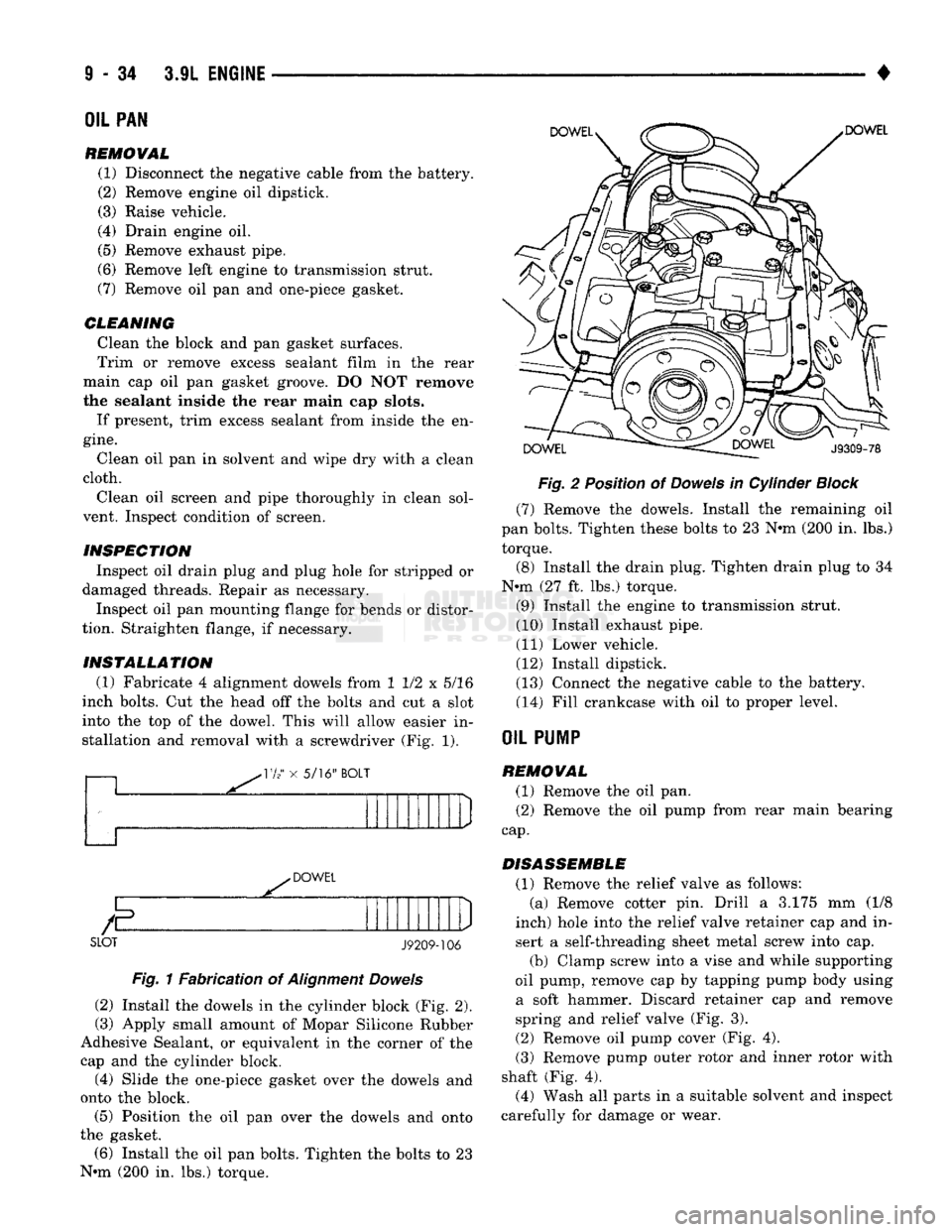
INSTALLATION (1) Fabricate 4 alignment dowels from 1 1/2 x 5/16
inch bolts. Cut the head off the bolts and cut a slot
into the top of the dowel. This will allow easier in stallation and removal with a screwdriver (Fig. 1).
11/2"
x 5/16" BOLT
,
DOWEL
SLOT
J9209-106
Fig. 1 Fabrication of Alignment Dowels
(2) Install the dowels in the cylinder block (Fig. 2).
(3) Apply small amount of Mopar Silicone Rubber
Adhesive Sealant, or equivalent in the corner of the cap and the cylinder block.
(4) Slide the one-piece gasket over the dowels and
onto the block. (5) Position the oil pan over the dowels and onto
the gasket. (6) Install the oil pan bolts. Tighten the bolts to 23
N-m (200 in. lbs.) torque. Fig. 2 Position of Dowels in Cylinder
Block
(7) Remove the dowels. Install the remaining oil
pan bolts. Tighten these bolts to 23 N-m (200 in. lbs.) torque.
(8) Install the drain plug. Tighten drain plug to 34
N-m (27 ft. lbs.) torque.
(9) Install the engine to transmission strut.
(10) Install exhaust pipe.
(11) Lower vehicle.
(12) Install dipstick.
(13) Connect the negative cable to the battery. (14) Fill crankcase with oil to proper level.
OIL
PU1P
REMOVAL (1) Remove the oil pan. (2) Remove the oil pump from rear main bearing
cap.
DISASSEMBLE (1) Remove the relief valve as follows: (a) Remove cotter pin. Drill a 3.175 mm (1/8
inch) hole into the relief valve retainer cap and in
sert a self-threading sheet metal screw into cap. (b) Clamp screw into a vise and while supporting
oil pump, remove cap by tapping pump body using a soft hammer. Discard retainer cap and remove
spring and relief valve (Fig. 3).
(2) Remove oil pump cover (Fig. 4).
(3) Remove pump outer rotor and inner rotor with
shaft (Fig. 4). (4) Wash all parts in a suitable solvent and inspect
carefully for damage or wear.
Page 655 of 1502
TRANSFER
CASE
TRANSFER
CASE
ENGINE
REAR
SUPPORT PLATE
EXTENSION
ASSEMBLY
TRANSMISSION
SUPPORT
SPACER
SPACER
UPPER
INSULATOR
INSULATOR
MOUNTING
PLATE
LOWER
INSULATOR
fT^RAIL
J9109-244
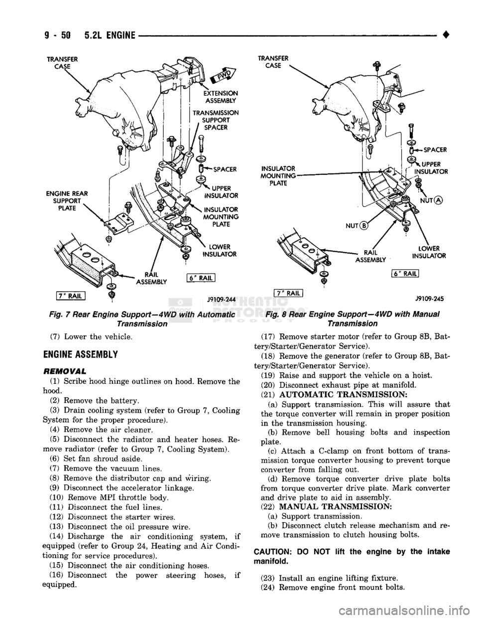
Fig,
7 Rear Engine Support—4WD
with
Automatic
Transmission
(7)
Lower the vehicle.
ENGINE
ASSEMBLY
REMOVAL
(1) Scribe hood hinge outlines on hood. Remove the
hood. (2) Remove the battery.
(3) Drain cooling system (refer to Group 7, Cooling
System for the proper procedure). (4) Remove the air cleaner.
(5) Disconnect the radiator and heater hoses. Re
move radiator (refer to Group 7, Cooling System). (6) Set fan shroud aside.
(7)
Remove the vacuum lines.
(8) Remove the distributor cap and wiring.
(9) Disconnect the accelerator linkage.
(10) Remove MPI throttle body.
(11) Disconnect the fuel lines.
(12) Disconnect the starter wires.
(13) Disconnect the oil pressure wire.
(14) Discharge the air conditioning system, if
equipped (refer to Group 24, Heating and Air Condi
tioning for service procedures).
(15) Disconnect the air conditioning hoses.
(16) Disconnect the power steering hoses, if
equipped.
INSULATOR
MOUNTING
PLATE
SPACER
UPPER
L\ f
INSULATOR
NUT®
RAIL
ASSEMBLY
LOWER
INSULATOR
l6ff
RAIL
I
J9109-245
Fig.
8 Rear
Engine
Support—4WD
with
Manual
Transmission
(17) Remove starter motor (refer to Group 8B, Bat
tery/Starter/Generator Service).
(18) Remove the generator (refer to Group 8B, Bat
tery/Starter/Generator Service).
(19) Raise and support the vehicle on a hoist.
(20) Disconnect exhaust pipe at manifold.
(21)
AUTOMATIC TRANSMISSION: (a) Support transmission. This will assure that
the torque converter will remain in proper position in the transmission housing. (b) Remove bell housing bolts and inspection
plate. (c) Attach a C-clamp on front bottom of trans
mission torque converter housing to prevent torque
converter from falling out. (d) Remove torque converter drive plate bolts
from torque converter drive plate. Mark converter and drive plate to aid in assembly.
(22)
MANUAL TRANSMISSION; (a) Support transmission.
(b) Disconnect clutch release mechanism and re
move transmission to clutch housing bolts.
CAUTION:
manifold.
DO
NOT lift the
engine
by the
intake
(23) Install an engine lifting fixture.
(24) Remove engine front mount bolts.
Page 656 of 1502
•
5.2L
ENGINE
9 - 51 (25) Lower the vehicle.
(26) On automatic transmission vehicles, discon
nect the engine from the torque converter drive
plate. On manual transmission vehicles, move engine forward until drive pinion shaft clears the clutch
disc.
Remove engine from engine compartment.
(27) Install engine assembly on engine repair
stand.
INSTALLATION
(1) Remove engine from the repair stand and posi
tion in the engine compartment.
(2) Install an engine support fixture.
(3) Raise and support the vehicle on a hoist.
(4) AUTOMATIC TRANSMISSION: (a) Position the torque converter and drive plate.
Install torque converter drive plate bolts. Tighten
the bolts to 31 N-m (270 in. lbs.) torque.
(b) Install the engine front mounts.
(c) Install bell housing bolts. Tighten the bolts to
41 N-m (30 ft. lbs.) torque.
(d) Remove C-clamp.
(e) Install the inspection plate.
(5) MANUAL TRANSMISSION: (a) Position the drive pinion shaft to the clutch
disc.
(b) Connect the clutch release mechanism and
install the transmission to clutch bolts. Tighten the
bolts to 68 N-m (50 ft. lbs.) torque.
(c) Install the engine front mounts.
(6) Remove transmission support.
(7) Install exhaust pipe to manifold. (8) Lower the vehicle.
(9) Remove engine lifting fixture. (10) Install the generator (refer to Group 8B, Bat
tery/Starter/ Generator Service). (11) Install the starter motor (refer to Group 8B,
Battery/Starter/Generator Service). (12) Connect power steering hoses, if so equipped.
(13) Connect air conditioning hoses.
(14) Evacuate and charge the air conditioning sys
tem, if equipped (refer to Group 24, Heater and Air Conditioning for service procedures).
(15) Using a new gasket, install MPI throttle body.
Tighten the throttle body bolts to 23 N-m (200 in. lbs.) torque. (16) Connect the accelerator linkage.
(17) Connect the starter wires.
(18) Connect the oil pressure wire. (19) Install the distributor cap and wiring.
(20) Connect the vacuum lines.
(21) Connect the fuel lines,
(22) Install the radiator (refer to Group 7, Cooling
System). Connect the radiator hoses and heater
hoses.
(23) Install fan shroud in position.
(24) Fill cooling system (refer to Group 7, Cooling
System for the proper procedure). (25) Install the air cleaner.
(26) Install the battery. (27) Warm engine and adjust.
(28) Install hood and line up with the scribe
marks. (29) Road test vehicle.
CYLIiiER
HEAD
COVER
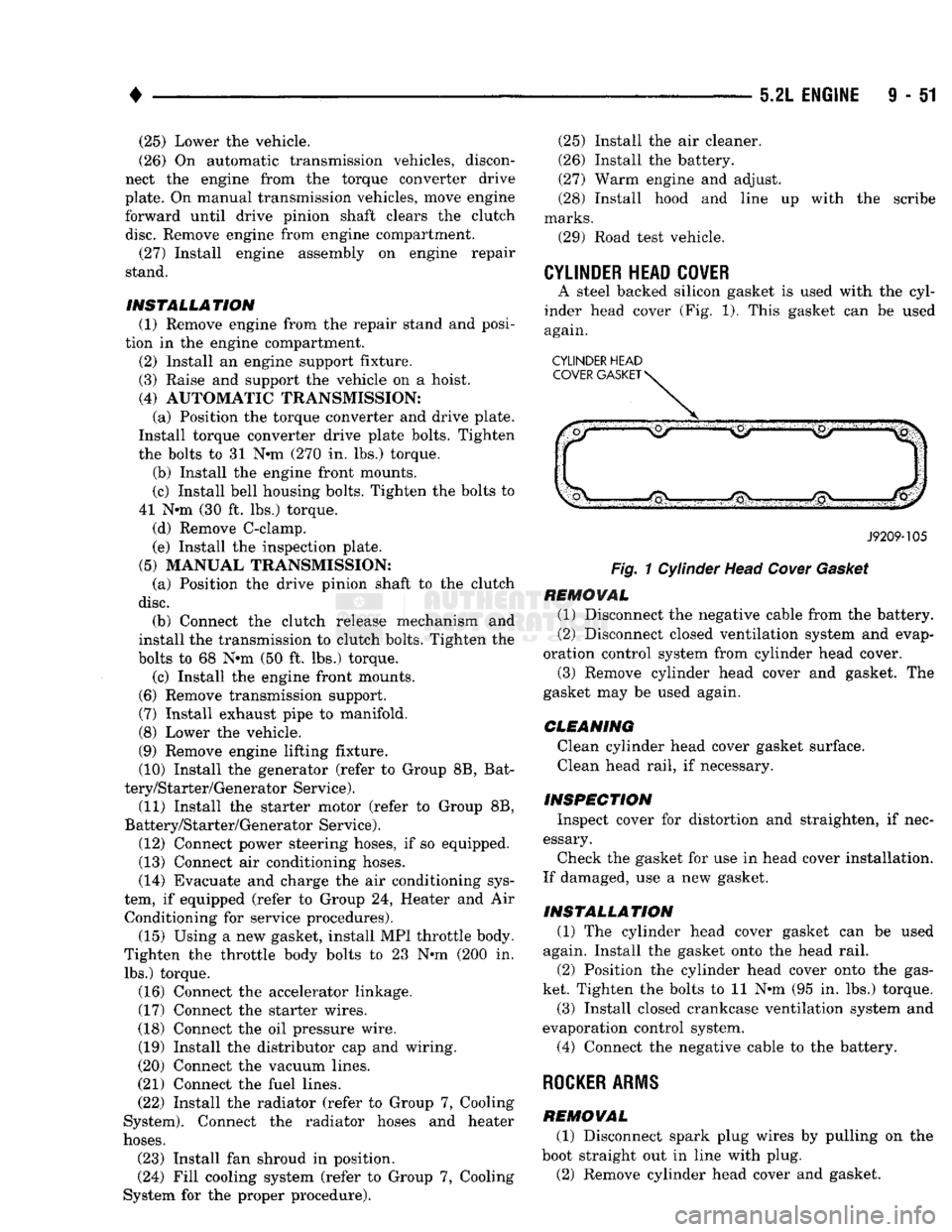
A steel backed silicon gasket is used with the cyl
inder head cover (Fig. 1). This gasket can be used
again.
CYLINDER HEAD
J9209-105
Fig.
1 Cylinder Head
Cover
Gasket
REMOVAL
(1) Disconnect the negative cable from the battery.
(2) Disconnect closed ventilation system and evap
oration control system from cylinder head cover.
(3) Remove cylinder head cover and gasket. The
gasket may be used again.
CLEANING
Clean cylinder head cover gasket surface. Clean head rail, if necessary.
INSPECTION
Inspect cover for distortion and straighten, if nec
essary.
Check the gasket for use in head cover installation.
If damaged, use a new gasket.
INSTALLATION
(1) The cylinder head cover gasket can be used
again. Install the gasket onto the head rail.
(2) Position the cylinder head cover onto the gas
ket. Tighten the bolts to 11 N-m (95 in. lbs.) torque.
(3) Install closed crankcase ventilation system and
evaporation control system.
(4) Connect the negative cable to the battery.
ROCKER ARMS
REMOVAL
(1) Disconnect spark plug wires by pulling on the
boot straight out in line with plug. (2) Remove cylinder head cover and gasket.
Page 661 of 1502
9
- 56 5.2L
ENGINE
•
VALVE
SPRING
RETAINER LOCK GROOVE
EXHAUST
VALVE
J9209-127 the spring load at test length. Fractional measure
ments are indicated on the table for finer adjust
ments. Refer to specifications to obtain specified
height and allowable tensions. Discard the springs
that do not meet specifications.
SPECIAL
TOOL
C-647
Fig.
14 Intake and
Exhaust
Valves
Fig.
15 Refacing
Valve
Seats
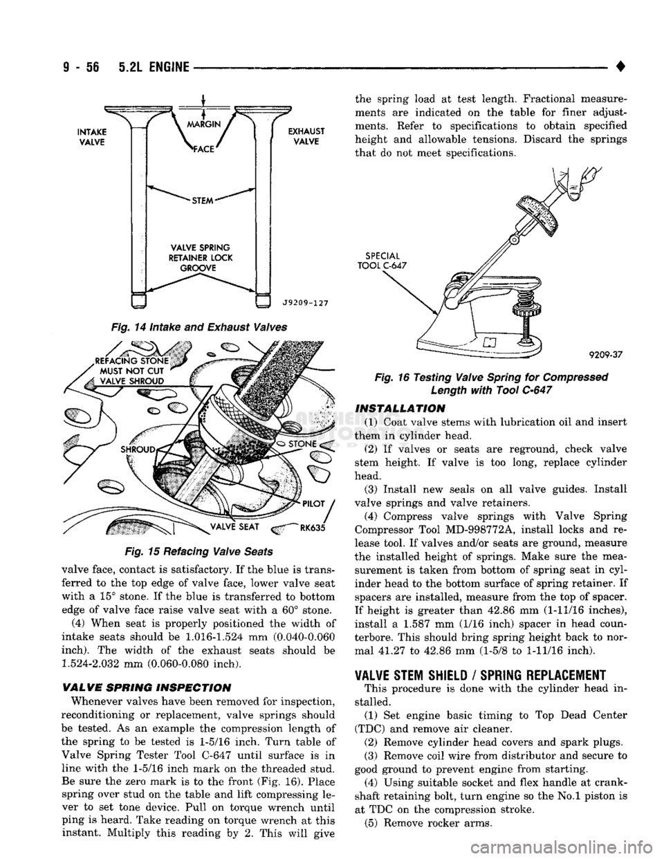
valve face, contact is satisfactory. If the blue is trans
ferred to the top edge of valve face, lower valve seat
with a 15° stone. If the blue is transferred to bottom edge of valve face raise valve seat with a 60° stone.
(4) When seat is properly positioned the width of
intake seats should be
1.016-1.524
mm (0.040-0.060
inch).
The width of the exhaust seats should be
1.524-2.032
mm (0.060-0.080 inch).
WALVE SPRING INSPECTION Whenever valves have been removed for inspection,
reconditioning or replacement, valve springs should
be tested. As an example the compression length of
the spring to be tested is
1-5/16
inch. Turn table of Valve Spring Tester Tool C-647 until surface is in line with the
1-5/16
inch mark on the threaded stud.
Be sure the zero mark is to the front (Fig. 16). Place spring over stud on the table and lift compressing le
ver to set tone device. Pull on torque wrench until ping is heard. Take reading on torque wrench at this instant. Multiply this reading by 2. This will give ^
9209-37
Fig.
16 Testing
Valve
Spring
for
Compressed
Length
with
Tool
C-647
INSTALLATION
(1) Coat valve stems with lubrication oil and insert
them in cylinder head.
(2) If valves or seats are reground, check valve
stem height. If valve is too long, replace cylinder
head.
(3) Install new seals on all valve guides. Install
valve springs and valve retainers.
(4) Compress valve springs with Valve Spring
Compressor Tool MD-998772A, install locks and re
lease tool. If valves and/or seats are ground, measure
the installed height of springs. Make sure the mea surement is taken from bottom of spring seat in cyl
inder head to the bottom surface of spring retainer. If spacers are installed, measure from the top of spacer.
If height is greater than 42.86 mm (1-11/16 inches),
install a 1.587 mm (1/16 inch) spacer in head coun-
terbore. This should bring spring height back to nor mal 41.27 to 42.86 mm (1-5/8 to
1-11/16
inch).
VALVE STEM SHIELD
/
SPRING REPLACEMENT
# This procedure is done with the cylinder head in
stalled. (1) Set engine basic timing to Top Dead Center
(TDC) and remove air cleaner. (2) Remove cylinder head covers and spark plugs.
(3) Remove coil wire from distributor and secure to
good ground to prevent engine from starting. (4) Using suitable socket and flex handle at crank
shaft retaining bolt, turn engine so the No.l piston is
at TDC on the compression stroke. (5) Remove rocker arms.