wheel size DODGE TRUCK 1993 Service Repair Manual
[x] Cancel search | Manufacturer: DODGE, Model Year: 1993, Model line: TRUCK, Model: DODGE TRUCK 1993Pages: 1502, PDF Size: 80.97 MB
Page 6 of 1502
INTRODUCTION
INTRODUCTION
DESIGNATIONS,
LABELS/PLATES/DECALS,
CODES
AND DIMENSIONS/WEIGHTS .
CONTENTS
page
MEASUREMENT
AND TORQUE
... 1 SPECIFICATIONS
page
. 11
DESIGNATIONS, LABELS/PLATES/DECALS, CODES
AND
DIMENSIONS/WEIGHTS
INDEX
page
Engine
and
Transmission/Transfer
Case
Identification
2
Engine/Transmission/GVWR
4
Equipment
Identification
Plate
3
International
Vehicle Control
and
Display
Symbols
10
Major Component
Identification 3
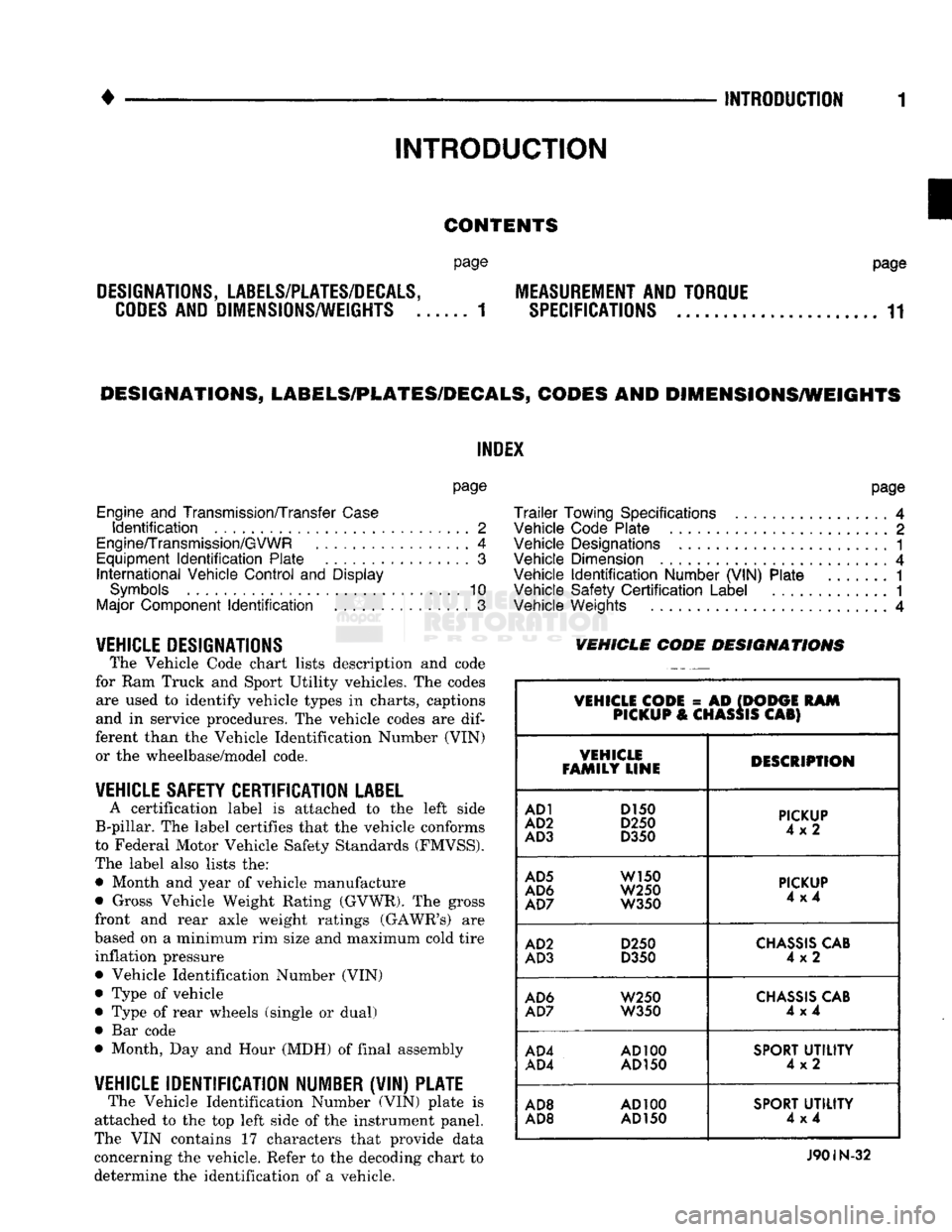
VEHICLE DESIGNATIONS The Vehicle Code chart lists description and code
for Ram Truck and Sport Utility vehicles. The codes are used to identify vehicle types in charts, captions
and in service procedures. The vehicle codes are
dif
ferent than the Vehicle Identification Number (VIN) or the wheelbase/model code.
VEHICLE SAFETY CERTIFICATION
LABEL
A certification label is attached to the left side
B-pillar. The label certifies that the vehicle conforms
to Federal Motor Vehicle Safety Standards (FMVSS).
The label also lists the: • Month and year of vehicle manufacture
• Gross Vehicle Weight Rating (GVWR). The gross
front and rear axle weight ratings (GAWR's) are
based on a minimum rim size and maximum cold tire inflation pressure Vehicle Identification Number (VIN)
Type of vehicle
Type of rear wheels (single or dual) Bar code
Month, Day and Hour (MDH) of final assembly
VEHICLE IDENTIFICATION NUMBER (VIN) PLATE The Vehicle Identification Number (VIN) plate is
attached to the top left side of the instrument panel.
The VIN contains 17 characters that provide data
concerning the vehicle. Refer to the decoding chart to
determine the identification of a vehicle.
page
Trailer
Towing Specifications
4
Vehicle Code Plate
2
Vehicle Designations
1
Vehicle Dimension
4
Vehicle
Identification
Number (VIN) Plate
1
Vehicle Safety
Certification
Label
............. 1
Vehicle Weights
4
VEHICLE CODE
DESIGNATIONS
VEHICLE CODE
= AD
(DODGE
RAM
PICKUP
&
CHASSIS
CAB)
VEHICLE
FAMILY LINE DESCRIPTION
AD1
D150
AD2
D250
AD3
D350
PICKUP
4x2
AD5
W150
AD6
W250
AD7
W350
PICKUP
4x4
AD2
D250
AD3
D350
CHASSIS
CAB
4x2
AD6
W250
AD7
W350
CHASSIS
CAB
4x4
AD4
AD100
AD4
AD150
SPORT
UTILITY
4x2
AD8
AD100
AD8 AD
150
SPORT
UTILITY
4x4
J90IN-32
Page 56 of 1502
FRONT SUSPENSION
AND
AXLE
2 - 3
FRONT
WHEEL
ALIGNMENT
GENERAL
INFORMATION
Front wheel alignment involves
the
correct posi
tioning
of the
tire contact patch
in
relation
to the
pavement.
The
positioning
is
accomplished through
the suspension
and
steering linkage adjustments.
An
alignment
is
essential
for
efficient steering
and
direc
tional stability.
The
most important factors
of
front
end alignment
are
camber, caster
and toe
position. Routine inspection
of
the front
suspension
and
steering components
is a
good
preventative
maintenance practice.
Inspection
also
helps
to
ensure
safe operation
of the
vehicle.
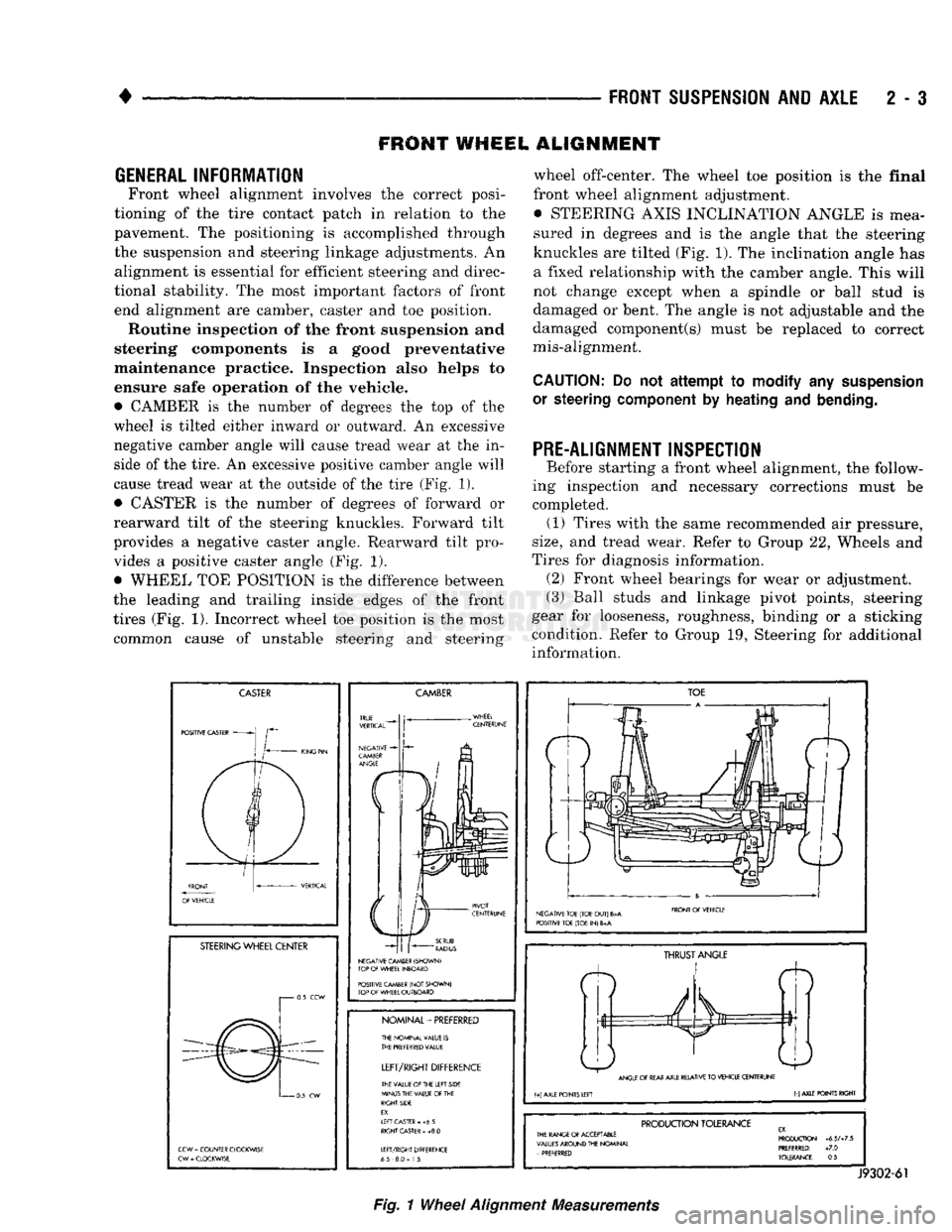
• CAMBER
is the
number
of
degrees
the top of the
wheel
is
tilted either inward
or
outward.
An
excessive
negative camber angle will cause tread wear
at the in
side
of
the tire.
An
excessive positive camber angle will
cause tread wear
at the
outside
of
the tire (Fig.
1),
• CASTER
is the
number
of
degrees
of
forward
or
rearward tilt
of the
steering knuckles. Forward tilt
provides
a
negative caster angle. Rearward tilt pro vides
a
positive caster angle
(Fig. 1).
• WHEEL
TOE
POSITION
is the
difference between
the leading
and
trailing inside edges
of the
front
tires (Fig.
1).
Incorrect wheel
toe
position
is the
most common cause
of
unstable steering
and
steering wheel off-center.
The
wheel
toe
position
is the
final
front wheel alignment adjustment. • STEERING AXIS INCLINATION ANGLE
is
mea
sured
in
degrees
and is the
angle that
the
steering
knuckles
are
tilted (Fig. 1).
The
inclination angle
has
a fixed relationship with
the
camber angle. This will
not change except when
a
spindle
or
ball stud
is
damaged
or
bent.
The
angle
is not
adjustable
and the
damaged component(s) must
be
replaced
to
correct
mis-alignment.
CAUTION:
Do not
attempt to modify
any
suspension
or steering
component
by
heating
and
bending.
PRE-ALIGNMENT INSPECTION
Before starting
a
front wheel alignment,
the
follow
ing inspection
and
necessary corrections must
be
completed.
(1)
Tires with
the
same recommended
air
pressure,
size,
and
tread wear. Refer
to
Group
22,
Wheels
and
Tires
for
diagnosis information. (2) Front wheel bearings
for
wear
or
adjustment.
(3) Ball studs
and
linkage pivot points, steering
gear
for
looseness, roughness, binding
or a
sticking
condition. Refer
to
Group
19,
Steering
for
additional information.
CASTER
POSITIVE CASTER
STEERING
WHEEL CENTER
i 0.5
CCW
0
5
CW
CCW
=
COUNTER CLOCKWISE
CW
-
CLOCKWISE
CAMBER
NEGATIVE CAMBER (SHOWN)
TOP
OF
WHEEL INBOARD
POSITIVE CAMBER
(NOT
SHOWN)
TOP
OF
WHEEL OUTBOARD
NOMINAL-PREFERRED
THE NOMINAL VALUE
IS
THE
PREFERRED
VALUE
LEFT/RIGHT
DIFFERENCE
THE VALUE
Of
THE LEFT SIDE
MINUS THE VALUE
OF
THE
RIGHT SIDE
EX.
If
FT CASTER
- +6 5
RIGHT
CASTER
»
+8.0
LEFT/RIGHT DIFFERENCE
65 8.0
=
1
5
TOE
NEGATIVE TOE (TOE
OUT)
B>A
POSITIVE TOE (TOE
IN) 6
FRONT
Of
VEHICLE
ft
THRUST
ANGLE
ANGLE
OF
REAR
AXLE RELATIVE
TO
VEHICLE CENTERUNE
(+)
AXLE POINTS LEFT
(-)
AXLE POINTS RIGHT
PRODUCTION
TOLERANCE
THE RANGE
Of
ACCEPTABLE
VALUES
AROUND THE NOMINAL
-
PREFERRED PRODUCTION
+6.5A7.5
PREFERRED:
+7.0
TOLERANCE:
0.5
J9302-61
Fig.
1
Wheel
Alignment
Measurements
Page 64 of 1502
•
FRONT
SUSPENSION
AND
AXLE
2 - 11 (2) Position the seal over the ball stud (if neces
sary, use a replacement seal). Force portion of the
seal downward on the ball stud housing with an ap
propriate size socket wrench until it is securely locked in place.
(3) Install lower suspension arm using procedure
under Lower Suspension Arm Installation.
LOWER SUSPENSION
ARM
BUSHING
REMOVAL (1) Follow procedure under Coil Spring and Lower
Suspension Arm Removal.
(2) Use an arbor press and an appropriate size
sleeve to force the original bushing from the lower
suspension arm bore.
INSTALLATION (1) Use an arbor press and an appropriate size
sleeve to force the replacement bushing into the
lower suspension arm bore. Ensure that it is com
pletely seated in the bore.
(2) Install the lower suspension arm according to in
structions provided within the installation procedure.
UPPER SUSPENSION
ARM REMOVAL (1) Raise the vehicle. Position support stands un
der the frame rail and lower the front of the hoist.
Remove the wheel/tire.
(2) Remove shock absorber, refer to above proce
dures.
(3) Install Spring Compressor DD-1278 (Fig. 5).
Tighten the nut finger-tight and then loosen it 1/2 of- a-turn.
(4) Remove the cotter pins and the ball stud nuts.
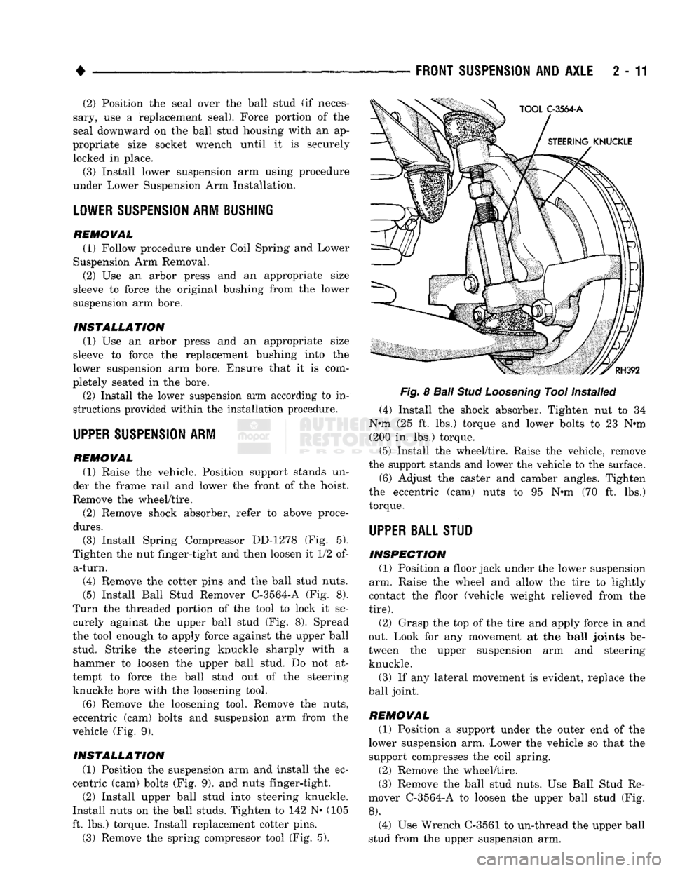
(5) Install Ball Stud Remover C^3564-A (Fig. 8).
Turn the threaded portion of the tool to lock it se curely against the upper ball stud (Fig. 8). Spread
the tool enough to apply force against the upper ball stud. Strike the steering knuckle sharply with a
hammer to loosen the upper ball stud. Do not at
tempt to force the ball stud out of the steering knuckle bore with the loosening tool.
(6) Remove the loosening tool. Remove the nuts,
eccentric (cam) bolts and suspension arm from the
vehicle (Fig. 9).
INSTALLATION (1) Position the suspension arm and install the ec
centric (cam) bolts (Fig. 9). and nuts finger-tight.
(2) Install upper ball stud into steering knuckle.
Install nuts on the ball studs. Tighten to 142 N« (105
ft. lbs.) torque. Install replacement cotter pins.
(3) Remove the spring compressor tool (Fig. 5).
Fig.
8
Ball
Stud
Loosening
Tool Installed
(4) Install the shock absorber. Tighten nut to 34
N*m (25 ft. lbs.) torque and lower bolts to 23 N*m (200 in. lbs.) torque.
(5) Install the wheel/tire. Raise the vehicle, remove
the support stands and lower the vehicle to the surface.
(6) Adjust the caster and camber angles. Tighten
the eccentric (cam) nuts to 95 N*m (70 ft. lbs.)
torque.
UPPER BALL STUD
INSPECTION (1) Position a floor jack under the lower suspension
arm. Raise the wheel and allow the tire to lightly
contact the floor (vehicle weight relieved from the
tire).
(2) Grasp the top of the tire and apply force in and
out. Look for any movement at the ball joints be
tween the upper suspension arm and steering knuckle.
(3) If any lateral movement is evident, replace the
ball joint.
REMOVAL (1) Position a support under the outer end of the
lower suspension arm. Lower the vehicle so that the
support compresses the coil spring.
(2) Remove the wheel/tire.
(3) Remove the ball stud nuts. Use Ball Stud Re
mover C-3564-A to loosen the upper ball stud (Fig.
8).
(4) Use Wrench C-3561 to un-thread the upper ball
stud from the upper suspension arm.
Page 230 of 1502
•
BRAKES
5 - 43
CAMPER
ASSEMBLY
(1) Mount caliper in vise equipped with protective
jaws.
Do not overtighten vise. Excessive pressure could cause bore distortion and piston binding. (2) Lubricate new piston seal and piston bore with
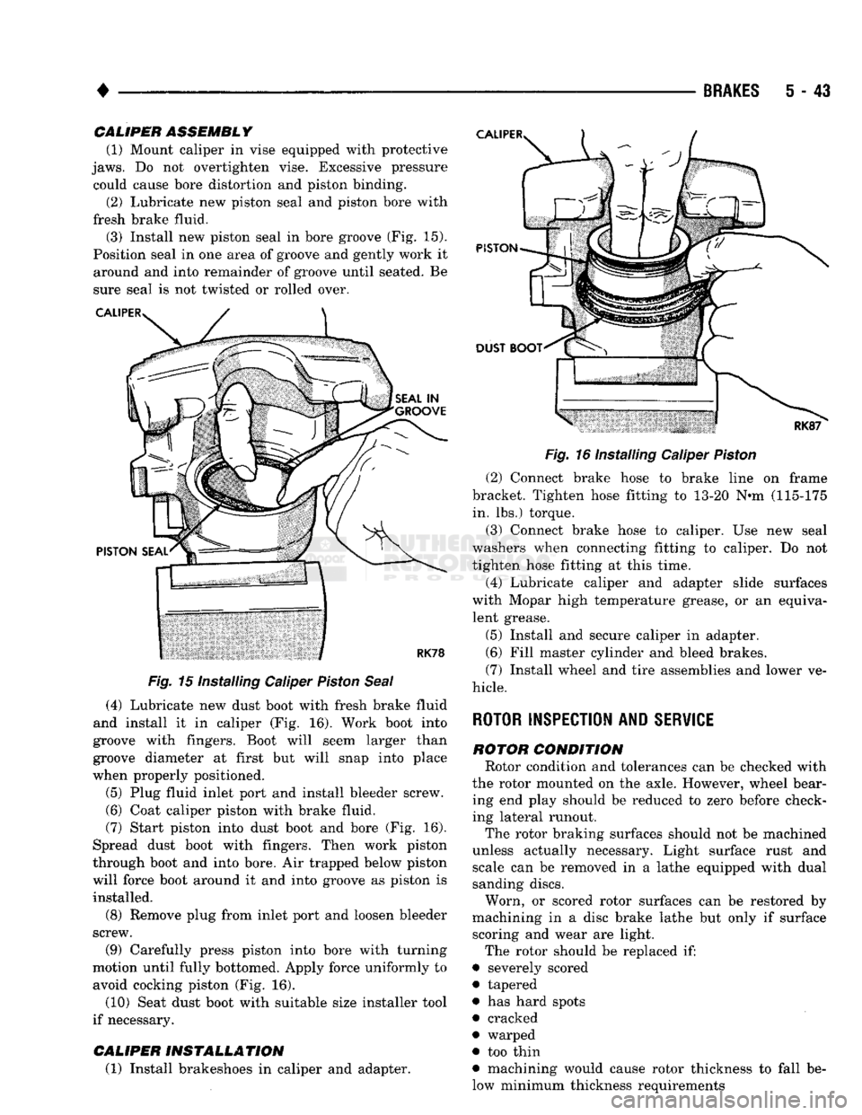
fresh brake fluid. (3) Install new piston seal in bore groove (Fig. 15).
Position seal in one area of groove and gently work it around and into remainder of groove until seated. Be
sure seal is not twisted or rolled over.
Fig.
15 Installing Caliper
Piston
Seal
(4) Lubricate new dust boot with fresh brake fluid
and install it in caliper (Fig. 16). Work boot into
groove with fingers. Boot will seem larger than
groove diameter at first but will snap into place
when properly positioned.
(5) Plug fluid inlet port and install bleeder screw. (6) Coat caliper piston with brake fluid.
(7) Start piston into dust boot and bore (Fig. 16).
Spread dust boot with fingers. Then work piston
through boot and into bore. Air trapped below piston
will force boot around it and into groove as piston is installed.
(8) Remove plug from inlet port and loosen bleeder
screw.
(9) Carefully press piston into bore with turning
motion until fully bottomed. Apply force uniformly to avoid cocking piston (Fig. 16).
(10) Seat dust boot with suitable size installer tool
if necessary.
CALIPER
INSTALLATION
(1) Install brakeshoes in caliper and adapter.
Fig.
16 Installing Caliper
Piston
(2) Connect brake hose to brake line on frame
bracket. Tighten hose fitting to 13-20 N«m (115-175 in. lbs.) torque.
(3) Connect brake hose to caliper. Use new seal
washers when connecting fitting to caliper. Do not
tighten hose fitting at this time.
(4) Lubricate caliper and adapter slide surfaces
with Mopar high temperature grease, or an equiva lent grease.
(5) Install and secure caliper in adapter.
(6) Fill master cylinder and bleed brakes.
(7) Install wheel and tire assemblies and lower ve
hicle.
ROTOR INSPECTION AND
SERVICE
ROTOR
CONDITION
Rotor condition and tolerances can be checked with
the rotor mounted on the axle. However, wheel bear ing end play should be reduced to zero before check
ing lateral runout.
The rotor braking surfaces should not be machined
unless actually necessary. Light surface rust and scale can be removed in a lathe equipped with dual
sanding discs.
Worn, or scored rotor surfaces can be restored by
machining in a disc brake lathe but only if surface scoring and wear are light.
The rotor should be replaced if:
• severely scored
• tapered
• has hard spots
• cracked
• warped
• too thin
• machining would cause rotor thickness to fall be
low minimum thickness requirements
Page 235 of 1502
5
- 48
BRAKES
•
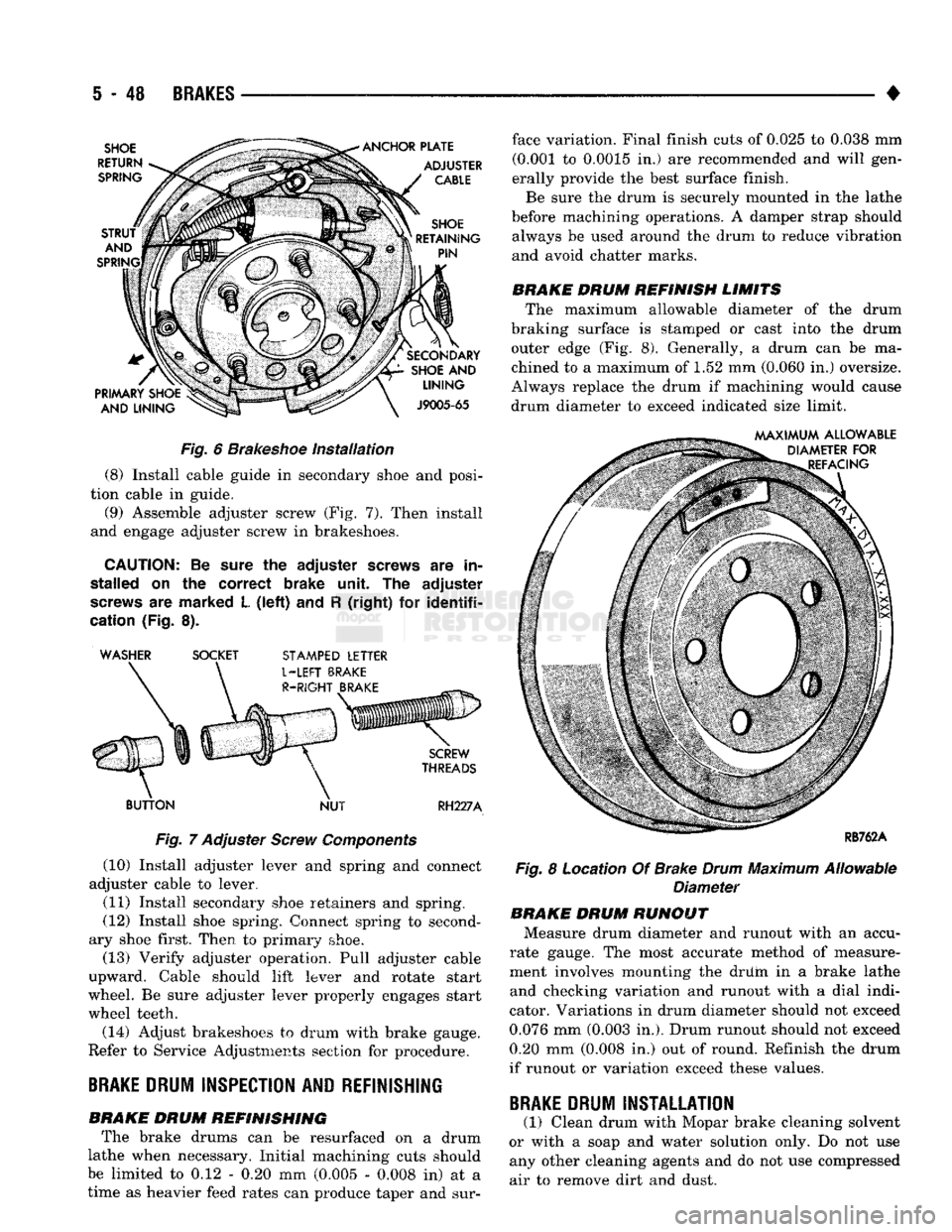
Fig.
6
Brakeshoe
Installation
(8) Install cable guide in secondary shoe and posi
tion cable in guide. (9) Assemble adjuster screw (Fig. 7). Then install
and engage adjuster screw in brakeshoes.
CAUTION:
Be sure the
adjuster
screws
are in
stalled
on the
correct
brake unit. The
adjuster
screws
are marked L
(left)
and R
(right)
for
identifi
cation
(Fig. 8). ' WASHER SOCKET
STAMPED
LETTER
BUTTON
NUT
RH227A
Fig.
7 Adjuster
Screw
Components
(10) Install adjuster lever and spring and connect
adjuster cable to lever.
(11) Install secondary shoe retainers and spring.
(12) Install shoe spring. Connect spring to second
ary shoe first. Then to primary shoe. (13) Verify adjuster operation. Pull adjuster cable
upward. Cable should lift lever and rotate start
wheel. Be sure adjuster lever properly engages start
wheel teeth.
(14) Adjust brakeshoes to drum with brake gauge.
Refer to Service Adjustments section for procedure.
BRAKE
DRUM
INSPECTION
AND
REFINISHING
BRAKE DRUM REFINISHING The brake drums can be resurfaced on a drum
lathe when necessary. Initial machining cuts should
be limited to 0.12 - 0.20 mm (0.005 - 0.008 in) at a
time as heavier feed rates can produce taper and sur face variation. Final finish cuts of 0.025 to 0.038 mm
(0.001 to 0.0015 in.) are recommended and will gen
erally provide the best surface finish.
Be sure the drum is securely mounted in the lathe
before machining operations. A damper strap should always be used around the drum to reduce vibration
and avoid chatter marks.
BRAKE DRUM REFINISH LIMITS The maximum allowable diameter of the drum
braking surface is stamped or cast into the drum outer edge (Fig. 8). Generally, a drum can be ma
chined to a maximum of 1.52 mm (0.060 in.) oversize.
Always replace the drum if machining would cause
drum diameter to exceed indicated size limit.
Fig.
8 Location Of Brake
Drum
Maximum Allowable
Diameter BRAKE DRUM RUNOUT
Measure drum diameter and runout with an accu
rate gauge. The most accurate method of measure
ment involves mounting the driim in a brake lathe
and checking variation and runout with a dial indi
cator. Variations in drum diameter should not exceed
0.076 mm (0.003 in.). Drum runout should not exceed 0.20 mm (0.008 in.) out of round. Refinish the drum
if runout or variation exceed these values.
BRAKE
DRUM
INSTALLATION
(1) Clean drum with Mopar brake cleaning solvent
or with a soap and water solution only. Do not use any other cleaning agents and do not use compressed
air to remove dirt and dust.
Page 241 of 1502
5
- 54
BRAKES
• (11) Attach adjuster cable to adjuster lever. Be
sure cable is properly routed.
(12) Adjust brakeshoes to drum with brake gauge.
BRAKE
DRUM INSTALLATION
(1) Position drum on axle housing.
(2) Install bearing and inner nut. Adjust bearing
as described in Group 3. (3) Install locking washer and outer nut. Bend
locking washer to secure it. (4) Place new gasket on hub and install axle shaft,
cones,
lock washers and nuts. (5) Install wheel and tire assembly.
(6) Remove support stands and lower vehicle.
BRAKE
DRUM
SERVICE
BRAKE DRUM REFINISHING The brake drums can be resurfaced on a drum
lathe when necessary. Initial machining cuts should
be limited to 0.12 - 0.20 mm (0.005 - 0.008 in.) at a time as heavier feed rates can produce taper and sur
face variation. Final finish cuts of 0.025 to 0.38 mm (0.001 to 0.0015 in) are recommended and will gen
erally provide the best surface finish.
Be sure the drum is securely mounted in the lathe
before machining operations. A damper strap should always be used around the drum to reduce vibration
and avoid chatter marks.
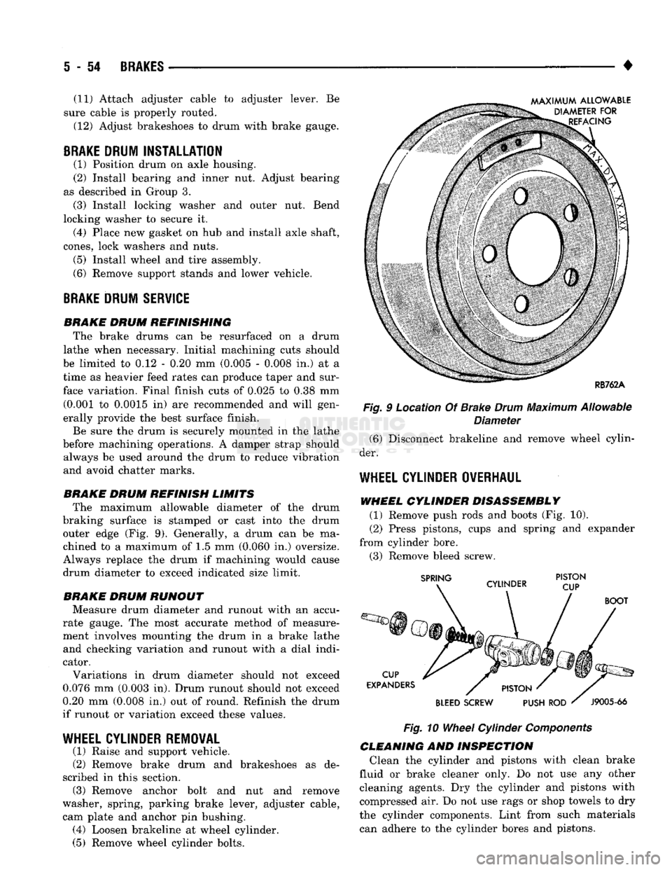
BRAKE DRUM REFINISH LIMITS The maximum allowable diameter of the drum
braking surface is stamped or cast into the drum outer edge (Fig. 9). Generally, a drum can be ma
chined to a maximum of 1.5 mm (0.060 in.) oversize.
Always replace the drum if machining would cause
drum diameter to exceed indicated size limit.
BRAKE DRUM RUNOUT Measure drum diameter and runout with an accu
rate gauge. The most accurate method of measure
ment involves mounting the drum in a brake lathe and checking variation and runout with a dial indi
cator.
Variations in drum diameter should not exceed
0.076 mm (0.003 in). Drum runout should not exceed
0.20 mm (0.008 in.) out of round. Refinish the drum
if runout or variation exceed these values.
WHEEL
CYLINDER REMOVAL
(1) Raise and support vehicle.
(2) Remove brake drum and brakeshoes as de
scribed in this section. (3) Remove anchor bolt and nut and remove
washer, spring, parking brake lever, adjuster cable, cam plate and anchor pin bushing. (4) Loosen brakeline at wheel cylinder.
(5) Remove wheel cylinder bolts. Fig. 9 Location Of Brake
Drum
Maximum Allowable
Diameter (6) Disconnect brakeline and remove wheel cylin
der.
WHEEL
CYLINDER OVERHAUL
WHEEL CYLINDER DISASSEMBLY (1) Remove push rods and boots (Fig. 10).
(2) Press pistons, cups and spring and expander
from cylinder bore. (3) Remove bleed screw.
Fig.
10
Wheel
Cylinder
Components
CLEANING AND INSPECTION Clean the cylinder and pistons with clean brake
fluid or brake cleaner only. Do not use any other cleaning agents. Dry the cylinder and pistons with
compressed air. Do not use rags or shop towels to dry
the cylinder components. Lint from such materials can adhere to the cylinder bores and pistons.
Page 256 of 1502
•
CLUTCH
6 - 3 Check condition of the clutch before installation. A
warped cover or diaphragm spring will cause grab and incomplete release or engagement.
Be careful when handling the cover and disc. Im
pact can distort the cover, diaphragm spring, release
fingers and the hub of the clutch disc.
Use an alignment tool when positioning the disc on
the flywheel. The tool prevents accidental misalign ment which could result in cover distortion and disc
damage.
A frequent cause of clutch cover distortion (and
consequent misalignment) is improper bolt tighten
ing. To avoid warping the cover, tighten the bolts al
ternately (in a diagonal pattern) and evenly (2-3
threads at a time) to specified torque.
Clutch
Housing
Misalignment And Runout Clutch housing alignment is important to proper
operation. The housing bore maintains alignment be
tween the crankshaft and transmission input shaft.
Misalignment can cause noise, incomplete clutch
release and chatter. It can also result in premature
wear of the pilot bearing, cover release fingers and
clutch disc. In severe cases, misalignment can also cause premature wear of the transmission input
shaft and bearing.
Housing face misalignment is generally caused by
incorrect seating on the engine or transmission, loose
housing bolts, missing alignment dowels or housing damage. Infrequently, misalignment may also be
caused by housing mounting surfaces that are not
parallel. If housing misalignment is suspected, housing bore
and face runout can be checked with a dial indicator
as described in the following two procedures:
MEASURING
CLUTCH HOUSING BORE
RUNOUT
(1) Remove the clutch housing and strut.
(2) Remove the clutch cover and disc.
(3) Replace one of the flywheel bolts with a 7/16-20
threaded rod that is 10 in. (25.4 cm) long (Fig. 1).
The rod will be used to mount the dial indicator.
(4) Remove the release fork from the clutch hous
ing. (5) Reinstall the clutch housing. Tighten the hous
ing bolts nearest the alignment dowels first. (6) Mount the dial indicator on the threaded rod
and position the indicator plunger on the surface of
the clutch housing bore (Fig. 2).
(7) Rotate the crankshaft until the indicator
plunger is at the top center of the housing bore. Zero the indicator at this point.
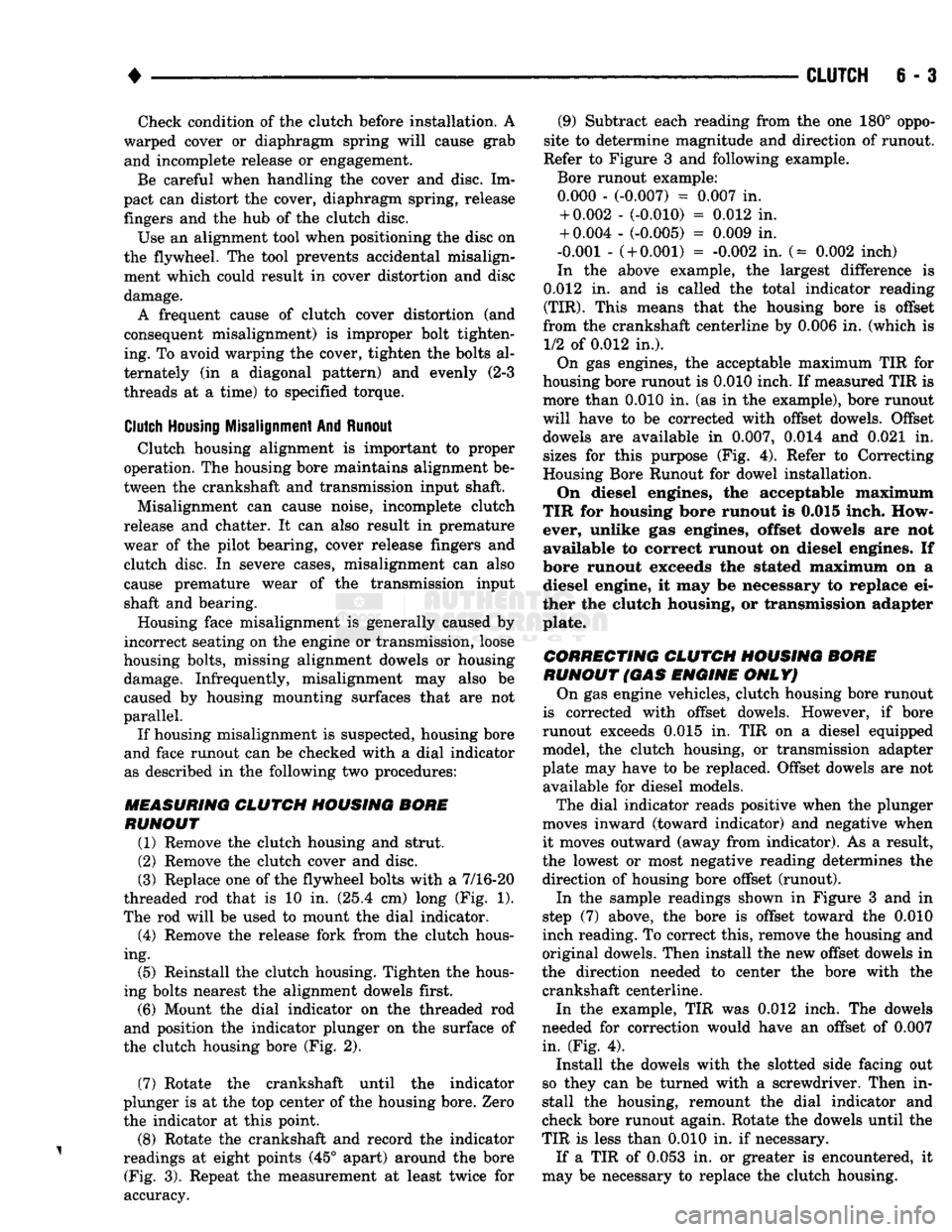
(8) Rotate the crankshaft and record the indicator
readings at eight points (45° apart) around the bore (Fig. 3). Repeat the measurement at least twice for
accuracy. (9) Subtract each reading from the one 180° oppo
site to determine magnitude and direction of runout.
Refer to Figure 3 and following example.
Bore runout example: 0.000 - (-0.007) = 0.007 in. + 0.002 - (-0.010) = 0.012 in.
+ 0.004 - (-0.005) = 0.009 in.
-0.001 -
(
+ 0.001) = -0.002 in. (= 0.002 inch)
In the above example, the largest difference is
0.012 in. and is called the total indicator reading
(TIR).
This means that the housing bore is offset
from the crankshaft centerline by 0.006 in. (which is 1/2 of 0.012 in.).
On gas engines, the acceptable maximum TIR for
housing bore runout is 0.010 inch. If measured TIR is more than 0.010 in. (as in the example), bore runout
will have to be corrected with offset dowels. Offset dowels are available in 0.007, 0.014 and 0.021 in.
sizes for this purpose (Fig. 4). Refer to Correcting
Housing Bore Runout for dowel installation.
On diesel engines, the acceptable maximum
TIR for housing bore runout is 0.015 inch. How
ever, unlike gas engines, offset dowels are not available to correct runout on diesel engines. If
bore runout exceeds the stated maximum on a diesel engine, it may be necessary to replace ei
ther the clutch housing, or transmission adapter
plate.
CORRECTING CLUTCH HOUSING BORE
RUNOUT
(GAS
ENGINE
ONLY)
On gas engine vehicles, clutch housing bore runout
is corrected with offset dowels. However, if bore
runout exceeds 0.015 in. TIR on a diesel equipped model, the clutch housing, or transmission adapter
plate may have to be replaced. Offset dowels are not available for diesel models.
The dial indicator reads positive when the plunger
moves inward (toward indicator) and negative when it moves outward (away from indicator). As a result,
the lowest or most negative reading determines the
direction of housing bore offset (runout).
In the sample readings shown in Figure 3 and in
step (7) above, the bore is offset toward the 0.010
inch reading. To correct this, remove the housing and
original dowels. Then install the new offset dowels in
the direction needed to center the bore with the crankshaft centerline.
In the example, TIR was 0.012 inch. The dowels
needed for correction would have an offset of 0.007
in. (Fig. 4).
Install the dowels with the slotted side facing out
so they can be turned with a screwdriver. Then in
stall the housing, remount the dial indicator and
check bore runout again. Rotate the dowels until the
TIR is less than 0.010 in. if necessary.
If a TIR of 0.053 in. or greater is encountered, it
may be necessary to replace the clutch housing.
Page 258 of 1502
•
CLUTCH
6 - 5
INDICATOR
PLUNGER
DIAL INDICATOR
CLUTCH
HOUSING
FACE
INDICATOR MOUNTING
„
STUD OR ROD
J9006-29
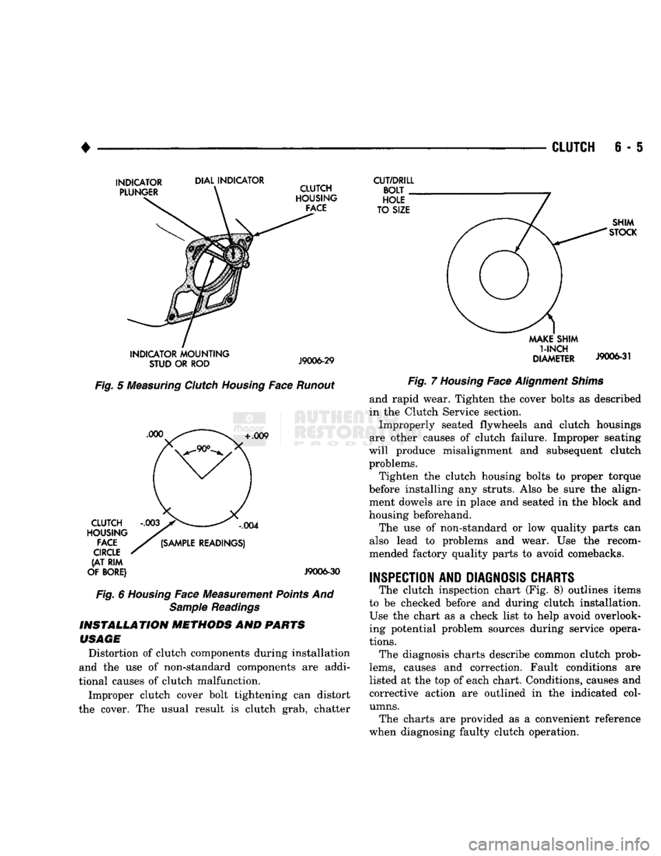
Fig.
5
Measuring
Clutch
Housing
Face
Runout
+
.009 CLUTCH
HOUSING
FACE
CIRCLE
(AT RIM
OF BORE)
,004
(SAMPLE
READINGS)
J9006-30
Fig.
6
Housing
Face Measurement
Points
And
Sample
Readings
INSTALLATION
METHODS
AND
PARTS
USAGE
Distortion of clutch components during installation
and the use of non-standard components are addi
tional causes of clutch malfunction.
Improper clutch cover bolt tightening can distort
the cover. The usual result is clutch grab, chatter
CUT/DRILL
BOLT
HOLE
TO SIZE SHIM
STOCK
MAKE
SHIM
1-INCH
DIAMETER
J9006-31
Fig.
7
Housing
Face
Alignment
Shims
and rapid wear. Tighten the cover bolts as described
in the Clutch Service section.
Improperly seated flywheels and clutch housings
are other causes of clutch failure. Improper seating
will produce misalignment and subsequent clutch problems.
Tighten the clutch housing bolts to proper torque
before installing any struts. Also be sure the align ment dowels are in place and seated in the block and
housing beforehand.
The use of non-standard or low quality parts can
also lead to problems and wear. Use the recom
mended factory quality parts to avoid comebacks.
INSPECTION AND DIAGNOSIS CHARTS
The clutch inspection chart (Fig. 8) outlines items
to be checked before and during clutch installation. Use the chart as a check list to help avoid overlooking potential problem sources during service opera
tions.
The diagnosis charts describe common clutch prob
lems,
causes and correction. Fault conditions are
listed at the top of each chart. Conditions, causes and
corrective action are outlined in the indicated col
umns.
The charts are provided as a convenient reference
when diagnosing faulty clutch operation.
Page 259 of 1502
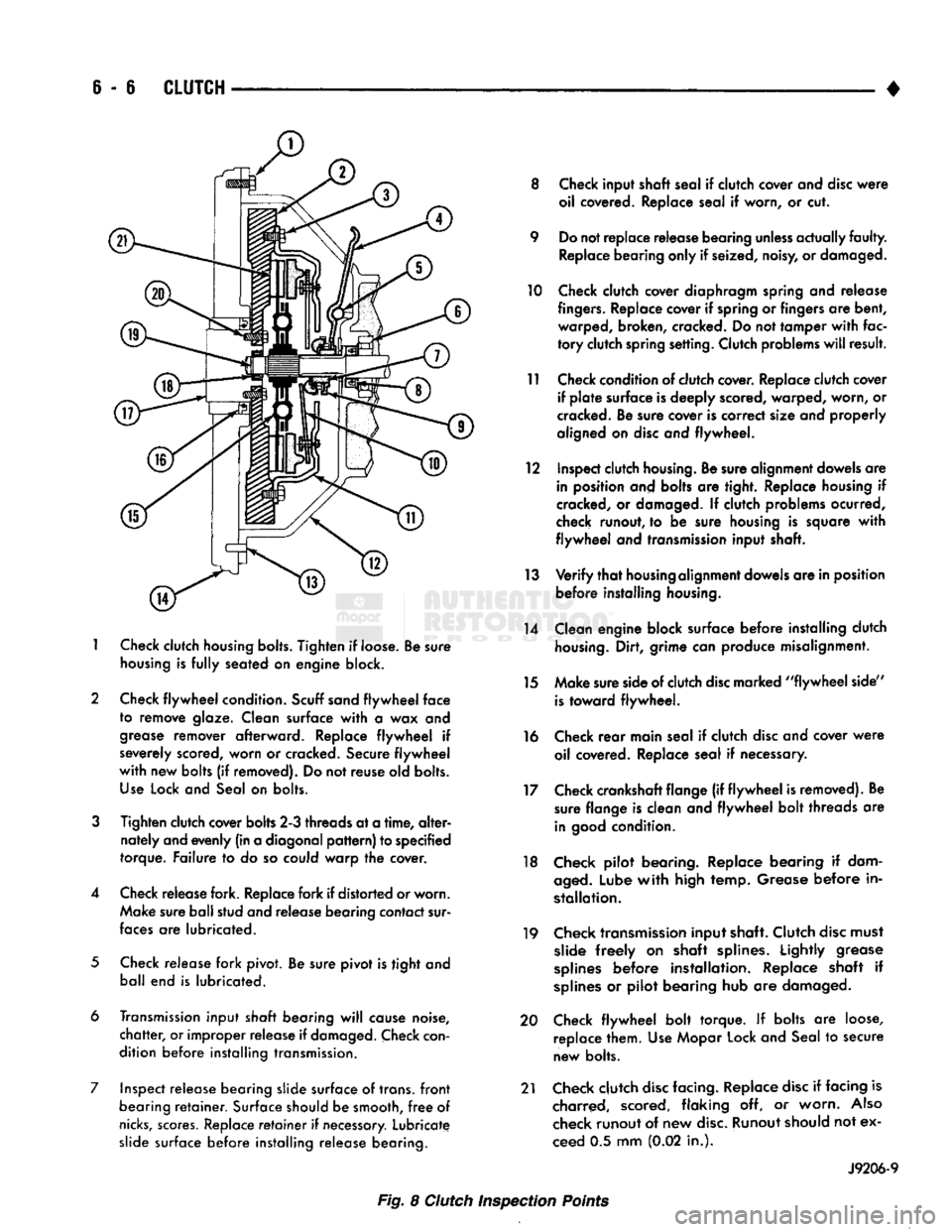
6 - 6
CLUTCH
1
Check
clutch
housing bolts.
Tighten
if loose. Be sure
housing
is
fully
seated on engine block.
2 Check
flywheel
condition.
Scuff sand
flywheel
face
to remove glaze. Clean surface
with
a wax and
grease
remover afterward. Replace
flywheel
if
severely scored, worn or cracked. Secure
flywheel
with
new bolts (if removed). Do not reuse old bolts.
Use
Lock and Seal on bolts.
3
Tighten clutch cover bolts 2-3 threads at a
time,
alter
nately and evenly (in a diagonal
pattern)
to specified
torque. Failure to do so could warp the cover.
4 Check release fork. Replace fork if distorted or worn. Make sure ball stud and release bearing contact sur
faces
are lubricated.
5
Check release fork pivot. Be sure pivot is tight and ball end is lubricated.
6 Transmission input
shaft
bearing
will
cause noise,
chatter,
or improper release if
damaged.
Check
con
dition before installing transmission.
7 Inspect release bearing slide surface of trans,
front
bearing
retainer.
Surface should be smooth,
free
of
nicks,
scores.
Replace
retainer
if
necessary.
Lubricate slide surface before installing release bearing. 8 Check input shaft seal if clutch cover and
disc
were
oil covered. Replace seal if worn, or cut.
9 Do not replace release bearing
unless
actually
faulty.
Replace bearing only if seized, noisy, or damaged.
10 Check clutch cover diaphragm spring and release
fingers.
Replace cover if spring or fingers are bent, warped, broken, cracked. Do not tamper
with
fac
tory
clutch spring setting. Clutch problems
will
result.
11 Check condition of clutch cover. Replace clutch cover if
plate
surface is deeply scored, warped, worn, or
cracked. Be sure cover is correct size and properly
aligned on
disc
and flywheel.
12 Inspect clutch
housing.
Be sure alignment dowels are in position and bolts are tight. Replace housing if
cracked, or damaged. If clutch problems ocurred,
check runout, to be sure housing is square
with
flywheel
and transmission input shaft.
13
Verify
that
housing
alignment dowels are in position before installing
housing.
14 Clean engine block surface before installing clutch
housing.
Dirt, grime can produce misalignment.
15 Make sure side of clutch
disc
marked
"flywheel
side"
is
toward flywheel.
16 Check
rear
main seal if clutch
disc
and cover
were
oil covered. Replace seal if necessary.
17 Check crankshaft flange (if
flywheel
is removed). Be sure flange is clean and
flywheel
bolt threads are
in
good
condition.
18 Check pilot bearing. Replace bearing if dam
aged.
Lube
with
high temp. Grease before in
stallation.
19 Check transmission input shaft. Clutch
disc
must slide
freely
on shaft splines. Lightly grease
splines
before installation. Replace shaft if
splines
or pilot bearing hub are damaged.
20 Check
flywheel
bolt torque. If bolts are loose, replace them. Use Mopar Lock and Seal to secure
new bolts.
21 Check clutch
disc
facing. Replace
disc
if facing is charred, scored, flaking off, or worn.
Also
check runout of new
disc.
Runout should not ex
ceed 0.5 mm (0.02 in.).
J9206-9
Fig. 8 Clutch Inspection Points
Page 612 of 1502
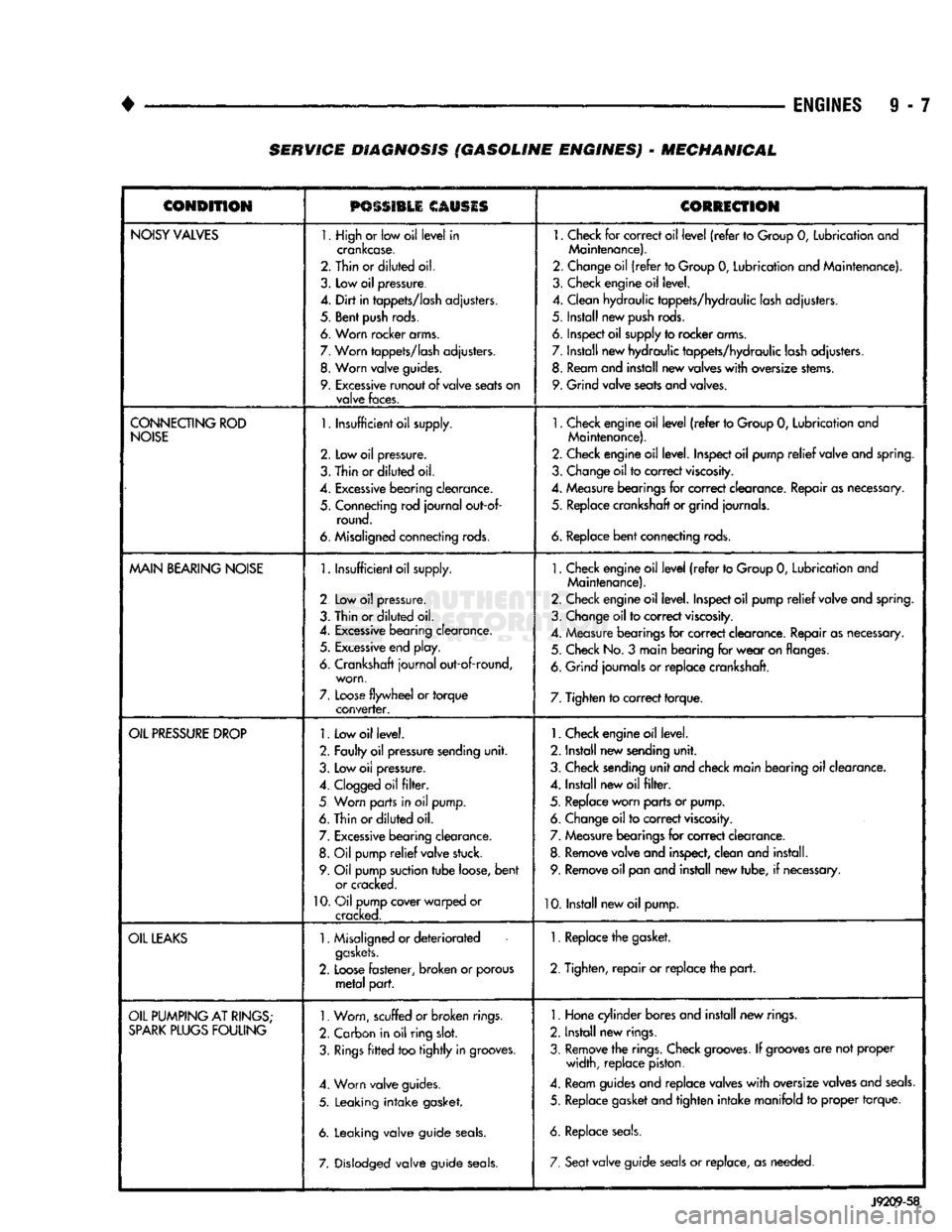
•
ENGINES
9 - 7 SERVICE DIAGNOSIS (GASOLINE ENGINES) - MECHANICAL
CONDITION
PSSSI1LI
CAUSIS
CORRECTION
NOISY
VALVES
1. High
or
low oil
level
in
crankcase.
2. Thin or
diluted
oil.
3.
Low
oil
pressure.
4.
Dirt
in
tappets/lash
adjusters.
5. Bent
push
rods.
6. Worn rocker arms.
7.
Worn
tappets/lash
adjusters.
8.
Worn
valve
guides.
9.
Excessive
runout
of
valve
seats
on
valve
faces.
1.
Check
for
correct oil
level
(refer
to
Group
0,
Lubrication and
Maintenance).
2. Change oil
(refer
to Group
0,
Lubrication and Maintenance).
3. Check engine oil level.
4. Clean hydraulic tappets/hydraulic lash adjusters.
5. Install new
push
rods.
6. Inspect oil supply to rocker arms.
7. Install new hydraulic tappets/hydraulic lash adjusters. 8. Ream and install new valves
with
oversize stems.
9. Grind valve seats and valves.
CONNECTING
ROD
NOISE
1.
Insufficient oil supply.
2.
Low oil
pressure.
3.
Thin
or
diluted
oil.
4.
Excessive
bearing
clearance.
5. Connecting rod
journal
out-of- round.
6. Misaligned connecting rods.
1.
Check engine oil
level
(refer
to Group
0,
Lubrication and
Maintenance).
2. Check engine oil level. Inspect oil pump
relief
valve and spring.
3. Change oil to correct
viscosity.
4. Measure bearings for correct clearance. Repair as necessary, 5. Replace crankshaft or grind journals.
6.
Replace
bent
connecting rods.
MAIN
BEARING
NOISE
1.
Insufficient oil supply.
2 Low
oil
pressure.
3. Thin or
diluted
oil.
4.
Excessive
bearing clearance. 5.
Excessive
end play.
6. Crankshaft
journal
out-of-round, worn,
7.
Loose
flywheel
or
torque
converter.
1.
Check engine oil
level
(refer
to Group
0,
Lubrication and
Maintenance).
2. Check engine oil level. Inspect oil pump
relief
valve and spring.
3. Change oil to correct
viscosity.
4. Measure bearings for correct clearance. Repair as necessary. 5. Check No.
3
main bearing for
wear
on flanges.
6. Grind journals
or
replace crankshaft.
7. Tighten to correct torque.
OIL
PRESSURE
DROP
1.
Low oil level.
2. Faulty oil pressure sending
unit.
3. Low
oil
pressure.
4.
Clogged
oil
filter.
5 Worn parts in
oil
pump.
6. Thin or
diluted
oil.
7.
Excessive
bearing clearance. 8.
Oil
pump
relief
valve stuck.
9. Oil pump suction
tube
loose,
bent
or cracked.
10.
Oil pump cover warped
or
cracked.
1.
Check engine oil level.
2. Install new sending
unit.
3. Check sending
unit
and check main bearing oil clearance.
4. Install new oil
filter.
5. Replace worn parts or pump. 6. Change oil to correct
viscosity.
7. Measure bearings for correct clearance.
8. Remove valve and inspect, clean and install. 9. Remove oil pan and install new tube,
if
necessary.
10. Install new oil pump.
OIL
LEAKS
1.
Misaligned or
deteriorated
gaskets.
2.
Loose
fastener, broken
or
porous
metal
part.
1. Replace the gasket.
2. Tighten,
repair
or replace the
part.
OIL
PUMPING
AT
RINGS;
SPARK
PLUGS
FOULING
1.
Worn, scuffed
or broken
rings.
2. Carbon in oil ring
slot.
3.
Rings
fitted
too
tightly
in grooves.
4. Worn valve guides.
5. Leaking
intake
gasket.
6. Leaking valve guide
seals.
7. Dislodged valve guide
seals.
1.
Hone cylinder bores and install new rings.
2. Install new rings.
3. Remove the rings. Check
grooves.
If
grooves
are not proper width, replace piston.
4. Ream guides and replace valves
with
oversize valves and
seals.
5. Replace gasket and tighten
intake
manifold
to
proper torque.
6. Replace
seals.
7. Seat
valve guide
seals
or
replace, as needed.
J9209-58