DODGE VIPER 2010 ZB II / 2.G Owners Manual
Manufacturer: DODGE, Model Year: 2010, Model line: VIPER, Model: DODGE VIPER 2010 ZB II / 2.GPages: 315, PDF Size: 4.43 MB
Page 251 of 315
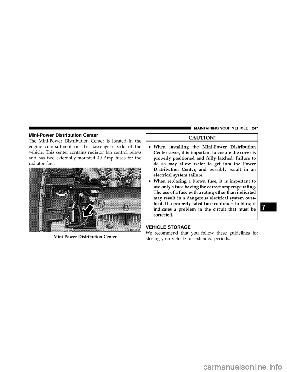
Mini-Power Distribution Center
The Mini-Power Distribution Center is located in the
engine compartment on the passenger’s side of the
vehicle. This center contains radiator fan control relays
and has two externally-mounted 40 Amp fuses for the
radiator fans.CAUTION!
•When installing the Mini-Power Distribution
Center cover, it is important to ensure the cover is
properly positioned and fully latched. Failure to
do so may allow water to get into the Power
Distribution Center, and possibly result in an
electrical system failure.
•When replacing a blown fuse, it is important to
use only a fuse having the correct amperage rating.
The use of a fuse with a rating other than indicated
may result in a dangerous electrical system over-
load. If a properly rated fuse continues to blow, it
indicates a problem in the circuit that must be
corrected.
VEHICLE STORAGE
We recommend that you follow these guidelines for
storing your vehicle for extended periods.Mini-Power Distribution Center
7
MAINTAINING YOUR VEHICLE 247
Page 252 of 315
•Fill the fuel tank. This will prevent water condensation
inside the tank. If you plan to store your vehicle more
than two months, add an anti-oxidant fuel stabilizer to
the fuel tank.
•Change the oil to remove any corrosive combustion
related acids in the crankcase.
•Check that the radiator coolant level of protection is to
at least -20°F (-29°C).
•Make sure that all tires are inflated to the optimum
pressure.
•Wash and wax the vehicle to protect the finish.
•Store the vehicle in a dry, well-ventilated location.
•Move the wiper blades away from the windshield.
•Block the wheels. Do not apply the parking brake.
•Cut blocks of plywood about the same size of the tires.
Cover each block with indoor/outdoor carpeting and
place them between the tires and concrete. This will
prevent tire flat spotting.
•For long-term storage, remove the tires and put the
vehicle up on blocks. Stack the tires on plywood and
cover with a tarp to prevent flat spotting.
•If the vehicle will be subjected to freezing tempera-
tures, either remove the battery and store it in a dry,
well ventilated area or connect a trickle charger
(1.5 Amp) with automatic shutdown / overcharge
protection to the battery. However, do not leave the
trickle charger hooked up to the battery without being
plugged in to a 110 Volt AC outlet, as this will result in
further drain on the vehicle’s battery. If the vehicle is
not going to be driven in the next three weeks, perform
the battery recharge procedure in the Service Manual.
Then, either disconnect the battery at the negative
248 MAINTAINING YOUR VEHICLE
Page 253 of 315
terminal or use the “Battery Save Feature” to conserve
battery power. Refer to “Maintenance Procedures/
Battery Save Feature” in “Maintaining Your Vehicle”
for further information.
NOTE: Disconnecting the battery causes the engine
control system to lose memory of some “learned” func-
tions. After reconnecting the battery, the engine may run
rough until the control module “relearns” these func-
tions. Using the Battery Save Feature will prevent the
engine controller from loosing its memory.
CAUTION!
Use care when disconnecting the remote positive
cable. It is connected to the battery and can short out
to any metal on the vehicle. Always tape or wrap the
exposed cable end to prevent electrical shorts. Check the battery every four to six weeks to ensure that
the voltage is above 12.40 Volts. The voltage will drop
more rapidly in hot temperatures. If battery voltage
drops below 12.40 Volts, follow the battery recharge
procedure in the Service Manual.
NOTE:
To help prevent the battery from discharging
during shorter periods of inactivity, perform the follow-
ing:
1. Make sure that the trunk/liftgate, hood, doors, win-
dows, and convertible top are completely closed.
2. Make sure that Remote Keyless Entry (RKE) transmit-
ter is operating and that the battery is good.
3. Make sure that the HOOD, TRUNK/LIFTGATE, and
DOOR switches are in adjustment. Perform the quick
system check, which follows:
Use the remote transmitter to set the alarm. If the alarm
SET light comes on and flashes, the system is operating7
MAINTAINING YOUR VEHICLE 249
Page 254 of 315
properly. If not, there is a problem with a switch or the
system. See your authorized dealer for service.
•Cover the vehicle whenever possible to prevent acci-
dental damage to the finish.
REPLACEMENT BULBS
LIGHT BULBS – InteriorBulb Number
Message Center Indicators .................. 103
Cluster ................................ 103
Gauge Pack ............................ 103
Heater Control ........................... 37
Interior Lamp ......................... 212–2
Courtesy Foot Well Lights .................. 194
Cargo Lamp (Coupe Liftgate) ................ 168LIGHT BULBS – Exterior
(Convertible Models)
Bulb Number
Low/High Beam High Intensity Discharge
(HID) Headlamp .... Serviced at authorized dealer only
Auxiliary High Beam Headlamp .....(HB3A) 9005XS
Front Park/Turn Signal Lamp .............3157AK
Fog Lamp ....................... (H10 U) 9145
Front Side Marker Lamp .................. 2886X
Center High Mounted Stop Lamp
(CHMSL) ................ 16LED (not serviceable)
Tail/Stop Lamp ......................... 3157
Taillamp ............................... 194
Rear Marker Lamp ....................... 194
Backup Lamp .......................... 3157
Rear Turn Signal Lamp .................3457AK
License Lamp ........................... 168
250 MAINTAINING YOUR VEHICLE
Page 255 of 315
LIGHT BULBS – Exterior
(Coupe Models) Bulb Number
Low/High Beam High Intensity Discharge (HID)
Headlamp......... Ser viced at authorized dealer only
Auxiliary High Beam Headlamp .....(HB3A) 9005XS
Front Park/Turn Signal Lamp .............3157AK
Fog Lamp ....................... (H10 U) 9145
Front Side Marker Lamp .................. 2886X
Center High Mounted Stop Lamp (CHMSL) . . . 16 LED
(not serviceable)
Tail/Stop/Turn Signal Lamp ................3157
Rear Marker Lamp ....................... 194
Backup Lamp .......................... 3157
License Lamp ........................... 168
NOTE: Upon turning the High Intensity Discharge
(HID) Headlamps on, there is a blue hue to the lamps.
This diminishes and becomes more white after approxi-
mately 10 seconds as the system charges.BULB REPLACEMENT
Auxiliary High Beam Headlamp, Front Park/Turn
Signal Lamp, Front Side Marker Lamp
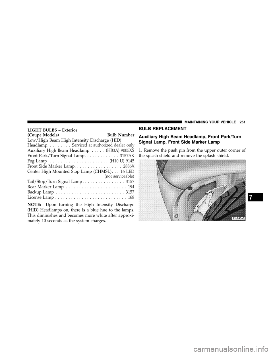
1. Remove the push pin from the upper outer corner of
the splash shield and remove the splash shield.
7
MAINTAINING YOUR VEHICLE 251
Page 256 of 315
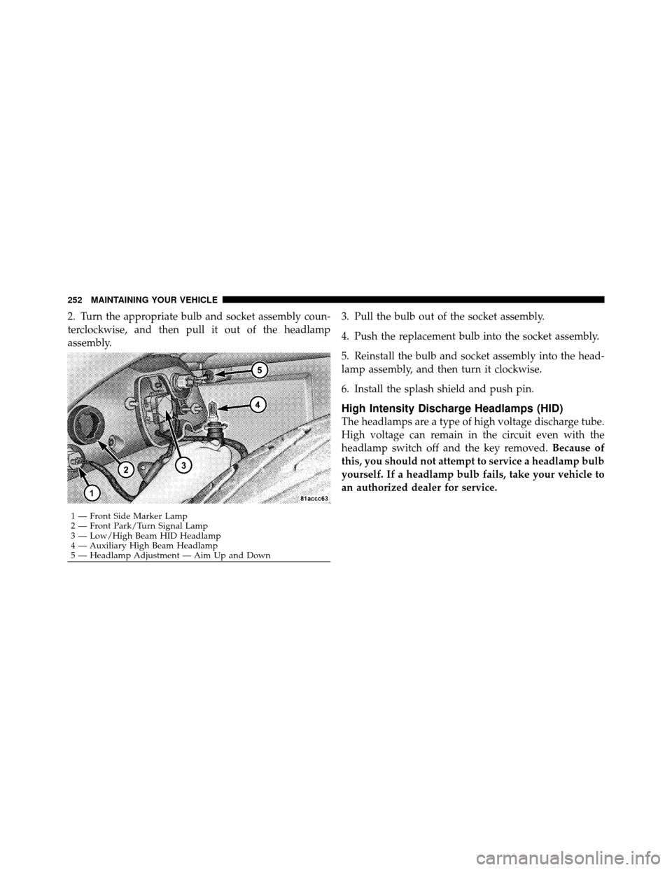
2. Turn the appropriate bulb and socket assembly coun-
terclockwise, and then pull it out of the headlamp
assembly.3. Pull the bulb out of the socket assembly.
4. Push the replacement bulb into the socket assembly.
5. Reinstall the bulb and socket assembly into the head-
lamp assembly, and then turn it clockwise.
6. Install the splash shield and push pin.
High Intensity Discharge Headlamps (HID)
The headlamps are a type of high voltage discharge tube.
High voltage can remain in the circuit even with the
headlamp switch off and the key removed.
Because of
this, you should not attempt to service a headlamp bulb
yourself. If a headlamp bulb fails, take your vehicle to
an authorized dealer for service.
1 — Front Side Marker Lamp
2 — Front Park/Turn Signal Lamp
3 — Low/High Beam HID Headlamp
4 — Auxiliary High Beam Headlamp
5 — Headlamp Adjustment — Aim Up and Down
252 MAINTAINING YOUR VEHICLE
Page 257 of 315
WARNING!
A transient high tension occurs at the bulb sockets of
High Intensity Discharge (HID) headlamps when the
headlamp switch is turned ON. It may cause serious
electrical shock or electrocution if not serviced prop-
erly. See your authorized dealer for service.
NOTE:
•When the High Intensity Discharge (HID) headlamps
are turned on, there is a blue hue to the lamps. This
diminishes and becomes more white after approxi-
mately 10 seconds as the system charges.
•If High Intensity Discharge (HID) headlamps are not
working, cycle the headlamp switch four times to see
if it will restrike.
Front Fog Lamp
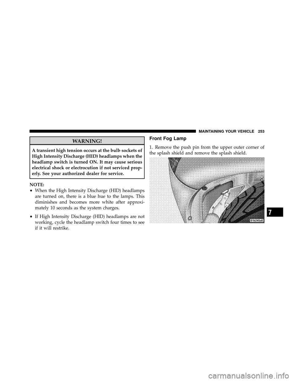
1. Remove the push pin from the upper outer corner of
the splash shield and remove the splash shield.
7
MAINTAINING YOUR VEHICLE 253
Page 258 of 315
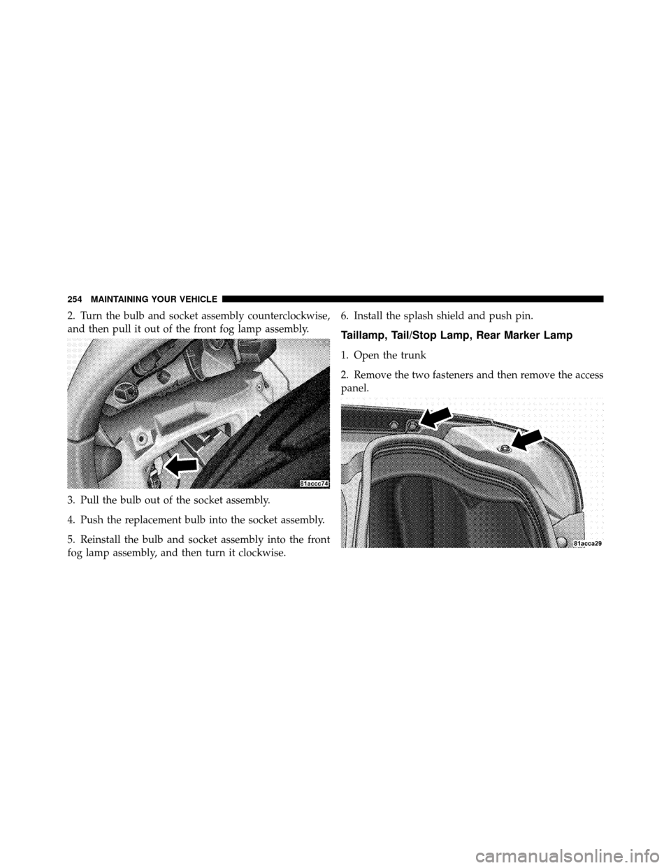
2. Turn the bulb and socket assembly counterclockwise,
and then pull it out of the front fog lamp assembly.
3. Pull the bulb out of the socket assembly.
4. Push the replacement bulb into the socket assembly.
5. Reinstall the bulb and socket assembly into the front
fog lamp assembly, and then turn it clockwise.6. Install the splash shield and push pin.
Taillamp, Tail/Stop Lamp, Rear Marker Lamp
1. Open the trunk
2. Remove the two fasteners and then remove the access
panel.
254 MAINTAINING YOUR VEHICLE
Page 259 of 315
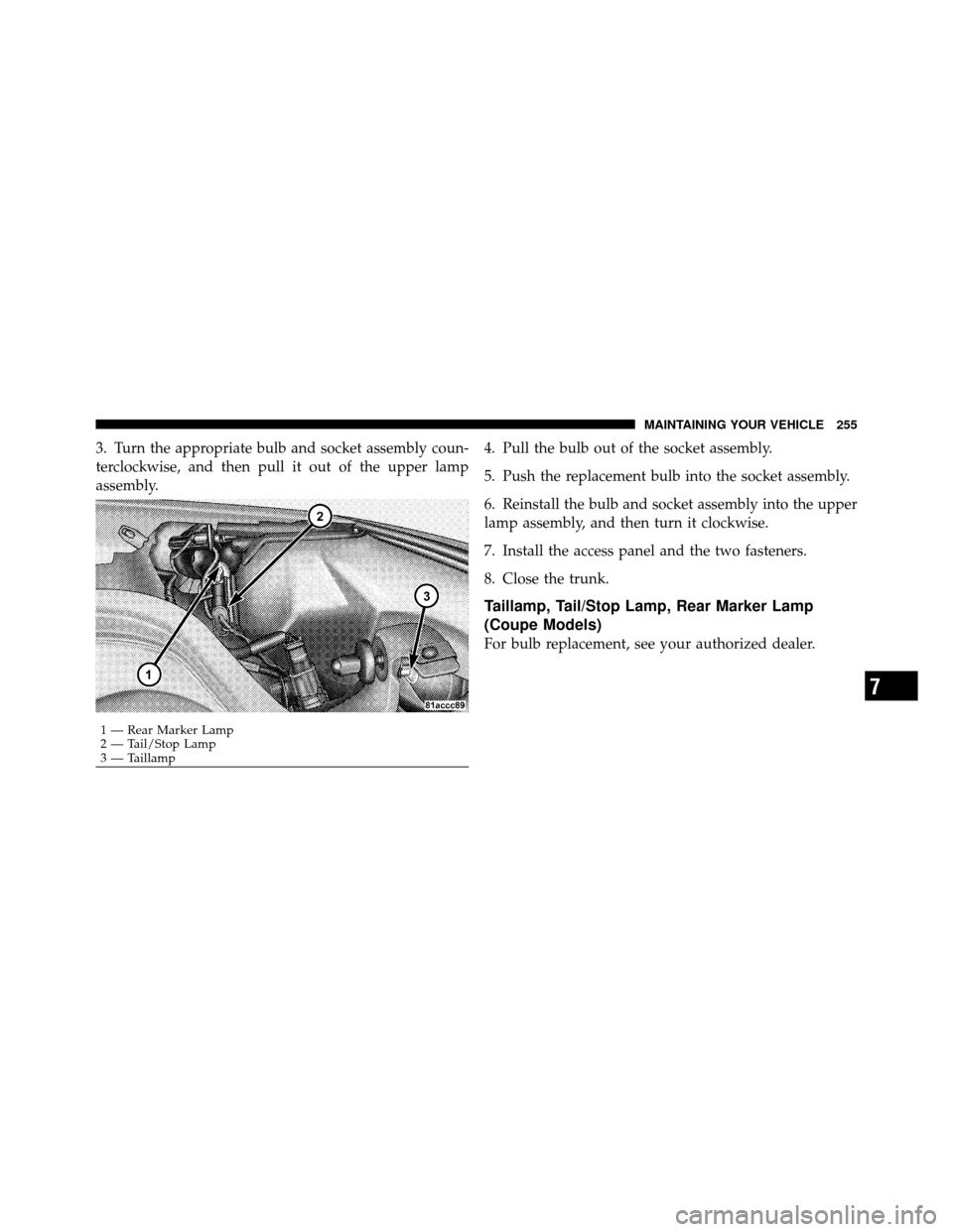
3. Turn the appropriate bulb and socket assembly coun-
terclockwise, and then pull it out of the upper lamp
assembly.4. Pull the bulb out of the socket assembly.
5. Push the replacement bulb into the socket assembly.
6. Reinstall the bulb and socket assembly into the upper
lamp assembly, and then turn it clockwise.
7. Install the access panel and the two fasteners.
8. Close the trunk.
Taillamp, Tail/Stop Lamp, Rear Marker Lamp
(Coupe Models)
For bulb replacement, see your authorized dealer.
1 — Rear Marker Lamp
2 — Tail/Stop Lamp
3 — Taillamp
7
MAINTAINING YOUR VEHICLE 255
Page 260 of 315
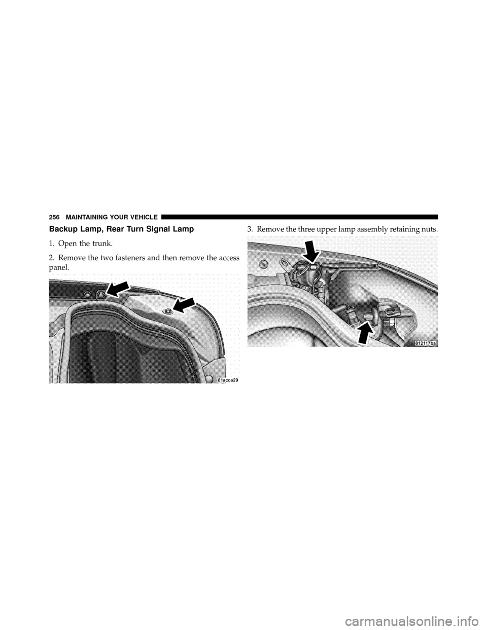
Backup Lamp, Rear Turn Signal Lamp
1. Open the trunk.
2. Remove the two fasteners and then remove the access
panel.3. Remove the three upper lamp assembly retaining nuts.
256 MAINTAINING YOUR VEHICLE