lock DODGE VIPER 2010 ZB II / 2.G Owner's Manual
[x] Cancel search | Manufacturer: DODGE, Model Year: 2010, Model line: VIPER, Model: DODGE VIPER 2010 ZB II / 2.GPages: 80, PDF Size: 8.08 MB
Page 25 of 80
Clock Setting
• Turn the ignition switch to the ON/RUN or ACC position.
• Using the point of a ballpoint pen or similar object, press either the H (HOUR) or M(MINUTE) button on the radio. The display will show the time.
• Press the “H” button to set hours or the “M” button to set minutes. The time setting
will increase each time you press a button.
Station Presets
• Press the SET button once and SET 1 will show in the display. Then select the button (1–5).
• A second station may be added to each pushbutton. Press the SET button twice and SET 2 will show in the display, then select button (1–5).
23
ELECTRONICS
Page 26 of 80
NON-TOUCH-SCREEN RADIO
Navigation Radio – RB1
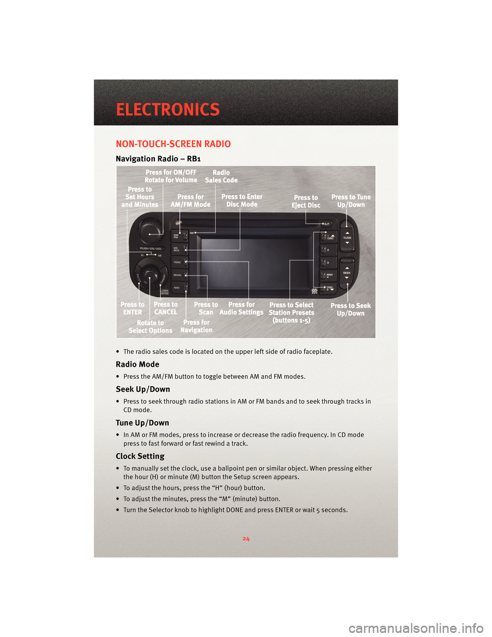
• The radio sales code is located on the upper left side of radio faceplate.
Radio Mode
• Press the AM/FM button to toggle between AM and FM modes.
Seek Up/Down
• Press to seek through radio stations in AM or FM bands and to seek through tracks inCD mode.
Tune Up/Down
• In AM or FM modes, press to increase or decrease the radio frequency. In CD modepress to fast forward or fast rewind a track.
Clock Setting
• To manually set the clock, use a ballpoint pen or similar object. When pressing eitherthe hour (H) or minute (M) button the Setup screen appears.
• To adjust the hours, press the “H” (hour) button.
• To adjust the minutes, press the “M” (minute) button.
• Turn the Selector knob to highlight DONE and press ENTER or wait 5 seconds.
ELECTRONICS
24
Page 27 of 80
Daylight Savings
• Use a ball point pen or similar object to press the "H" (hour) or "M" (Minute) button toaccess the clock setup screen.
• Press ENTER to select Clock Setup.
• Rotate the Selector knob to highlight Daylight Savings and press ENTER.
• Rotate the Selector knob to highlight St andard or Daylight Savings and press ENTER.
• Turn the Selector knob to highlight DONE and press ENTER or wait 5 seconds.
Changing Time Zone
• Use a ball point pen or similar object to press the "H" (hour) or "M" (Minute) button to access the clock setup screen.
• Press ENTER to select Clock Setup.
• Rotate the Selector knob to highlight Time Zone and press ENTER.
• Rotate the Selector knob to highlight the desired Time Zone and press ENTER.
• Turn the Selector knob to highlight DONE and press ENTER or wait 5 seconds.
Store Radio Presets
• Find the station to store by either pressing the seek up/down button, the tune up/down button, or by t ouching the SCAN button.
• Turn the Selector knob to highlight SET and press ENTER. SET 1 appears on the display.
• Then select button (1–5).
• You may add a second station to each pushb utton by repeating the above procedure
with this exception: After highlighting SET, press ENTER twice. SET 2 appears on the
display, then select button (1–5).
Navigation
Navigation Radio – RB1 Only
• Your navigation system receives GPS signals from up to 8 satellites to display the position and direction of your vehicle.
• Map and database information is supplied through a DVD-ROM and vehicle sensors enable the system to display the present vehicle position even in locations where GPS
may be blocked.
• The DVD-ROM disc must be inserted into the radio before accessing the Navigation mode.
NOTE: Many features of this radio are speed dependent. For your own safety, some of
the programmable options will be grayed out and unavailable while the vehicle is in
motion. Pull over at a safe location to complete your task.
New Destination
• Press the NAV button to access the NAV Main Menu.
• Using the Selector knob, highlight Destination to program a destination, press ENTER, then select one of the 8 ways to input a destination.
25
ELECTRONICS
Page 35 of 80
Wing Stanchions
• The wing stanchions are designed with adjustment capability but they are delivered
locked with tamper resistant fasteners.
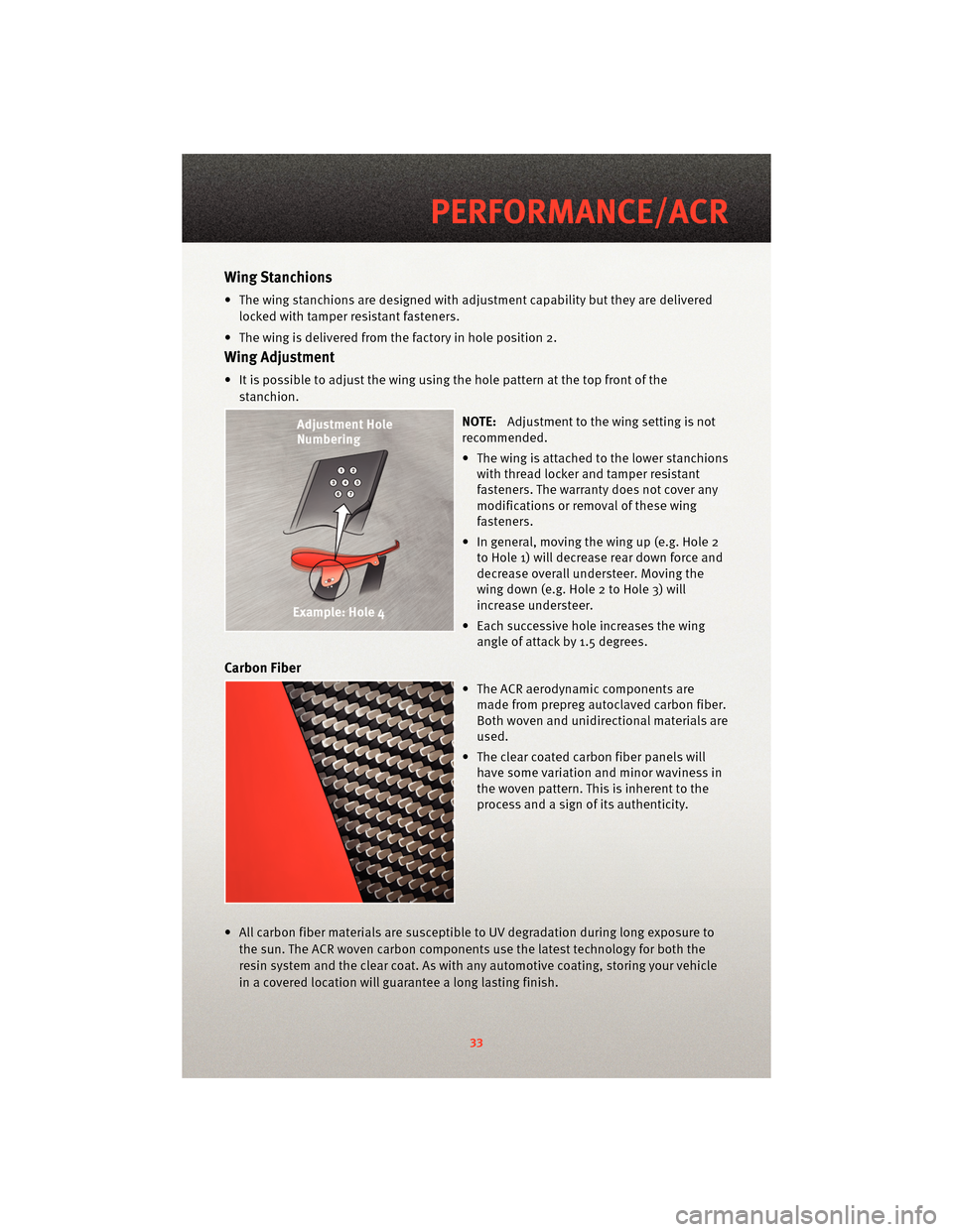
• The wing is delivered from the factory in hole position 2.
Wing Adjustment
• It is possible to adjust the wing using the hole pattern at the top front of the stanchion.
NOTE:Adjustment to the wing setting is not
recommended.
• The wing is attached to the lower stanchions with thread locker and tamper resistant
fasteners. The warranty does not cover any
modifications or removal of these wing
fasteners.
• In general, moving the wing up (e.g. Hole 2 to Hole 1) will decrease rear down force and
decrease overall understeer. Moving the
wing down (e.g. Hole 2 to Hole 3) will
increase understeer.
• Each successive h ole increases the wing
angle of attack by 1.5 degrees.
Carbon Fiber
• The ACR aerodynamic components are made from prepreg autoclaved carbon fiber.
Both woven and unidirectional materials are
used.
• The clear coated carbon fiber panels will have some variation and minor waviness in
the woven pattern. This is inherent to the
process and a sign of its authenticity.
• All carbon fiber materials are susceptible to UV degradation during long exposure to
the sun. The ACR woven carbon components use the latest technology for both the
resin system and the clear coat. As with any automotive coating, storing your vehicle
in a covered location will guarantee a long lasting finish.
33
PERFORMANCE/ACR
Page 41 of 80
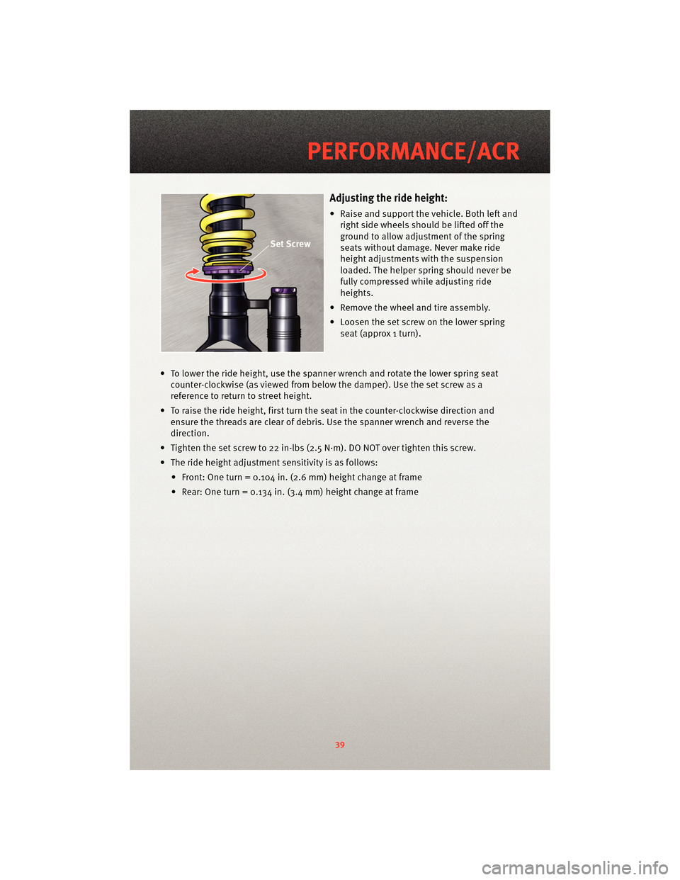
Adjusting the ride height:
• Raise and support the vehicle. Both left andright side wheels should be lifted off the
ground to allow adjustment of the spring
seats without damage. Never make ride
height adjustments with the suspension
loaded. The helper spring should never be
fully compressed while adjusting ride
heights.
• Remove the wheel and tire assembly.
• Loosen the set screw on the lower spring seat (approx 1 turn).
• To lower the ride height, use the spanner wrench and rotate the lower spring seat counter-clockwise (as viewed fr om below the damper). Use the set screw as a
reference to return to street height.
• To raise the ride height, first turn the seat in the counter-clockwise direction and ensure the threads are clear of debris. Use the spanner wrench and reverse the
direction.
• Tighten the set screw to 22 in-lbs (2.5 N·m). DO NOT over tighten this screw.
• The ride height adjustment sensitivity is as follows: • Front: One turn = 0.104 in. (2.6 mm) height change at frame
• Rear: One turn = 0.134 in. (3.4 mm) height change at frame
39
PERFORMANCE/ACR
Page 42 of 80
Compression Adjustment
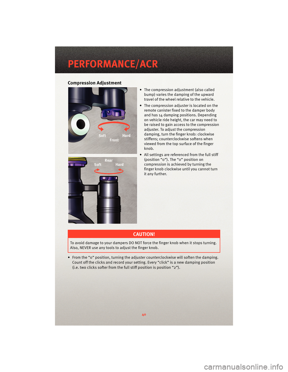
• The compression adjustment (also calledbump) varies the damping of the upward
travel of the wheel relative to the vehicle.
• The compression adjuster is located on the remote canister fixed to the damper body
and has 14 damping positions. Depending
on vehicle ride height, the car may need to
be raised to gain access to the compression
adjuster. To adjust the compression
damping, turn the finge r knob: clockwise
stiffens; counterclockwise softens when
viewed from the top surface of the finger
knob.
• All settings are referenced from the full stiff (position “0”). The “0” position on
compression is achieved by turning the
finger knob clockwise until you cannot turn
it any further.
CAUTION!
To avoid damage to your dampers DO NOT force the finger knob when it stops turning.
Also, NEVER use any tools to adjust the finger knob.
• From the “0” position, turning the adjuster cou nterclockwise will soften the damping.
Count off the clicks and record your setting. Every “click” is a new damping position
(i.e. two clicks softer from the full stiff position is position “2”).
PERFORMANCE/ACR
40
Page 43 of 80
Rebound Adjustment
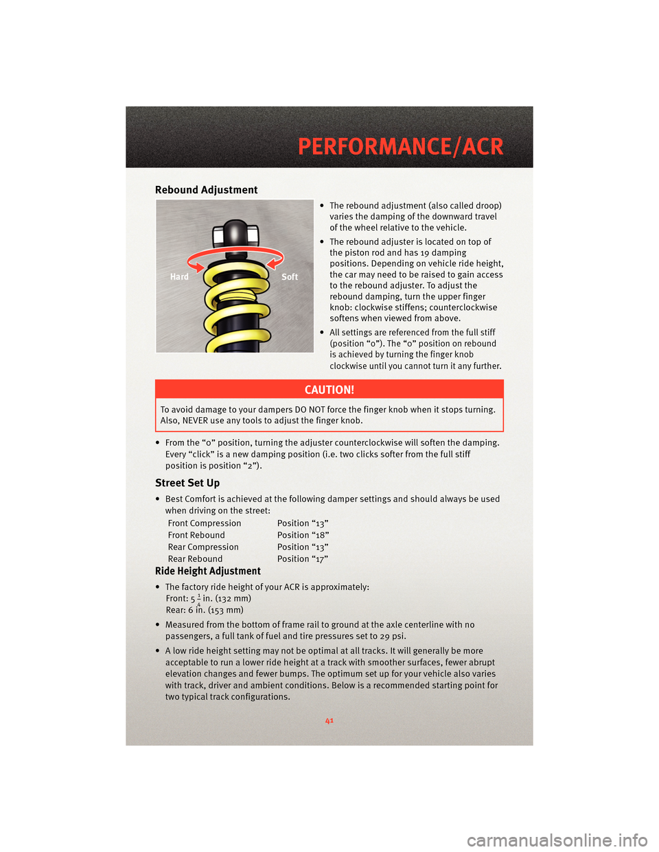
• The rebound adjustment (also called droop)varies the damping of the downward travel
of the wheel relative to the vehicle.
• The rebound adjuster is located on top of the piston rod and has 19 damping
positions. Depending on vehicle ride height,
the car may need to be raised to gain access
to the rebound adjuster. To adjust the
rebound damping, turn the upper finger
knob: clockwise stiffens; counterclockwise
softens when viewed from above.
•
All settings are referenced from the full stiff
(position “0”). The “0” position on rebound
is achieved by turning the finger knob
clockwise until you cannot turn it any further.
CAUTION!
To avoid damage to your dampers DO NOT force the finger knob when it stops turning.
Also, NEVER use any tools to adjust the finger knob.
• From the “0” position, turning the adjuster cou nterclockwise will soften the damping.
Every “click” is a new damping position (i.e. two clicks softer from the full stiff
position is position “2”).
Street Set Up
• Best Comfort is achieved at the following damper settings and should always be used when driving on the street:
Front Compression Position “13”
Front Rebound Position “18”
Rear Compression Position “13”
Rear Rebound Position “17”
Ride Height Adjustment
• The factory ride height of your ACR is approximately: Front: 514in. (132 mm)
Rear: 6 in. (153 mm)
• Measured from the bottom of frame rail to ground at the axle centerline with no passengers, a full tank of fuel and tire pressures set to 29 psi.
• A low ride height setting may not be optimal at all tracks. It will generally be more acceptable to run a lower ride height at a track with smoother surfaces, fewer abrupt
elevation changes and fewer bumps. The optimum set up for your vehicle also varies
with track, driver and ambient conditions. Below is a recommended starting point for
two typical track configurations.
41
PERFORMANCE/ACR
Page 47 of 80
LIMITED WARRANTY
• The ACR offers many race-ready components that are designed for uncompromising
performance. Because of this, some of the ACR components have unique warranty
limitations.
Racing Not Covered
• The warranty does not cover the cost of repairing damage or conditions caused by racing, nor does it cover the repair for any defects that are found as the result of
participating in a racing event. The term racing includes but is not exclusive to: wheel
to wheel competition, timed competitive events, autocross or other off-road track
events.
Splitter
• The splitter is not covered for wear on the rub strips or damage due to contact with parking blocks, speed bumps, curbs, s loped tarmac, etc. The warranty is not valid if
adjustments or modifications are made to the splitter.
Wing
• The warranty does not cover any adjustments or modifications made to the wing or if the original fasteners or positions have been changed.
Tires
• 12 months / 12,000 miles - Excessive tire wear due to track events, autocross,competition, etc. are not covered.
Brake Pads/Rotors
• 12 months / 12,000 miles - Excessive brake pad and rotor wear due to track events,autocross, competition, etc. are not covered. No warranty for noise complaints.
Adjustable Coil-over Shocks
• The factory warranty is 12 months / 12,000 miles. KW Suspensions has an extendedsupplier warranty up to 36 months or 36,000 miles. The warranty is not valid if
modifications or improper adjustments are made to the factory settings.
KW automotive North America Inc.
1075 North Avenue
Sanger, CA 93657
Toll Free: 1-888-713-5566
Email: [email protected]
http://www.kw-suspension.com/en/
45
PERFORMANCE/ACR
Page 50 of 80
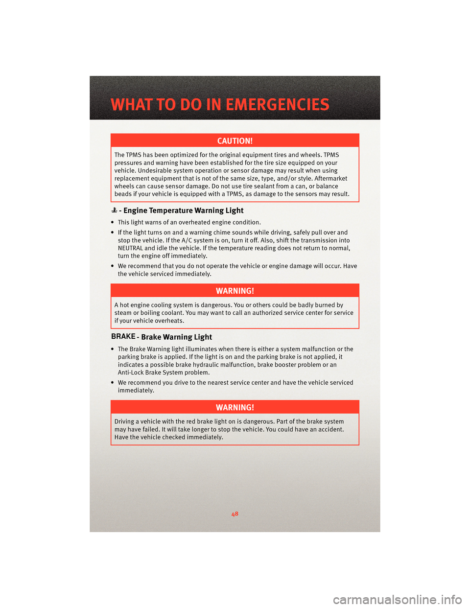
CAUTION!
The TPMS has been optimized for the original equipment tires and wheels. TPMS
pressures and warning have been established for the tire size equipped on your
vehicle. Undesirable system operation or sensor damage may result when using
replacement equipment that is not of the same size, type, and/or style. Aftermarket
wheels can cause sensor damage. Do not use tire sealant from a can, or balance
beads if your vehicle is equipped with a TPMS, as damage to the sensors may result.
- Engine Temperature Warning Light
• This light warns of an overheated engine condition.
• If the light turns on and a warning chime sounds while driving, safely pull over andstop the vehicle. If the A/C system is on, t urn it off. Also, shiftthe transmission into
NEUTRAL and idle the vehicle. If the temperat ure reading does not return to normal,
turn the engine off immediately.
• We recommend that you do not operate the vehicle or engine damage will occur. Have the vehicle serviced immediately.
WARNING!
A hot engine cooling system is dangero us. You or others could be badly burned by
steam or boiling coolant. You may want to call an authorized service center for service
if your vehicle overheats.
- Brake Warning Light
• The Brake Warning light illuminates when there is either a system malfunction or the parking brake is applied. If the light is on and the parking brake is not applied, it
indicates a possible brake hydraulic malfunction, brake booster problem or an
Anti-Lock Brake System problem.
• We recommend you drive to the nearest service center and have the vehicle serviced immediately.
WARNING!
Driving a vehicle with the red brake light on is dangerous. Part of the brake system
may have failed. It will take longer to stop the vehicle. You could have an accident.
Have the vehicle checked immediately.
WHAT TO DO IN EMERGENCIES
48
Page 51 of 80
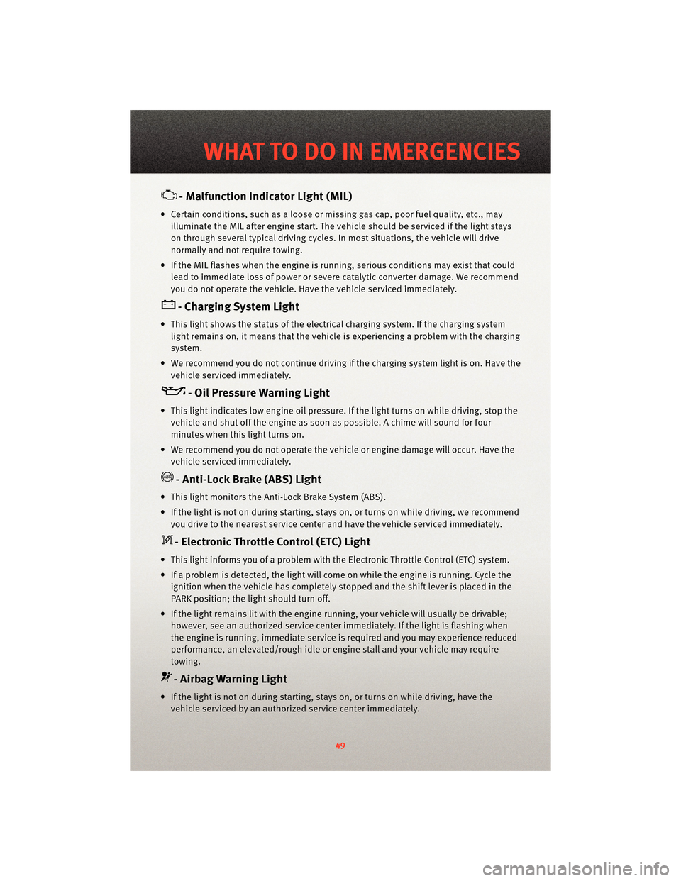
- Malfunction Indicator Light (MIL)
• Certain conditions, such as a loose or missing gas cap,poor fuel quality, etc., may
illuminate the MIL after engine start. The vehicle should be serviced if the light stays
on through several typical driving cycles. In most situations, the vehicle will drive
normally and not require towing.
• If the MIL flashes when the engine is running, serious conditions may exist that could lead to immediate loss of power or severe catalytic converter damage. We recommend
you do not operate the vehicle. Hav e the vehicle serviced immediately.
- Charging System Light
• This light shows the status of the electrical ch arging system. If the charging system
light remains on, it means that the vehicle is experiencing a problem with the charging
system.
• We recommend you do not continue driving if the charging system light is on. Have the vehicle serviced immediately.
- Oil Pressure Warning Light
• This light indicates low engine oil pressure. If the light turns on while driving, stop thevehicle and shut off the engine as soon as possible. A chime will sound for four
minutes when this light turns on.
• We recommend you do not operate the vehicle or engine damage will occur. Have the vehicle serviced immediately.
- Anti-Lock Brake (ABS) Light
• This light monitors the Anti-Lock Brake System (ABS).
• If the light is not on during starting, stays on, or turns on while driving, we recommendyou drive to the nearest service center and have the vehicle serviced immediately.
- Electronic Throttle Control (ETC) Light
• This light informs you of a problem with the Electronic Throttle Control (ETC) system.
• If a problem is detected, the light will come on while the engine is running. Cycle theignition when the vehicle has completely stopped and the shift lever is placed in the
PARK position; the light should turn off.
• If the light remains lit with the engine running, your vehicle will usually be drivable; however, see an authorized service center immediately. If the light is flashing when
the engine is running, immediate service is required and you may experience reduced
performance, an elevated/rough idle or en gine stall and your vehicle may require
towing.
- Airbag Warning Light
• If the light is not on during starting, stays on, or turns on while driving, have the vehicle serviced by an authorized service center immediately.
49
WHAT TO DO IN EMERGENCIES