tire pressure DODGE VIPER 2010 ZB II / 2.G User Guide
[x] Cancel search | Manufacturer: DODGE, Model Year: 2010, Model line: VIPER, Model: DODGE VIPER 2010 ZB II / 2.GPages: 80, PDF Size: 8.08 MB
Page 3 of 80
INTRODUCTION/WELCOME
WELCOME FROM CHRYSLER GROUP
LLC ..................... 2
CONTROLS AT A GLANCE
DRIVER COCKPIT.............. 4
INSTRUMENT CLUSTER ..........6
GETTING STARTED
KEYFOB...................8
MANUAL DOOR LOCK........... 9
THEFT ALARM ................ 9
ENGINE START BUTTON ..........10
SEATBELT .................11
CHILD RESTRAINTS .............11
FRONTSEATS................13
TILT STEERING COLUMN ..........14
ADJUSTABLEPEDALS ...........15
PROGRAMMABLEFEATURES .......16
OPERATING YOUR VEHICLE
TURN SIGNAL/LIGHTS LEVER .......17
WIPER/WASHER LEVER ..........18
MANUAL TRANSMISS ION 1 TO 4 SKIP
SHIFT ....................18
MANUAL CLIMATE CONTROLS .......19
CONVERTIBLE TOP OPERATION ..... 20
WIND BUFFETING ..............21
ELECTRONICS
NON-TOUCH-SCREENRADIO....... 22
NON-TOUCH-SCREENRADIO....... 24
POWER OUTLET..............27
PERFORMANCE/ACR
OVERVIEW ................ 28
AERODYNAMICS............. 29
TWO PIECE BRAKE ROTORS ........34
PILOTSPORTCUPTIRES......... 36
ADJUSTABLE DAMPERS ..........37
HARDCOREPACKAGE ...........43 TUNINGRECORD ..............44
LIMITED WARRANTY
............45
ACKNOWLEDGEMENT .......... 46
WHAT TO DO IN EMERGENCIES
24-HOUR TOWINGASSISTANCE -
U.S. ONLY .................47
INSTRUMENT CLUSTER WARNING
LIGHTS ...................47
IF YOUR ENGINE OVERHEATS .......50
TIREFIT TIRE REPAIR ............51
JUMP-STARTING ..............54
TOWINGADISABLEDVEHICLE.......56
FREEING A STUCK VEHICLE ........57
EVENT DATA RECORDER (EDR) ......58
MAINTAINING YOUR VEHICLE
OPENING THE HOOD............59
ENGINE COMPARTMENT ......... 60
FLUIDS AND CAPACITIES ..........61
MAINTENANCE CHART B ......... 62
FUSES................... 64
TIREPRESSURES..............65
WHEEL AND WHEEL TRIM CARE ..... 66
EXTERIOR BULBS ............. 66
VEHICLESTORAGE .............67
CONSUMER ASSISTANCE
CHRYSLER GROUP LLC CUSTOMER
CENTER.................. 69
CHRYSLER CANADA INC. CUSTOMER
CENTER.................. 69
ASSISTANCE F OR THE HEARING
IMPAIRED................. 69
PUBLICATIONS ORDERING ........ 69
REPORTING SAFETY DEFECTS IN
THE 50 UNITED STATES AND
WASHINGTON, D.C. ............70
TIRE WARRANTY ..............70
MOPAR ACCESSORIES
MOPAR®ACCESSORIES..........73
TABLE OF CONTENTS
Page 8 of 80
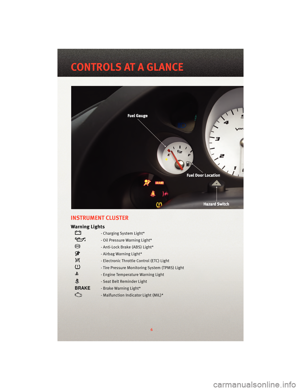
INSTRUMENT CLUSTER
Warning Lights
- Charging System Light*
- Oil Pressure Warning Light*
- Anti-Lock Brake (ABS) Light*
- Airbag Warning Light*
- Electronic Throttle Control (ETC) Light
- Tire Pressure Monitoring System (TPMS) Light
- Engine Temperature Warning Light
- Seat Belt Reminder Light
- Brake Warning Light*
- Malfunction Indicator Light (MIL)*
6
CONTROLS AT A GLANCE
Page 9 of 80
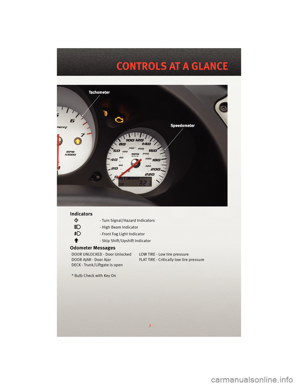
Indicators
- Turn Signal/Hazard Indicators
- High Beam Indicator
- Front Fog Light Indicator
- Skip Shift/Upshift Indicator
Odometer Messages
DOOR UNLOCKED - Door Unlocked LOW TIRE - Low tire pressure
DOOR AJAR - Door Ajar FLAT TIRE - Critically low tire pressure
DECK - Trunk/Liftgate is open
* Bulb Check with Key On
7
CONTROLS AT A GLANCE
Page 39 of 80
WARNING!
The Pilot Sport Cup tires were NOT intended to be driven on snow or ice. The Pilot
Sport Cup is a summer season tire and has diminished capability on cold road
surfaces (below 50°F). DO NOT OPERATE THE VEHICLE DURING THESE CONDITIONS.
Snow, ice and cold road surfaces can cause a loss of control or accident.
ADJUSTABLE DAMPERS
• The Viper ACR suspension includes a set of adjustable coil-over racing dampers built
by KW Suspensions. These dampers hav e been tuned by SRT handling engineers to
provide the maximum handling performance without sacrificing reasonable road
manners.
• The two-way adjustable dampers inc lude adjustments for compression (bump) and
rebound damping.
NOTE: Keep your damper settings at the street positions when operating your vehicle on
the street.
WARNING!
Only experienced track drivers should ma ke adjustments to the suspension settings.
Improper suspension adjustment can disrupt the balance of the vehicle and lead to a
loss of control or accident.
CAUTION!
Do not make any adjustments or modifications to the nitrogen pressure of the damper
canisters. This will void the warranty.
• The ACR suspension was designed and tuned with an uncompromising focus on handling. The ride response to road conditions m ay be harsher than expected from a
typical sports car.
37
PERFORMANCE/ACR
Page 43 of 80
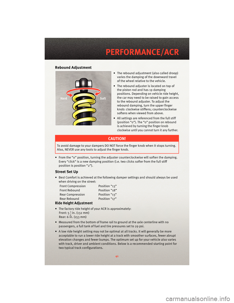
Rebound Adjustment
• The rebound adjustment (also called droop)varies the damping of the downward travel
of the wheel relative to the vehicle.
• The rebound adjuster is located on top of the piston rod and has 19 damping
positions. Depending on vehicle ride height,
the car may need to be raised to gain access
to the rebound adjuster. To adjust the
rebound damping, turn the upper finger
knob: clockwise stiffens; counterclockwise
softens when viewed from above.
•
All settings are referenced from the full stiff
(position “0”). The “0” position on rebound
is achieved by turning the finger knob
clockwise until you cannot turn it any further.
CAUTION!
To avoid damage to your dampers DO NOT force the finger knob when it stops turning.
Also, NEVER use any tools to adjust the finger knob.
• From the “0” position, turning the adjuster cou nterclockwise will soften the damping.
Every “click” is a new damping position (i.e. two clicks softer from the full stiff
position is position “2”).
Street Set Up
• Best Comfort is achieved at the following damper settings and should always be used when driving on the street:
Front Compression Position “13”
Front Rebound Position “18”
Rear Compression Position “13”
Rear Rebound Position “17”
Ride Height Adjustment
• The factory ride height of your ACR is approximately: Front: 514in. (132 mm)
Rear: 6 in. (153 mm)
• Measured from the bottom of frame rail to ground at the axle centerline with no passengers, a full tank of fuel and tire pressures set to 29 psi.
• A low ride height setting may not be optimal at all tracks. It will generally be more acceptable to run a lower ride height at a track with smoother surfaces, fewer abrupt
elevation changes and fewer bumps. The optimum set up for your vehicle also varies
with track, driver and ambient conditions. Below is a recommended starting point for
two typical track configurations.
41
PERFORMANCE/ACR
Page 44 of 80
Smooth track set up:
Front: 4 in. (102 mm)
Rear: 5 3/8 in. (136 mm)
Rough track set up:
Front: 4.375 in. (111 mm)
Rear: 5 1/2 in. (140 mm)
• The rake of the car (or front to rear ride height difference) may also be changed with your ACR suspension. Changing the rake may be beneficial at some tracks. Use
caution when changing the rake angle.
CAUTION!
Depending on your set up, driving styl e, and track condition, some tire to wheel liner
contact may occur. To avoid excessive wheel liner wear, adjust your ride height
accordingly.
Notes on Tuning
Damper Adjustment
• Adjusting from the street settings should be done only at track events. A
recommended starting position for the tracks is:
Front Compression Position “6”
Front Rebound Position “6”
Rear Compression Position “5”
Rear Rebound Position “5”
• Always start from a known position (full stiff).
• Adjust in small increments (1-2 clicks).
• Record your adjustment settings at all four wheels.
• Continually monitor and record your tire pressures.
• Remember that suspension damping, ride heights, rake angle and aerodynamic
balance all work as a system. As you make changes to one end of the vehicle, it will
affect the balance of the car.
Maintenance and Inspection
• Regularly inspect the splitter rub strips and out board knock-in nut. Regularly inspect
all attachments of the aerodynamic components (see Aerodynamics section).
• Track use will greatly increase wear rates and service intervals on your Viper ACR. Repeated track use requires more frequent fluid changes.
NOTE: Although your vehicle is shipped with 0W40, it is recommended to use Mobil-1
15W50 synthetic motor oil at the track.
• Always run a cool down lap at the end of a track outing. For track outings lasting longer than 25 minutes, an external rear axle cooler is recommended.
PERFORMANCE/ACR
42
Page 49 of 80
24-HOUR TOWING ASSISTANCE - U.S. ONLY
• Dial toll-free 1-800-521-2779 or 1-800-363-4869 for Canadian residents.
• Provide your name, vehicle identification number and license plate number.
• Provide your location, including telephone number, from which you are calling.
• Briefly describe the nature of the problem and answer a few simple questions.
• You will be given the name of the service provider and an estimated time of arrival. Ifyou feel you are in an “unsafe situation”, please let us know. With your consent, we
will contact local police or safety authorities.
INSTRUMENT CLUSTER WARNING LIGHTS
- Tire Pressure Monitoring System (TPMS) Light
• Each tire, including the spare (if provided), should be checked monthly, when coldand inflated to the inflation pressure recommended by the vehicle manufacturer on
the vehicle placard or tire inflation pressure label. (If your vehicle has tires of a
different size than the size indicated on the v ehicle placard or tire inflation pressure
label, you should determine the proper tire inflation pressure for those tires.)
• As an added safety feature, your vehicle has been equipped with a Tire Pressure Monitoring System (TPMS) that illuminates a low tire pressure telltale when one or
more of your tires is significantly under-inflat ed. Accordingly, when the low tire
pressure telltale illuminates, you should stop and check your tires as soon as
possible, and inflate them to the proper pressure. Driving on a significantly
under-inflated tire causes the tire to overheat and can lead to tire failure.
Under-inflation also reduces fuel efficiency and tire tread life, and may affect the
vehicle’s handling and stopping ability.
• Please note that the TPMS is not a subs titute for proper tire maintenance, and it is the
driver’s responsibility to maintain correct tire pressure, even if under-inflation has not
reached the level to trigger illumination of the TPMS low tire pressure telltale.
• Your vehicle has also been equipped with a TPMS malfunction indicator to indicate
when the system is not operating properly. The TPMS malfunction indicator is
combined with the low tire pressure telltale. When the system detects a malfunction,
the telltale will flash for approximately one minute and then remain continuously
illuminated. This sequence will continue upon subsequent vehicle start-ups as long as
the malfunction exists.
• When the malfunction indicator is illuminated, the system may not be able to detect or signal low tire pressure as intended. TPMS malfunctions may occur for a variety of
reasons, including the installation of replacement or alternate tires or wheels on the
vehicle that prevent the TPMS from functioning properly. Always check the TPMS
malfunction telltale after replacing one or more tires or wheels on your vehicle, to
ensure that the replacement or alternate tires and wheels allow the TPMS to continue
to function properly.
47
WHAT TO DO IN EMERGENCIES
Page 50 of 80
CAUTION!
The TPMS has been optimized for the original equipment tires and wheels. TPMS
pressures and warning have been established for the tire size equipped on your
vehicle. Undesirable system operation or sensor damage may result when using
replacement equipment that is not of the same size, type, and/or style. Aftermarket
wheels can cause sensor damage. Do not use tire sealant from a can, or balance
beads if your vehicle is equipped with a TPMS, as damage to the sensors may result.
- Engine Temperature Warning Light
• This light warns of an overheated engine condition.
• If the light turns on and a warning chime sounds while driving, safely pull over andstop the vehicle. If the A/C system is on, t urn it off. Also, shiftthe transmission into
NEUTRAL and idle the vehicle. If the temperat ure reading does not return to normal,
turn the engine off immediately.
• We recommend that you do not operate the vehicle or engine damage will occur. Have the vehicle serviced immediately.
WARNING!
A hot engine cooling system is dangero us. You or others could be badly burned by
steam or boiling coolant. You may want to call an authorized service center for service
if your vehicle overheats.
- Brake Warning Light
• The Brake Warning light illuminates when there is either a system malfunction or the parking brake is applied. If the light is on and the parking brake is not applied, it
indicates a possible brake hydraulic malfunction, brake booster problem or an
Anti-Lock Brake System problem.
• We recommend you drive to the nearest service center and have the vehicle serviced immediately.
WARNING!
Driving a vehicle with the red brake light on is dangerous. Part of the brake system
may have failed. It will take longer to stop the vehicle. You could have an accident.
Have the vehicle checked immediately.
WHAT TO DO IN EMERGENCIES
48
Page 54 of 80
TIREFIT Instructions
• TIREFIT will temporarily seal small punctures up to14in.(6 mm) in the tire tread allowing
you to drive your vehicle up to 100 mi (160 km) with a maximum speed of 55 mph
(90 km/hr). TIREFIT can be used in outside temperatures down to approximately -4°F
(-20°C).
NOTE: Do not remove foreign objects (e.g., screws or nails) from the tire.
• Verify that the valve stem is close to the ground.
• Put on the gloves from the TIREFIT Kit Accessory Storage Compartment.
• Turn the Mode Select knob to the Sealant Mode position
.
• Remove the Yellow Cap from the fitting at the end of the Clear Sealant Hose.
• Remove the valve stem cap and screw the fitting at the end of the Clear Sealant Hose onto the valve stem.
• Insert the Power Plug into the vehicle’s 12-volt power outlet.
• Start the engine and then press the Power button
. The sealant (white fluid) will
flow from the Sealant Bottle through the Clear Sealant Hose and into the tire.
NOTE:
• Sealant may leak out through the puncture in the tire.
• If the sealant (white fluid) does not flow withi n0–10secondsthrough the Clear
Sealant Hose: • Press the Power button
to turn OFF the TIREFIT kit.
• Disconnect the Clear Sealant Hose and make sure the valve stem is free of debris.
• Repeat previous steps to verify sealant will flow, making sure the Mode Select knob is in Sealant Mode
.
• Continue to operate the pump until seal ant is no longer flowing through the hose
(typically takes 30 - 70 seconds). As the sealant flows through the Clear Sealant Hose,
the pressure gauge can read as high as 70 psi. The pressure gauge will decrease
quickly from approximately 70 psi to the actual tire pressure when the sealant bottle is
empty.
• The pump will start to inject air into the tire immediately after the sealant bottle is
empty. Continue to operate the pump and inflate the tire to the pressure indicated on
the Tire and Loading Information label on the driver's side door opening. Check the
tire pressure by looking at the pressure gauge.
NOTE: If the tire does not inflate to at least 26 psi pressure within 15 minutes, the tire is
too badly damaged. Do not attempt to drive the vehicle further. Call for assistance.
• If the tire inflates to the recommended pressure or is at least 26 psi pressure within 15 minutes, press the Power button
to turn off the TIREFIT kit.
• Remove the Speed Limit sticker from the top of the Sealant Bottle and place the sticker on the steering wheel.
• Immediately disconnect the Clear Sealant Ho se from the valve stem, reinstall the
Yellow Cap on the fitting at the end of the hose, and place the TIREFIT kit in the vehicle
storage location. Quickly proceed to the next step.
WHAT TO DO IN EMERGENCIES
52
Page 55 of 80
CAUTION!
• The metal end fitting from the Power Plug and Cable may get hot after use andshould be handled carefully.
• Failure to reinstall the Yellow Cap on the fitting at the end of the Clear Sealant Hose can result in sealant contacting your skin, clothing, and the vehicle’s interior. It can
also result in sealant contacting internal TIREFIT kit components which may cause
permanent damage to the kit.
• Immediately after injecting sealant and infl ating the tire, drive the vehicle 5 mi (8 km)
or 10 minutes to ensure distribution of the TIREFIT Sealant within the tire. Do not
exceed 55 mph (88 km/h).
• Pull over and repeat Preparations for Jacking or Tire Repair.
• Turn the Mode Select knob to the Air Mode position
.
• Connect the Black Air Pump Hose to the valve stem.
• Check the pressure in the tire by reading the Pressure Gauge.
NOTE: If tire pressure is less than 19 psi, the tire is too badly damaged. Do not attempt
to drive the vehicle fur ther. Call forassistance.
• If the tire pressure is 19 psi or higher, press the Power button
and inflate the tire
to the pressure indicated on the Tire and Loading Information label on the driver's
side door opening.
• Disconnect the TIREFIT kit from the valve stem and then reinstall the valve stem cap.
• Place the TIREFIT kit in its proper storage area in the vehicle.
• Have the tire inspected and repaired or replaced at the earliest opportunity at an authorized service center.
NOTE: When having the tire serviced, advise the authorized dealer or service center
that the tire has been sealed using the TIREFIT service kit.
• Refer to the Owner's Manual on the DVD for Sealant Bottle and Hose Replacement.
WARNING!
Do not use TIREFIT or drive the vehicle under the following circumstances:
• If the cut or puncture in the tire tread is approximately 0.24 in (6 mm) or larger.
• If the tire has any sidewall damage.
• If the tire has any damage from driv ing with extremely low tire pressure.
• If the tire has any damage from driving on a flat tire.
• If the wheel has any damage.
• If you are unsure of the condition of the tire or the wheel.
53
WHAT TO DO IN EMERGENCIES