light DODGE VIPER 2013 VX / 3.G Owner's Manual
[x] Cancel search | Manufacturer: DODGE, Model Year: 2013, Model line: VIPER, Model: DODGE VIPER 2013 VX / 3.GPages: 100, PDF Size: 3.1 MB
Page 63 of 100
UNIVERSAL GARAGE DOOR OPENER (HomeLink®)
•HomeLink®replaces up to three hand-held transmitters that operate devices such as
garage door openers, motorized gates, lighting or home security systems. The HomeLink®
unit is powered by your vehicles 12 Volt battery.
• The HomeLink®buttons that are located in the overhead console or sunvisor designate
the three different HomeLink®channels.
• The HomeLink
®indicator is located above the center button.
Before You Begin Programming
HomeLink®
• Be sure that your vehicle is parked out- side of the garage before you begin pro-
gramming.
•
For more efficient programming and accu-
rate transmission of the radio-frequency
signal it is recommended that a new bat-
tery be placed in the hand-held transmit-
ter of the device that is being programmed
to the HomeLink
®system.
• Erase all channels before you begin programming. To erase the channels, place the
ignition switch into the ON/RUN position, then press and hold the two outside
HomeLink
®buttons (I and III) for up 20 seconds or until the red indicator flashes.
NOTE:
• Erasing all channels should only be performed when programming HomeLink
®for the
first time. Do not erase channels when programming additional buttons.
• If you have any problems, or require assistance, please call toll-free 1–800–355–3515 or, on the Internet at www.HomeLink.com for information or assistance.
Programming A Rolling Code
• For programming Garage Door Openers that were manufactured after 1995. TheseGarage Door Openers can be identified by the “LEARN” or “TRAIN” button located
where the hanging antenna is attached to the Garage Door Opener. It is NOT the button
that is normally used to open and close the door. The name and color of the button may
vary by manufacturer.
• Place the ignition switch into the ON/RUN position.
• Place the hand-held transmitter 1 to 3 in (3 to 8 cm) away from the HomeLink
®button
you wish to program while keeping the HomeLink®indicator light in view.
• Simultaneously press and hold both the HomeLink
®button you want to program and
the hand-held transmitter button.
ELECTRONICS
61
Page 64 of 100
• Continue to hold both buttons and observe the indicator light. The HomeLink®
indicator will flash slowly and then rapidly after HomeLink®has received the frequency
signal from the hand-held transmitter. Release both buttons after the indicator light
changes from slow to rapid.
• At the garage door opener motor (in the garage), locate the “LEARN” or “TRAINING” button. This can usually be found where the hanging antenna wire is attached to the
garage door opener motor. Firmly press and release the “LEARN” or “TRAINING”
button.
NOTE:
You have 30 seconds in which to initiate the next step after the LEARN button has been
pressed.
• Return to the vehicle and press the programmed HomeLink
®button twice (holding the
button for two seconds each time). If the device is plugged in and activates, program-
ming is complete.
NOTE:
If the device does not activate, press the button a third time (for two seconds) to complete
the training.
• To program the remaining two HomeLink
®buttons, repeat each step for each remain-
ing button. DO NOT erase the channels.
Programming A Non-Rolling Code
• For programming Garage Door Openers manufactured before 1995.
• Turn the ignition switch to the ON/RUN position.
• Place the hand-held transmitter 1 to 3 in (3 to 8 cm) away from the HomeLink
®button
you wish to program while keeping the HomeLink®indicator light in view.
• Simultaneously press and hold both the HomeLink
®button you want to program and
the hand-held transmitter button.
• Continue to hold both buttons and observe the indicator light. The HomeLink
®
indicator will flash slowly and then rapidly after HomeLink®has received the frequency
signal from the hand-held transmitter. Release both buttons after the indicator light
changes from slow to rapid.
• Press and hold the programmed HomeLink
®button and observe the indicator light.
NOTE: • If the indicator light stays on constantly, programming is complete and the garagedoor (or device) should activate when the HomeLink
®button is pressed.
• To program the two remaining HomeLink
®buttons, repeat each step for each
remaining button. DO NOT erase the channels.
ELECTRONICS
62
Page 65 of 100
Using HomeLink®
• To operate, press and release the programmed HomeLink®button. Activation will now
occur for the programmed device (i.e., garage door opener, gate operator, security
system, entry door lock, home/office lighting, etc.,). The hand-held transmitter of the
device may also be used at any time.
WARNING!
• Your motorized door or gate will open and close while you are programming the
universal transceiver. Do not program the transceiver if people or pets are in the
path of the door or gate.
• Do not run your vehicle in a closed garage or confined area while programming the
transceiver. Exhaust gas from your vehicle contains Carbon Monoxide (CO) which is
odorless and colorless. Carbon Monoxide is poisonous when inhaled and can cause
you and others to be severely injured or killed.
POWER OUTLETS
• The auxiliary 12 Volt (13 Amp) power outlets can provide power for in-vehicleaccessories designed for use with the standard “cigar lighter” plug. The 12 Volt power
outlets have a cap attached to the outlet indicating “12V DC”, together with either a key
symbol or a battery symbol.
• The auxiliary power outlets can be found in the following locations: • To the right of the shifter on the console
• Inside the upper lid of the center stor-
age compartment — if equipped.
• Rear area of the center console.
NOTE:
• Do not exceed the maximum power of 160 Watts (13 Amps) at 12 Volts. If the
160 Watt (13 Amp) power rating is ex-
ceeded, the fuse protecting the system
will need to be replaced.
• Power outlets are designed for accessory plugs only. Do not insert any other object
in the power outlet as this will damage
the outlet and blow the fuse. Improper
use of the power outlet can cause dam-
age not covered by your new vehicle
warranty.
ELECTRONICS
63
Page 68 of 100
ELECTRONIC CONTROL DAMPING SYSTEM
• This vehicle may be equipped with an electronic controlled dampening system. Thissystem reduces body roll and pitch in many driving situations including cornering,
acceleration and braking.
• This system allows for a street suspension damping setting or a firmer race suspension damping setting. There are two modes of operation:
STREET MODE
• This mode will give a sporty, but comfort-able ride. Within this mode, the suspen-
sion will adapt to the vehicle inputs,
including vehicle speed, braking and
acceleration.
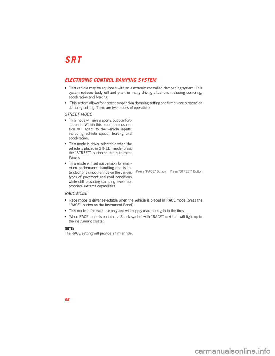
• This mode is driver selectable when the vehicle is placed in STREET mode (press
the “STREET” button on the Instrument
Panel).
• This mode will set suspension for maxi- mum performance handling and is in-
tended for a smoother ride on the various
types of pavement and road conditions
while still providing damping levels ap-
propriate extreme capabilities.
RACE MODE
• Race mode is driver selectable when the vehicle is placed in RACE mode (press the“RACE” button on the Instrument Panel).
• This mode is for track use only and will supply maximum grip to the tires.
• When RACE mode is enabled, a Shock symbol with “RACE” next to it will light up in the instrument cluster.
NOTE:
The RACE setting will provide a firmer ride.
SRT
66
Page 70 of 100
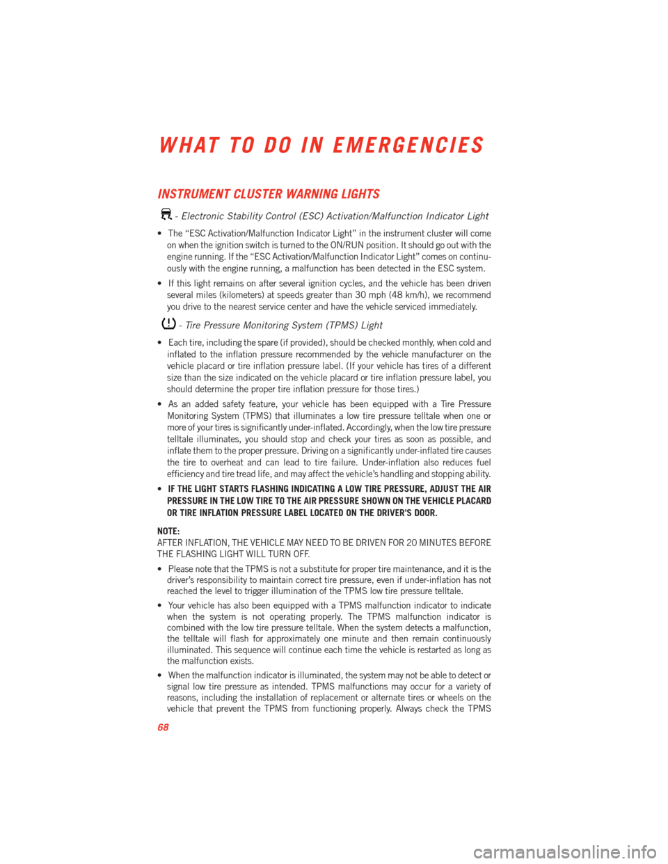
INSTRUMENT CLUSTER WARNING LIGHTS
- Electronic Stability Control (ESC) Activation/Malfunction Indicator Light
• The “ESC Activation/Malfunction Indicator Light” in the instrument cluster will comeon when the ignition switch is turned to the ON/RUN position. It should go out with the
engine running. If the “ESC Activation/Malfunction Indicator Light” comes on continu-
ously with the engine running, a malfunction has been detected in the ESC system.
• If this light remains on after several ignition cycles, and the vehicle has been driven several miles (kilometers) at speeds greater than 30 mph (48 km/h), we recommend
you drive to the nearest service center and have the vehicle serviced immediately.
- Tire Pressure Monitoring System (TPMS) Light
• Each tire, including the spare (if provided), should be checked monthly, when cold andinflated to the inflation pressure recommended by the vehicle manufacturer on the
vehicle placard or tire inflation pressure label. (If your vehicle has tires of a different
size than the size indicated on the vehicle placard or tire inflation pressure label, you
should determine the proper tire inflation pressure for those tires.)
• As an added safety feature, your vehicle has been equipped with a Tire Pressure Monitoring System (TPMS) that illuminates a low tire pressure telltale when one or
more of your tires is significantly under-inflated. Accordingly, when the low tire pressure
telltale illuminates, you should stop and check your tires as soon as possible, and
inflate them to the proper pressure. Driving on a significantly under-inflated tire causes
the tire to overheat and can lead to tire failure. Under-inflation also reduces fuel
efficiency and tire tread life, and may affect the vehicle’s handling and stopping ability.
• IF THE LIGHT STARTS FLASHING INDICATING A LOW TIRE PRESSURE, ADJUST THE AIR
PRESSURE IN THE LOW TIRE TO THE AIR PRESSURE SHOWN ON THE VEHICLE PLACARD
OR TIRE INFLATION PRESSURE LABEL LOCATED ON THE DRIVER'S DOOR.
NOTE:
AFTER INFLATION, THE VEHICLE MAY NEED TO BE DRIVEN FOR 20 MINUTES BEFORE
THE FLASHING LIGHT WILL TURN OFF.
• Please note that the TPMS is not a substitute for proper tire maintenance, and it is the driver’s responsibility to maintain correct tire pressure, even if under-inflation has not
reached the level to trigger illumination of the TPMS low tire pressure telltale.
• Your vehicle has also been equipped with a TPMS malfunction indicator to indicate when the system is not operating properly. The TPMS malfunction indicator is
combined with the low tire pressure telltale. When the system detects a malfunction,
the telltale will flash for approximately one minute and then remain continuously
illuminated. This sequence will continue each time the vehicle is restarted as long as
the malfunction exists.
• When the malfunction indicator is illuminated, the system may not be able to detect or signal low tire pressure as intended. TPMS malfunctions may occur for a variety of
reasons, including the installation of replacement or alternate tires or wheels on the
vehicle that prevent the TPMS from functioning properly. Always check the TPMS
WHAT TO DO IN EMERGENCIES
68
Page 71 of 100
malfunction telltale after replacing one or more tires or wheels on your vehicle, to
ensure that the replacement or alternate tires and wheels allow the TPMS to continue
to function properly.
NOTE:
Tire pressures change by approximately 1 psi (7 kPa) per 12° F (7° C) of air temperature
change. Keep this in mind when checking tire pressure inside a garage, especially in the
Winter. Example: If garage temperature is 68°F (20°C) and the outside temperature is
32°F (0°C), then the cold tire inflation pressure should be increased by 3 psi (21 kPa),
which equals 1 psi (7 kPa) for every 12°F (7°C) for this outside temperature condition.
CAUTION!
The TPMS has been optimized for the original equipment tires and wheels. TPMS
pressures and warning have been established for the tire size equipped on your vehicle.
Undesirable system operation or sensor damage may result when using replacement
equipment that is not of the same size, type, and/or style. Aftermarket wheels can
cause sensor damage. Do not use tire sealant from a can, or balance beads if your
vehicle is equipped with a TPMS, as damage to the sensors may result.
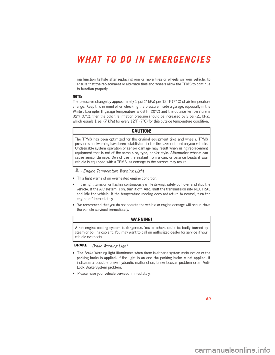
- Engine Temperature Warning Light
• This light warns of an overheated engine condition.
• If the light turns on or flashes continuously while driving, safely pull over and stop the vehicle. If the A/C system is on, turn it off. Also, shift the transmission into NEUTRAL
and idle the vehicle. If the temperature reading does not return to normal, turn the
engine off immediately.
• We recommend that you do not operate the vehicle or engine damage will occur. Have the vehicle serviced immediately.
WARNING!
A hot engine cooling system is dangerous. You or others could be badly burned by
steam or boiling coolant. You may want to call an authorized dealer for service if your
vehicle overheats.
BRAKE- Brake Warning Light
• The Brake Warning light illuminates when there is either a system malfunction or theparking brake is applied. If the light is on and the parking brake is not applied, it
indicates a possible brake hydraulic malfunction, brake booster problem or an Anti-
Lock Brake System problem.
• Please have your vehicle serviced immediately.
WHAT TO DO IN EMERGENCIES
69
Page 72 of 100
WARNING!
Driving a vehicle with the red brake light on is dangerous. Part of the brake system may
have failed. It will take longer to stop the vehicle. You could have a collision. Have the
vehicle checked immediately.
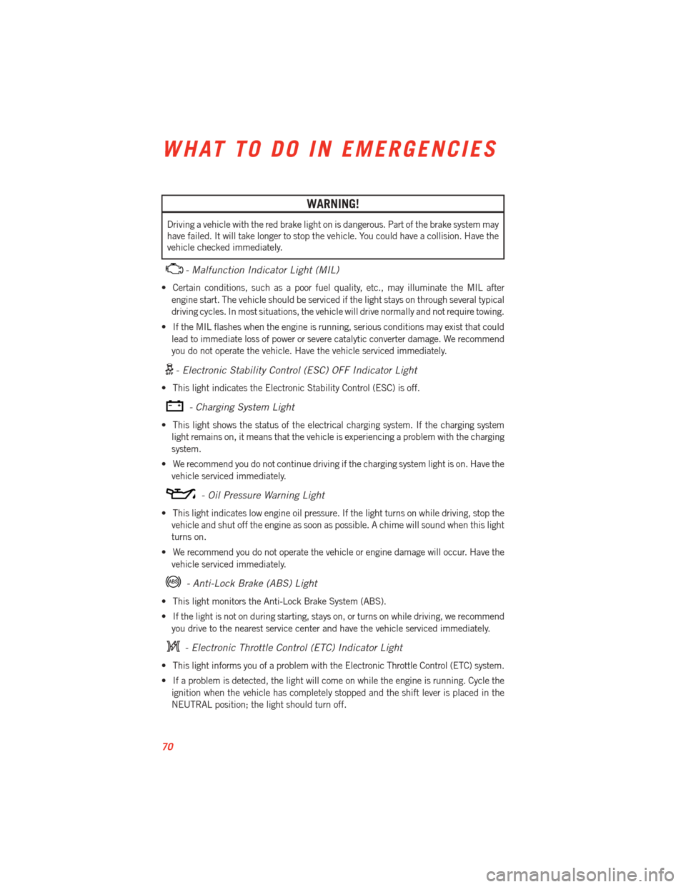
- Malfunction Indicator Light (MIL)
• Certain conditions, such as a poor fuel quality, etc., may illuminate the MIL afterengine start. The vehicle should be serviced if the light stays on through several typical
driving cycles. In most situations, the vehicle will drive normally and not require towing.
• If the MIL flashes when the engine is running, serious conditions may exist that could lead to immediate loss of power or severe catalytic converter damage. We recommend
you do not operate the vehicle. Have the vehicle serviced immediately.
- Electronic Stability Control (ESC) OFF Indicator Light
• This light indicates the Electronic Stability Control (ESC) is off.
- Charging System Light
• This light shows the status of the electrical charging system. If the charging systemlight remains on, it means that the vehicle is experiencing a problem with the charging
system.
• We recommend you do not continue driving if the charging system light is on. Have the vehicle serviced immediately.
- Oil Pressure Warning Light
• This light indicates low engine oil pressure. If the light turns on while driving, stop thevehicle and shut off the engine as soon as possible. A chime will sound when this light
turns on.
• We recommend you do not operate the vehicle or engine damage will occur. Have the vehicle serviced immediately.
- Anti-Lock Brake (ABS) Light
• This light monitors the Anti-Lock Brake System (ABS).
• If the light is not on during starting, stays on, or turns on while driving, we recommendyou drive to the nearest service center and have the vehicle serviced immediately.
- Electronic Throttle Control (ETC) Indicator Light
• This light informs you of a problem with the Electronic Throttle Control (ETC) system.
• If a problem is detected, the light will come on while the engine is running. Cycle theignition when the vehicle has completely stopped and the shift lever is placed in the
NEUTRAL position; the light should turn off.
WHAT TO DO IN EMERGENCIES
70
Page 73 of 100
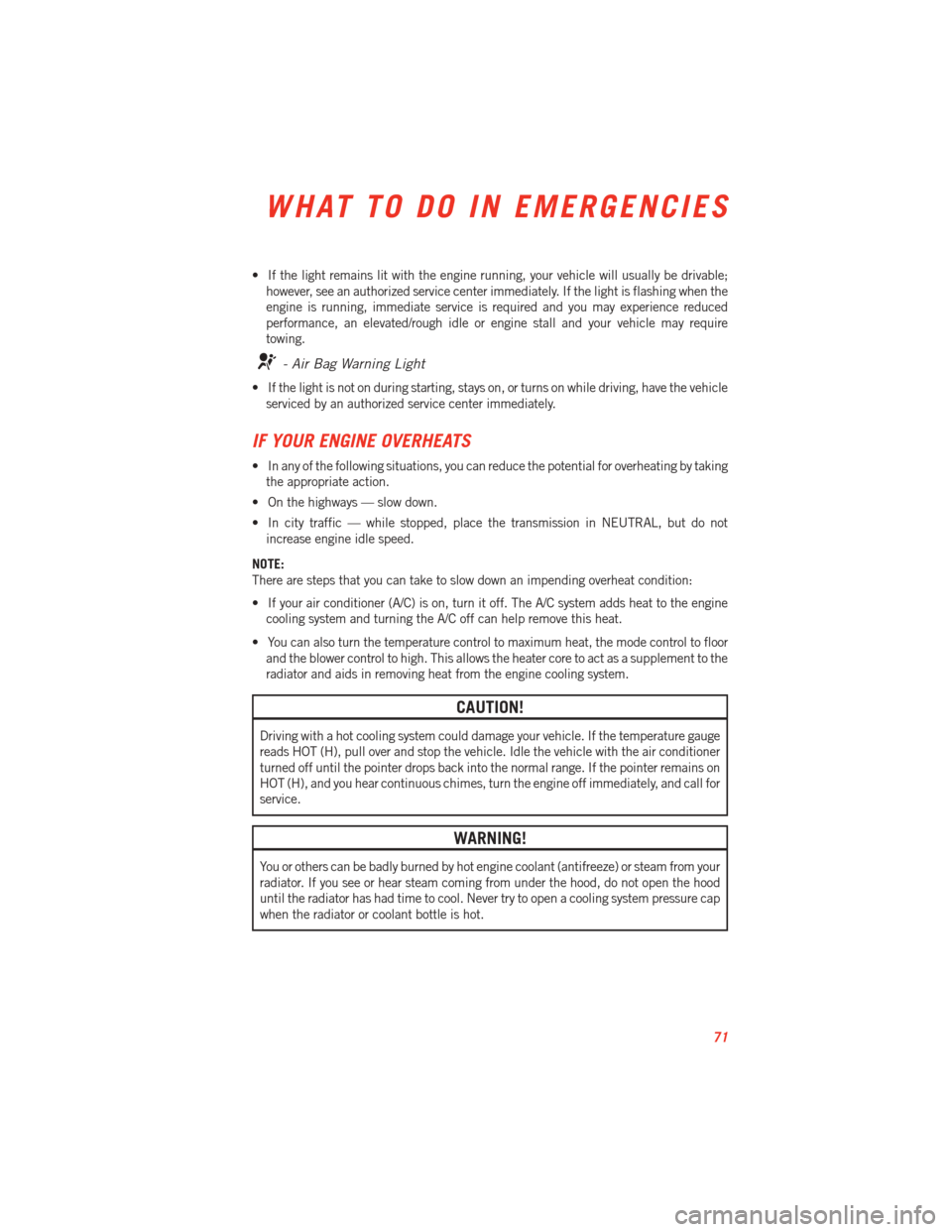
• If the light remains lit with the engine running, your vehicle will usually be drivable;however, see an authorized service center immediately. If the light is flashing when the
engine is running, immediate service is required and you may experience reduced
performance, an elevated/rough idle or engine stall and your vehicle may require
towing.
- Air Bag Warning Light
• If the light is not on during starting, stays on, or turns on while driving, have the vehicleserviced by an authorized service center immediately.
IF YOUR ENGINE OVERHEATS
• In any of the following situations, you can reduce the potential for overheating by takingthe appropriate action.
• On the highways — slow down.
• In city traffic — while stopped, place the transmission in NEUTRAL, but do not increase engine idle speed.
NOTE:
There are steps that you can take to slow down an impending overheat condition:
• If your air conditioner (A/C) is on, turn it off. The A/C system adds heat to the engine cooling system and turning the A/C off can help remove this heat.
• You can also turn the temperature control to maximum heat, the mode control to floor and the blower control to high. This allows the heater core to act as a supplement to the
radiator and aids in removing heat from the engine cooling system.
CAUTION!
Driving with a hot cooling system could damage your vehicle. If the temperature gauge
reads HOT (H), pull over and stop the vehicle. Idle the vehicle with the air conditioner
turned off until the pointer drops back into the normal range. If the pointer remains on
HOT (H), and you hear continuous chimes, turn the engine off immediately, and call for
service.
WARNING!
You or others can be badly burned by hot engine coolant (antifreeze) or steam from your
radiator. If you see or hear steam coming from under the hood, do not open the hood
until the radiator has had time to cool. Never try to open a cooling system pressure cap
when the radiator or coolant bottle is hot.
WHAT TO DO IN EMERGENCIES
71
Page 88 of 100
FUSES
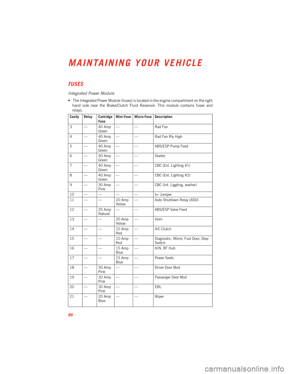
Integrated Power Module
• The Integrated Power Module (fuses) is located in the engine compartment on the righthand side near the Brake/Clutch Fluid Reservoir. This module contains fuses and
relays.
Cavity Relay Cartridge
FuseMini-Fuse Micro-Fuse Description
3 — 40 Amp Green— — Rad Fan
4 — 40 Amp Green— — Rad Fan Rly High
5 — 40 Amp Green— — ABS/ESP Pump Feed
6 — 40 Amp Green— — Starter
7 — 40 Amp Green— — CBC (Ext. Lighting #1)
8 — 40 Amp Green— — CBC (Ext. Lighting #2)
9 — 30 Amp Pink— — CBC (Int. Liggting, washer)
10 — — — — b+ Jumper
11 — — 20 Amp Yellow— Auto Shutdown Relay (ASD)
12 — 25 Amp Natural— — ABS/ESP Valve Feed
13 — — 20 Amp Yellow— Horn
14 — — 10 Amp Red— A/C Clutch
15 — — 10 Amp Red— Diagnostic, Mirror, Fuel Door, Stop
Switch
16 — — 15 Amp Blue— KIN,RFHub
17 — — 15 Amp Blue— Power Seats
18 — 30 Amp Pink— — Driver Door Mod
19 — 30 Amp Pink— — Passenger Door Mod
20 — 30 Amp Pink— — EBL
21 — 20 Amp Blue— — Wiper
MAINTAINING YOUR VEHICLE
86
Page 92 of 100
WHEEL AND WHEEL TRIM CARE
• All wheels and wheel trim, especially aluminum and chrome plated wheels, should becleaned regularly with a mild soap and water to prevent corrosion.
• To remove heavy soil and/or excessive brake dust, use MOPAR
®Wheel Cleaner or
equivalent or select a non-abrasive, non-acidic cleaner.
CAUTION!
Do not use scouring pads, steel wool, a bristle brush, or metal polishes. Do not use oven
cleaner. These products may damage the wheel's protective finish. Avoid automatic car
washes that use acidic solutions or harsh brushes that may damage the wheel's
protective finish. Only MOPAR
®Wheel Cleaner or equivalent is recommended.
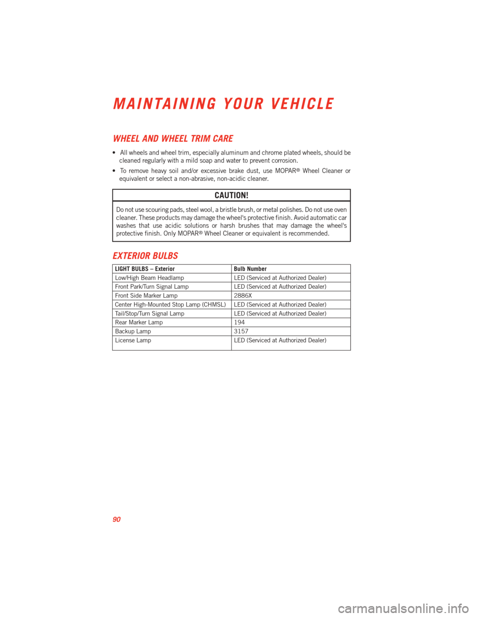
EXTERIOR BULBS
LIGHT BULBS – Exterior Bulb Number
Low/High Beam Headlamp LED (Serviced at Authorized Dealer)
Front Park/Turn Signal Lamp LED (Serviced at Authorized Dealer)
Front Side Marker Lamp 2886X
Center High-Mounted Stop Lamp (CHMSL) LED (Serviced at Authorized Dealer)
Tail/Stop/Turn Signal Lamp LED (Serviced at Authorized Dealer)
Rear Marker Lamp 194
Backup Lamp 3157
License Lamp LED (Serviced at Authorized Dealer)
MAINTAINING YOUR VEHICLE
90