brake DODGE VIPER 2015 VX / 3.G User Guide
[x] Cancel search | Manufacturer: DODGE, Model Year: 2015, Model line: VIPER, Model: DODGE VIPER 2015 VX / 3.GPages: 148, PDF Size: 21.7 MB
Page 5 of 148
VEHICLES SOLD IN CANADA
With respect to any vehicles sold in Canada, the name FCA US LLC shall be deemed to be
deleted and the name FCA Canada Inc. used in substitution (excluding legal lines).
WARNING!
•Pedalsthatcannotmovefreelycancauselossofvehiclecontrolandincreasethe
risk of serious personal injury.
•Alwaysmakesurethatobjectscannotfallintothedriverfootwellwhilethevehicle
is moving. Objects can become trapped under the brake pedal and accelerator
pedal causing a loss of vehicle control.
•Failuretoproperlyfollowfloormatinstallationormountingcancauseinterference
with the brake pedal and accelerator pedal operation causing loss of control of the
vehicle.
•Never leave children alone in a vehicle, or with access to an unlocked vehicle. Allowing
children to be in a vehicle unattended is dangerous for a number of reasons. A child or
others could be seriously or fatally injured. Children should be warned not to touch the
parking brake, brake pedal or the shift lever/transmission gear selector.
•Do not leave the key fob in or near the vehicle, or in a location accessible to children,
and do not leave the ignition of a vehicle equipped with Keyless Enter-N-Go™ in the
ACC or ON/RUN mode. A child could operate power windows, other controls, or move
the vehicle.
•Neverusethe“PARK”positionasasubstitutefortheparkingbrake.Alwaysapply
the parking brake fully when parked to guard against vehicle movement and
possible injury or damage.
•RefertoyourOwner'sManualontheDVDforfurtherdetails.
USE OF AFTERMARKET PRODUCTS (ELECTRONICS)
The use of aftermarket devices including cell phones, MP3 players, GPS systems, or
chargers may affect the performance of on-board wireless features including Keyless
Enter-N-Go™ and Remote Start range. If you are experiencing difficulties with any of your
wireless features, try disconnecting your aftermarket devices to see if the situation
improves. If your symptoms persist, please see an authorized dealer.
CHRYSLER, DODGE, JEEP, RAM, MOPAR and Uconnect are registered trademarks of
FCA US LLC.
COPYRIGHT ©2015 FCA US LLC
INTRODUCTION/WELCOME
3
Page 7 of 148
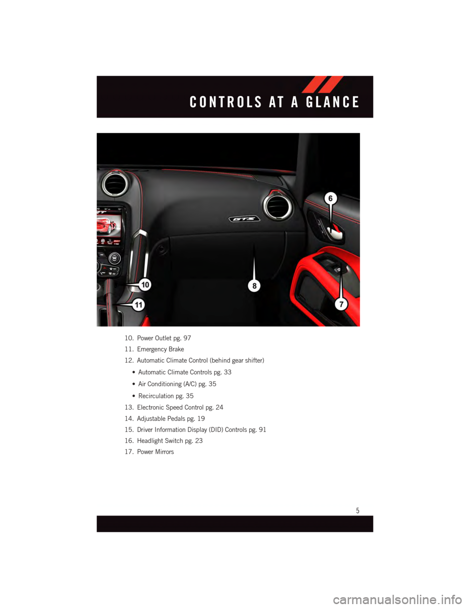
10. Power Outlet pg. 97
11. Emergency Brake
12. Automatic Climate Control (behind gear shifter)
•AutomaticClimateControlspg.33
•AirConditioning(A/C)pg.35
•Recirculationpg.35
13. Electronic Speed Control pg. 24
14. Adjustable Pedals pg. 19
15. Driver Information Display (DID) Controls pg. 91
16. Headlight Switch pg. 23
17. Power Mirrors
CONTROLS AT A GLANCE
5
Page 11 of 148
WARNING!
•Alwaysapplytheparkingbrakefullywhenparkedtoguardagainstvehiclemove-
ment and possible injury or damage.
•Never leave children alone in a vehicle, or with access to an unlocked vehicle. Allowing
children to be in a vehicle unattended is dangerous for a number of reasons. A child or
others could be seriously or fatally injured. Children should be warned not to touch the
parking brake, brake pedal or the transmission gear selector.
•Do not leave the Key Fob in or near the vehicle, or in a location accessible to children,
and do not leave the ignition of a vehicle equipped with Keyless Enter-N-Go™ in the
ACC or ON/RUN mode. A child could operate power windows, other controls, or move
the vehicle.
ENGINE STARTING/STOPPING
Starting
1. Fully apply the parking brake.
2. Push the clutch pedal to the floor.
3. Place the shift lever in NEUTRAL.
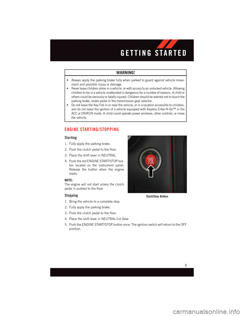
4. Push the red ENGINE START/STOP but-
ton located on the instrument panel.
Release the button when the engine
starts.
NOTE:
The engine will not start unless the clutch
pedal is pushed to the floor.
Stopping
1. Bring the vehicle to a complete stop.
2. Fully apply the parking brake.
3. Push the clutch pedal to the floor.
4. Place the shift lever in NEUTRAL/1st Gear.
5. Push the ENGINE START/STOP button once. The ignition switch will return to the OFF
position.
Start/Stop Button
GETTING STARTED
9
Page 27 of 148
To Decrease Speed
When the Electronic Speed Control is set, you can decrease speed by pushing the SET-
button.
The drivers preferred units can be selected through the instrument panel settings if
equipped. The speed decrement shown is dependant on the chosen speed unit of U.S.
(MPH) or Metric (km/h):
U.S. Speed (MPH)
•PushingtheSET-button once will result in a 1 MPH decrease in set speed. Each
subsequent tap of the button results in a decrease of 1 MPH.
•Ifthebuttoniscontinuallypushed,thesetspeedwillcontinuetodecreaseuntilthe
button is released, then the new set speed will be established.
Metric Speed (km/h)
•PushingtheSET-button once will result in a 1 km/h decrease in set speed. Each
subsequent tap of the button results in a decrease of 1 km/h.
•Ifthebuttoniscontinuallypushed,thesetspeedwillcontinuetodecreaseuntilthe
button is released, then the new set speed will be established.
Resume
To r e s u m e a p r e v i o u s l y s e l e c t e d s e t s p e e d i n m e m o r y, p u s h t h e R E S + b u t t o n a n d r e l e a s e .
Cancel
Push the CANCEL button, or apply the brakes to cancel the set speed and maintain the set
speed memory.
Push the ON/OFF button to turn the system off and erase the set speed memory.
WARNING!
•LeavingtheElectronicSpeedControlsystemonwhennotinuseisdangerous.You
could accidentally set the system or cause it to go faster than you want. You could
lose control and have a collision. Always leave the Electronic Speed Control system
off when you are not using it.
•ElectronicSpeedControlcanbedangerouswherethesystemcannotmaintaina
constant speed. Your vehicle could go too fast for the conditions, and you could lose
control. A collision could be the result. Do not use Electronic Speed Control in
heavy traffic or on roads that are winding, icy, snow-covered or slippery.
OPERATING YOUR VEHICLE
25
Page 28 of 148
LAUNCH MODE
This system maximizes acceleration traction for straight line racing.
1. Bring the vehicle to complete stop on a level track surface with the engine running.
2. Set the steering wheel for straight ahead driving.
3. Fully depress the clutch and select the first gear position.
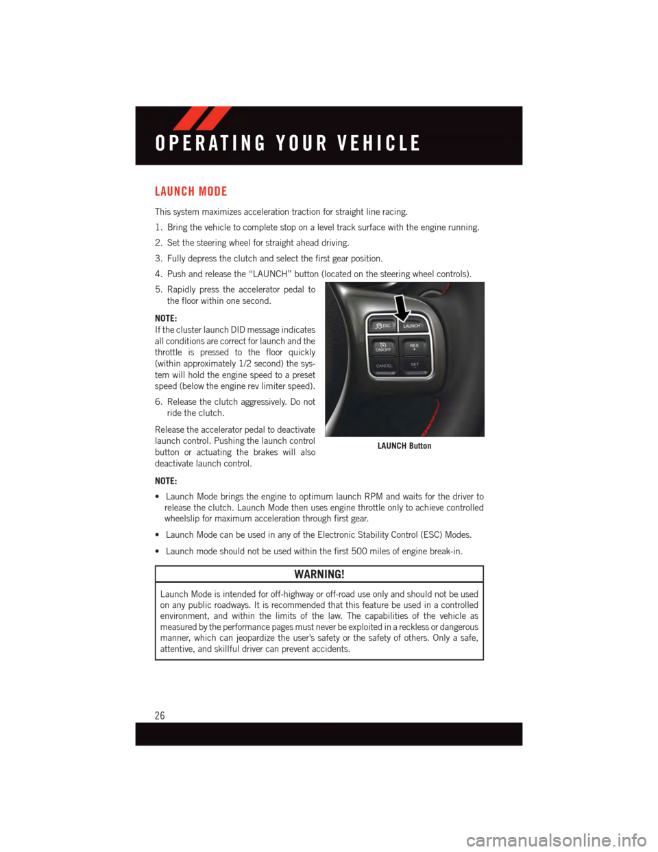
4. Push and release the “LAUNCH” button (located on the steering wheel controls).
5. Rapidly press the accelerator pedal to
the floor within one second.
NOTE:
If the cluster launch DID message indicates
all conditions are correct for launch and the
throttle is pressed to the floor quickly
(within approximately 1/2 second) the sys-
tem will hold the engine speed to a preset
speed (below the engine rev limiter speed).
6. Release the clutch aggressively. Do not
ride the clutch.
Release the accelerator pedal to deactivate
launch control. Pushing the launch control
button or actuating the brakes will also
deactivate launch control.
NOTE:
•LaunchModebringstheenginetooptimumlaunchRPMandwaitsforthedriverto
release the clutch. Launch Mode then uses engine throttle only to achieve controlled
wheelslip for maximum acceleration through first gear.
•LaunchModecanbeusedinanyoftheElectronicStabilityControl(ESC)Modes.
•Launchmodeshouldnotbeusedwithinthefirst500milesofenginebreak-in.
WARNING!
Launch Mode is intended for off-highway or off-road use only and should not be used
on any public roadways. It is recommended that this feature be used in a controlled
environment, and within the limits of the law. The capabilities of the vehicle as
measured by the performance pages must never be exploited in a reckless or dangerous
manner, which can jeopardize the user’s safety or the safety of others. Only a safe,
attentive, and skillful driver can prevent accidents.
LAUNCH Button
OPERATING YOUR VEHICLE
26
Page 30 of 148
ELECTRONIC STABILITY CONTROL (ESC)
•TheESCcorrectsforoversteeringandundersteeringthevehiclebyapplyingthebrake
of the appropriate wheel. Engine power may also be reduced to assist in counteracting
the condition of oversteer or understeer and help the vehicle maintain the desired path.
•InfullonmodeESCutilizessensorsinthevehicletodeterminethepaththatthedriver
intends to steer the vehicle and compares it to the actual path of the vehicle. When the
actual path does not match the intended path, the ESC applies the brake of the
appropriate wheel to assist in counteracting the condition of oversteer or understeer.
Electronic Stability Control (ESC) Operating Modes
The ESC system may have five available operating modes:
ESC On
•ThisisthenormaloperatingmodefortheESCsystem.Wheneverthevehicleisstarted,
the ESC system will be in this mode. The ESC On mode should be used for most driving
situations. The ESC should only be turned OFF for specific reasons as noted in the
following paragraphs.
ESC Full Off
•TheESCOffmodeisintendedforoff-highwayoroff-roaduseonlyandshouldnotbeused on any public roadways. In this mode, all TCS and ESC stability features areturned OFF. To enter the “Full Off” mode, push and hold the “ESC Off” switch for fiveseconds while the vehicle is stopped with the engine running. After five seconds, achime will sound, the “ESC Activation/Malfunction Indicator Light” will illuminate, andthe “ESC OFF” message will display in the vehicle cluster (left of the odometer). The“ESC OFF” message may appear in the Driver Information Display (DID). To turn ESCON again, momentarily push the “ESC Off” switch.
Sport Mode
•Sportmodehasreducedtractioncontrolandreducedstabilitycontrol.Toenterthe
“Sport Mode” mode, push the “ESC” switch once (located on the steering wheel). The
“ESC SPORT” light will illuminate, and the “ESC SPORT” message will display in the
vehicle cluster (left of the odometer).
Track Mode
•Tr a c k M o d e h a s n o t r a c t i o n c o n t r o l a n d h a s r e d u c e d s t a b i l i t y c o n t r o l . To e n t e r t h e “ Tr a c k
Mode” mode, push the “ESC” switch twice. The “ESC TRACK” light will illuminate, and
the “ESC TRACK” message will display in the vehicle cluster (left of the odometer).
OPERATING YOUR VEHICLE
28
Page 101 of 148
ROADSIDE ASSISTANCE
Dial toll-free 1-800-521-2779 for U.S. Residents or 1-800-363-4869 for Canadian
Residents.
•Provideyourname,vehicleidentificationnumber,licenseplatenumber,andyour
location, including the telephone number from which you are calling.
•Brieflydescribethenatureoftheproblemandanswerafewsimplequestions.
•Youwillbegiventhenameoftheserviceproviderandanestimatedtimeofarrival.
If you feel you are in an “unsafe situation”, please let us know. With your consent, we
will contact local police or safety authorities.
INSTRUMENT CLUSTER WARNING LIGHTS
–LowFuelWarningLight
This warning light indicates when the fuel level reaches approximately 2.0 gal (7.8 L).
This light will turn on and a single chime will sound.
–ChargingSystemLight
This light shows the status of the electrical charging system. If the charging system light
remains on, it means that the vehicle is experiencing a problem with the charging system.
We recommend you do not continue driving if the charging system light is on. Have the
vehicle serviced immediately.
–OilPressureWarningLight
This light indicates low engine oil pressure. If the light turns on while driving, stop the
vehicle and shut off the engine as soon as possible. A chime will sound when this light
turns on.
We recommend you do not operate the vehicle or engine damage will occur. Have the
vehicle serviced immediately.
–Anti-LockBrake(ABS)Light
This light monitors the Anti-Lock Brake System (ABS).
If the light is not on during starting, stays on or turns on while driving, we recommend you
contact the nearest authorized dealer and have the vehicle serviced immediately.
–AirBagWarningLight
If the light is not on during starting, stays on, or turns on while driving, have the vehicle
serviced by an authorized dealer immediately.
WHAT TO DO IN EMERGENCIES
99
Page 104 of 148
–SeatBeltReminderLight
When the ignition switch is first turned to the ON/RUN position, this light will turn on for
four to eight seconds as a bulb check. During the bulb check, if the driver's seat belt is
unbuckled, a chime will sound. After the bulb check or when driving, if the driver or front
passenger seat belt remains unbuckled, the Seat Belt Indicator Light will flash or remain
on continuously. Refer to “Seat Belt Systems” in “Things To Know Before Starting” in your
Owner’s Manual on the DVD for further information.
–BrakeWarningLight
This light monitors various brake functions, including brake fluid level and parking brake
application. If the brake light turns on, it may indicate that the parking brake is applied,
that the brake fluid level is low, or that there is a problem with the anti-lock brake system
reservoir.
If the light remains on when the parking brake has been disengaged, and the fluid level is
at the full mark on the master cylinder reservoir, it indicates a possible brake hydraulic
system malfunction or that a problem with the Brake Booster has been detected by the
Anti-Lock Brake System (ABS)/Electronic Stability Control (ESC) system. In this case, the
light will remain on until the condition has been corrected. If the problem is related to the
brake booster, the ABS pump will run when applying the brake, and a brake pedal
pulsation may be felt during each stop.
The dual brake system provides a reserve braking capacity in the event of a failure to a portion
of the hydraulic system. A leak in either half of the dual brake system is indicated by the
Brake Warning Light, which will turn on when the brake fluid level in the master cylinder has
dropped below a specified level. The light will remain on until the cause is corrected.
Vehicles equipped with the Anti-Lock Brake System (ABS) are also equipped with Electronic
Brake Force Distribution (EBD). In the event of an EBD failure, the Brake Warning Light will
turn on along with the ABS Light. Immediate repair to the ABS system is required.
Operation of the Brake Warning Light can be checked by turning the ignition switch from the
OFF position to the ON/RUN position. The light should illuminate for approximately two
seconds. The light should then turn off unless the parking brake is applied or a brake fault is
detected. If the light does not illuminate, have the light inspected by an authorized dealer.
The light also will turn on when the parking brake is applied with the ignition switch in the
ON/RUN position.
NOTE:
This light shows only that the parking brake is applied. It does not show the degree of
brake application.
WHAT TO DO IN EMERGENCIES
102
Page 105 of 148
WARNING!
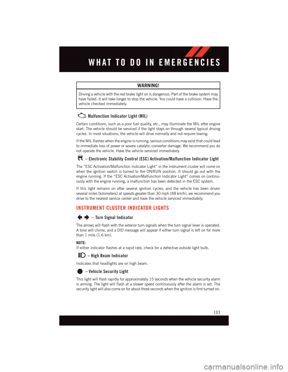
Driving a vehicle with the red brake light on is dangerous. Part of the brake system may
have failed. It will take longer to stop the vehicle. You could have a collision. Have the
vehicle checked immediately.
Malfunction Indicator Light (MIL)
Certain conditions, such as a poor fuel quality, etc., may illuminate the MIL after engine
start. The vehicle should be serviced if the light stays on through several typical driving
cycles. In most situations, the vehicle will drive normally and not require towing.
If the MIL flashes when the engine is running, serious conditions may exist that could lead
to immediate loss of power or severe catalytic converter damage. We recommend you do
not operate the vehicle. Have the vehicle serviced immediately.
–ElectronicStabilityControl(ESC)Activation/MalfunctionIndicatorLight
The “ESC Activation/Malfunction Indicator Light” in the instrument cluster will come on
when the ignition switch is turned to the ON/RUN position. It should go out with the
engine running. If the “ESC Activation/Malfunction Indicator Light” comes on continu-
ously with the engine running, a malfunction has been detected in the ESC system.
If this light remains on after several ignition cycles, and the vehicle has been driven
several miles (kilometers) at speeds greater than 30 mph (48 km/h), we recommend you
drive to the nearest service center and have the vehicle serviced immediately.
INSTRUMENT CLUSTER INDICATOR LIGHTS
–TurnSignalIndicator
The arrows will flash with the exterior turn signals when the turn signal lever is operated.
Atonewillchime,andaDIDmessagewillappearifeitherturnsignalisleftonformore
than 1 mile (1.6 km).
NOTE:
If either indicator flashes at a rapid rate, check for a defective outside light bulb.
–HighBeamIndicator
Indicates that headlights are on high beam.
–VehicleSecurityLight
This light will flash rapidly for approximately 15 seconds when the vehicle security alarm
is arming. The light will flash at a slower speed continuously after the alarm is set. The
security light will also come on for about three seconds when the ignition is first turned on.
WHAT TO DO IN EMERGENCIES
103
Page 108 of 148
Tire Service Kit Usage Precautions
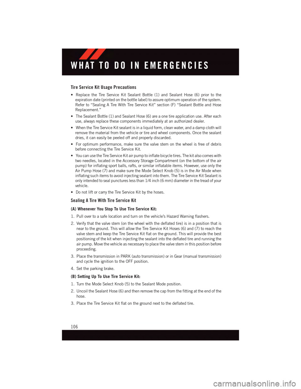
•ReplacetheTireServiceKitSealantBottle(1)andSealantHose(6)priortothe
expiration date (printed on the bottle label) to assure optimum operation of the system.
Refer to “Sealing A Tire With Tire Service Kit” section (F) “Sealant Bottle and Hose
Replacement.”
•TheSealantBottle(1)andSealantHose(6)areaonetireapplicationuse.Aftereach
use, always replace these components immediately at an authorized dealer.
•WhentheTireServiceKitsealantisinaliquidform,cleanwater,andadampclothwill
remove the material from the vehicle or tire and wheel components. Once the sealant
dries, it can easily be peeled off and properly discarded.
•Foroptimumperformance,makesurethevalvestemonthewheelisfreeofdebris
before connecting the Tire Service Kit.
•YoucanusetheTireServiceKitairpumptoinflatebicycletires.Thekitalsocomeswith
two needles, located in the Accessory Storage Compartment (on the bottom of the air
pump) for inflating sport balls, rafts, or similar inflatable items. However, use only the
Air Pump Hose (7) and make sure the Mode Select Knob (5) is in the Air Mode when
inflating such items to avoid injecting sealant into them. The Tire Service Kit Sealant is
only intended to seal punctures less than 1/4 inch (6 mm) diameter in the tread of your
vehicle.
•DonotliftorcarrytheTireServiceKitbythehoses.
Sealing A Tire With Tire Service Kit
(A) Whenever You Stop To Use Tire Service Kit:
1. Pull over to a safe location and turn on the vehicle’s Hazard Warning flashers.
2. Verify that the valve stem (on the wheel with the deflated tire) is in a position that is
near to the ground. This will allow the Tire Service Kit Hoses (6) and (7) to reach the
valve stem and keep the Tire Service Kit flat on the ground. This will provide the best
positioning of the kit when injecting the sealant into the deflated tire and running the
air pump. Move the vehicle as necessary to place the valve stem in this position before
proceeding.
3. Place the transmission in PARK (auto transmission) or in Gear (manual transmission)
and cycle the ignition to the OFF position.
4. Set the parking brake.
(B) Setting Up To Use Tire Service Kit:
1. Turn the Mode Select Knob (5) to the Sealant Mode position.
2. Uncoil the Sealant Hose (6) and then remove the cap from the fitting at the end of the
hose.
3. Place the Tire Service Kit flat on the ground next to the deflated tire.
WHAT TO DO IN EMERGENCIES
106