steering DODGE VIPER 2015 VX / 3.G User Guide
[x] Cancel search | Manufacturer: DODGE, Model Year: 2015, Model line: VIPER, Model: DODGE VIPER 2015 VX / 3.GPages: 148, PDF Size: 21.7 MB
Page 3 of 148
INTRODUCTION/WELCOME
WELCOME FROM FCA US LLC.......2
CONTROLS AT A GLANCE
DRIVER COCKPIT...............4INSTRUMENT CLUSTER...........6
GETTING STARTED
KEY FOB . . . . . . . . . . . . . . . . . . . . . 8ENGINE STARTING/STOPPING.......9VEHICLE SECURITY ALARM........10SEAT BELT SYSTEMS............11SUPPLEMENTAL RESTRAINTSYSTEM (SRS) — AIR BAGS........12CHILD RESTRAINTS............14NON-ADJUSTABLE HEAD RESTRAINTS...17FRONT SEATS................18ADJUSTABLE PEDALS...........19ADJUSTABLE FOOT REST..........20TILT STEERING COLUMN.........20
OPERATING YOUR VEHICLE
SRT ENGINE BREAK-INRECOMMENDATIONS............21TURN SIGNALS/WIPER/WASHER/HIGHBEAMS LEVER................22HEADLIGHT SWITCH............23ELECTRONIC SPEED CONTROL......24LAUNCH MODE................26ELECTRONIC CONTROL DAMPINGSYSTEM....................27ELECTRONIC STABILITY CONTROL(ESC)......................28MANUAL TRANSMISSION 1 TO 4 SKIPSHIFT.....................29ADDING FUEL................30AUTOMATIC TEMPERATURECONTROL (ATC)...............33PA R K V I E W®REAR BACK-UP CAMERA...35
ELECTRONICS
YOUR VEHICLE'S SOUND SYSTEM....36YOUR RADIO.................38Uconnect®ACCESS.............38Uconnect®8.4AN...............54Uconnect®8.4AN VOICE RECOGNITIONQUICK TIPS..................67Uconnect®PHONE..............82STEERING WHEEL AUDIO CONTROLS . . . 90DRIVER INFORMATION DISPLAY (DID) . . . 91PERFORMANCE PAGES...........93PROGRAMMABLE FEATURES.......94UNIVERSAL GARAGE DOOR OPENER(HomeLink®).................94POWER OUTLETS..............97
UTILITY
TRAILER TOWING WEIGHTS(MAXIMUM TRAILER WEIGHTRATINGS)...................98RECREATIONAL TOWING(BEHIND MOTORHOME, ETC.)......98
WHAT TO DO IN EMERGENCIES
ROADSIDE ASSISTANCE..........99INSTRUMENT CLUSTER WARNINGLIGHTS....................99INSTRUMENT CLUSTER INDICATORLIGHTS...................103IF YOUR ENGINE OVERHEATS......104TIRE SERVICE KIT.............105JUMP-STARTING..............111TOWING A DISABLED VEHICLE.....113FREEING A STUCK VEHICLE.......113EVENT DATA RECORDER (EDR).....114
MAINTAINING YOUR VEHICLE
OPENING THE HOOD...........115ENGINE COMPARTMENT.........116FLUID CAPACITIES............118FLUIDS, LUBRICANTS, ANDGENUINE PARTS..............118MAINTENANCE PROCEDURES......119MAINTENANCE SCHEDULES......120SRT – MAINTENANCE RECORD.....123FUSES....................124SUMMER/THREE-SEASON TIRES....126TIRE PRESSURES.............127SPARE TIRES — IF EQUIPPED......127WHEEL AND WHEEL TRIM CARE....129EXTERIOR BULBS.............129
CONSUMER ASSISTANCE
FCA US LLC CUSTOMER CENTER....130FCA CANADA INC. CUSTOMERCENTER...................130ASSISTANCE FOR THE HEARINGIMPAIRED..................130PUBLICATIONS ORDERING........130REPORTING SAFETY DEFECTS INTHE UNITED STATES............131
MOPAR® ACCESSORIES
AUTHENTIC ACCESSORIESBY MOPAR®.................132
FREQUENTLY ASKED QUESTIONS
FREQUENTLY ASKED QUESTIONS....133
INDEX.....................134
TABLE OF CONTENTS
Page 6 of 148
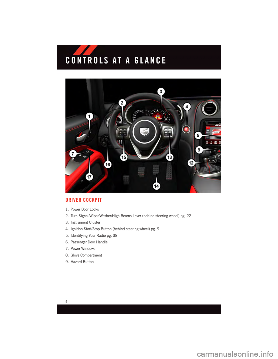
DRIVER COCKPIT
1. Power Door Locks
2. Turn Signal/Wiper/Washer/High Beams Lever (behind steering wheel) pg. 22
3. Instrument Cluster
4. Ignition Start/Stop Button (behind steering wheel) pg. 9
5. Identifying Your Radio pg. 38
6. Passenger Door Handle
7. Power Windows
8. Glove Compartment
9. Hazard Button
CONTROLS AT A GLANCE
4
Page 14 of 148
SUPPLEMENTAL RESTRAINT SYSTEM (SRS) — AIR BAGS
Air Bag System Components
Yo u r v e h i c l e m a y b e e q u i p p e d w i t h t h e f o l l o w i n g a i r b a g s y s t e m c o m p o n e n t s :
•OccupantRestraintController(ORC)
•AirBagWarningLight
•SteeringWheelandColumn
•InstrumentPanel
•KneeImpactBolsters
•AdvancedFrontAirBags
•SupplementalSideAirBags
•FrontandSideImpactSensors
•SeatBeltPretenioners
•SeatBeltBuckleSwitch
•SeatTrackPositionSensors
•OccupantClassificationSystem
Advanced Front Air Bags
•ThisvehiclehasAdvancedFrontAirBagsforboththedriverandfrontpassengerasa
supplement to the seat belt restraint systems. The Advanced Front Air Bags will not
deploy in every type of collision.
•AdvancedFrontAirBagsaredesignedtoprovideadditionalprotectionbysupplement-
ing the seat belts. Advanced Front Air Bags are not expected to reduce the risk of injury
in rear, side, or rollover collisions.
•TheAdvancedFrontAirBagswillnotdeployinallfrontalcollisions,includingsome
that may produce substantial vehicle damage — for example, some pole collisions,
truck underrides, and angle offset collisions.
•Ontheotherhand,dependingonthetypeandlocationofimpact,AdvancedFrontAir
Bags may deploy in crashes with little vehicle front-end damage but that produce a
severe initial deceleration.
•Becauseairbagsensorsmeasurevehicledecelerationovertime,vehiclespeedand
damage by themselves are not good indicators of whether or not an air bag should have
deployed.
•Seatbeltsarenecessaryforyourprotectioninallcollisions,andalsoareneededtohelp
keep you in position, away from an inflating air bag.
•Theairbagsmustbereadytoinflateforyourprotectioninacollision.TheOccupant
Restraint Controller (ORC) monitors the internal circuits and interconnecting wiring
associated with air bag system electrical components.
GETTING STARTED
12
Page 15 of 148
•TheORCturnsontheAirBagWarningLightintheinstrumentpanelforapproximately
four to eight seconds for a self-check when the ignition switch is first turned to the
ON/RUN position. After the self-check, the Air Bag Warning Light will turn off. If the
ORC detects a malfunction in any part of the system, it turns on the Air Bag Warning
Light, either momentarily or continuously. A single chime will sound to alert you if the
light comes on again after initial startup.
•TheORCmonitorsthereadinessoftheelectronicpartsoftheairbagsystemwhenever
the ignition switch is in the START or ON/RUN position. If the ignition switch is in the
OFF position or in the ACC position, the air bag system is not on and the air bags will
not inflate.
•IftheAirBagWarningLightintheinstrumentpanelisnotonduringthefourtoeight
seconds when the ignition switch is first turned to the ON/RUN position, stays on, or
turns on while driving, have the vehicle serviced by an authorized service center
immediately.
NOTE:
If the speedometer, tachometer, or any engine related gauges are not working, the
Occupant Restraint Controller (ORC) may also be disabled. In this condition the air bags
may not be ready to inflate for your protection. Have an authorized dealer service the air
bag system immediately.
•Afteranycollision,thevehicleshouldbetakentoanauthorizeddealerimmediately.
•Donotdriveyourvehicleaftertheairbagshavedeployed.Ifyouareinvolvedinanother
collision, the air bags will not be in place to protect you.
•Ifitisnecessarytomodifytheairbagsystemforpersonswithdisabilities,contactyour
authorized dealer.
•Referto“SupplementalRestraintSystem(SRS)”in“ThingsToKnowBeforeStarting
Yo u r Ve h i c l e ” i n t h e O w n e r ' s M a n u a l o n t h e D V D f o r f u r t h e r i n f o r m a t i o n .
WARNING!
•Relyingontheairbagsalonecouldleadtomoresevereinjuriesinacollision.The
air bags work with your seat belt to restrain you properly. In some collisions, the air
bags won't deploy at all. Always wear your seat belts even though you have air bags.
•BeingtooclosetothesteeringwheelorinstrumentpanelduringAdvancedFrontAir
Bag deployment could cause serious injury, including death. Air bags need room to
inflate. Sit back, comfortably extending your arms to reach the steering wheel or
instrument panel.
•Noobjectsshouldbeplacedoverorneartheairbagontheinstrumentpanelor
steering wheel because any such objects could cause harm if the vehicle is in a
collision severe enough to cause the air bag to inflate.
GETTING STARTED
13
Page 21 of 148
CAUTION!
Do not place any article under a power seat or impede its ability to move as it may cause
damage to the seat controls. Seat travel may become limited if movement is stopped
by an obstruction in the seat's path.
WARNING!
•Adjusting a seat while the vehicle is moving is dangerous. The sudden movement of
the seat could cause you to lose control. The seat belt might not be properly adjusted,
and you could be severely injured or killed. Only adjust a seat while the vehicle is
parked.
•Donotridewiththeseatbackreclinedsothattheseatbeltisnolongerresting
against your chest. In a collision, you could slide under the seat belt and be severely
injured or killed. Use the recliner only when the vehicle is parked.
ADJUSTABLE PEDALS
•Theadjustablepedalscanbemovedinanypositionoftheenginestart/stopbutton
(OFF/ACC/RUN).
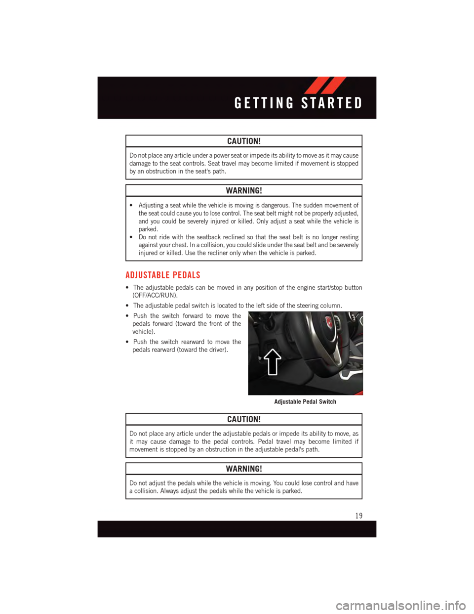
•Theadjustablepedalswitchislocatedtotheleftsideofthesteeringcolumn.
•Pushtheswitchforwardtomovethe
pedals forward (toward the front of the
vehicle).
•Pushtheswitchrearwardtomovethe
pedals rearward (toward the driver).
CAUTION!
Do not place any article under the adjustable pedals or impede its ability to move, as
it may cause damage to the pedal controls. Pedal travel may become limited if
movement is stopped by an obstruction in the adjustable pedal's path.
WARNING!
Do not adjust the pedals while the vehicle is moving. You could lose control and have
acollision.Alwaysadjustthepedalswhilethevehicleisparked.
Adjustable Pedal Switch
GETTING STARTED
19
Page 22 of 148
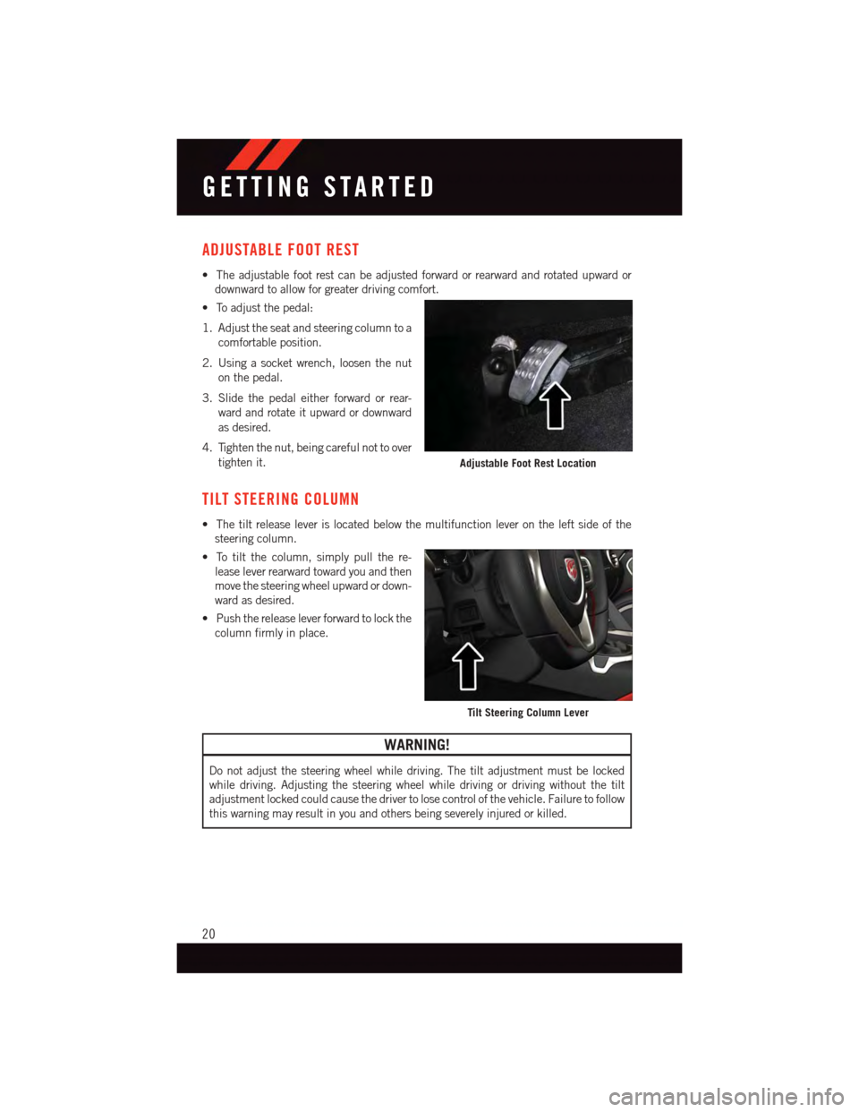
ADJUSTABLE FOOT REST
•Theadjustablefootrestcanbeadjustedforwardorrearwardandrotatedupwardor
downward to allow for greater driving comfort.
•Toadjustthepedal:
1. Adjust the seat and steering column to a
comfortable position.
2. Using a socket wrench, loosen the nut
on the pedal.
3. Slide the pedal either forward or rear-
ward and rotate it upward or downward
as desired.
4. Tighten the nut, being careful not to over
tighten it.
TILT STEERING COLUMN
•Thetiltreleaseleverislocatedbelowthemultifunctionleverontheleftsideofthe
steering column.
•Totiltthecolumn,simplypullthere-
lease lever rearward toward you and then
move the steering wheel upward or down-
ward as desired.
•Pushthereleaseleverforwardtolockthe
column firmly in place.
WARNING!
Do not adjust the steering wheel while driving. The tilt adjustment must be locked
while driving. Adjusting the steering wheel while driving or driving without the tilt
adjustment locked could cause the driver to lose control of the vehicle. Failure to follow
this warning may result in you and others being severely injured or killed.
Adjustable Foot Rest Location
Tilt Steering Column Lever
GETTING STARTED
20
Page 25 of 148
HEADLIGHT SWITCH
Automatic Headlights/Parking Lights/Headlights
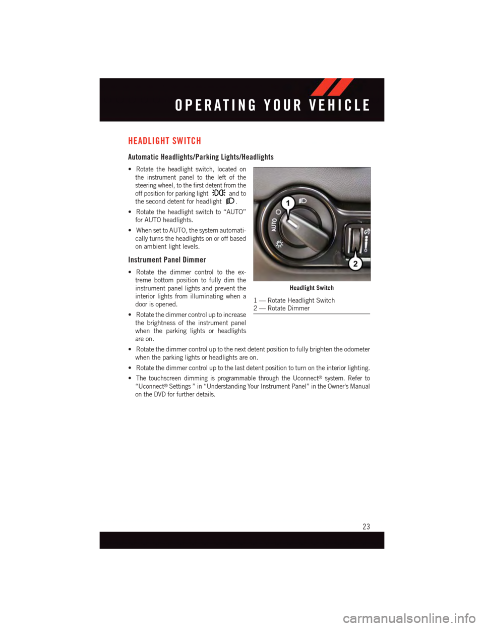
•Rotate the headlight switch, located on
the instrument panel to the left of the
steering wheel, to the first detent from the
off position for parking lightand to
the second detent for headlight.
•Rotatetheheadlightswitchto“AUTO”
for AUTO headlights.
•WhensettoAUTO,thesystemautomati-
cally turns the headlights on or off based
on ambient light levels.
Instrument Panel Dimmer
•Rotatethedimmercontroltotheex-
treme bottom position to fully dim the
instrument panel lights and prevent the
interior lights from illuminating when a
door is opened.
•Rotatethedimmercontroluptoincrease
the brightness of the instrument panel
when the parking lights or headlights
are on.
•Rotatethedimmercontroluptothenextdetentpositiontofullybrightentheodometer
when the parking lights or headlights are on.
•Rotatethedimmercontroluptothelastdetentpositiontoturnontheinteriorlighting.
•The touchscreen dimming is programmable through the Uconnect®system. Refer to
“Uconnect®Settings ” in “Understanding Your Instrument Panel” in the Owner's Manual
on the DVD for further details.
Headlight Switch
1—RotateHeadlightSwitch2—RotateDimmer
OPERATING YOUR VEHICLE
23
Page 26 of 148
ELECTRONIC SPEED CONTROL
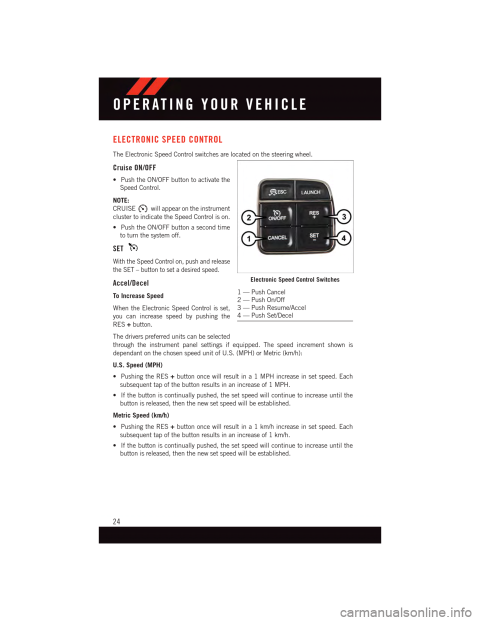
The Electronic Speed Control switches are located on the steering wheel.
Cruise ON/OFF
•PushtheON/OFFbuttontoactivatethe
Speed Control.
NOTE:
CRUISEwill appear on the instrument
cluster to indicate the Speed Control is on.
•PushtheON/OFFbuttonasecondtime
to turn the system off.
SET
With the Speed Control on, push and release
the SET – button to set a desired speed.
Accel/Decel
To Increase Speed
When the Electronic Speed Control is set,
you can increase speed by pushing the
RES+button.
The drivers preferred units can be selected
through the instrument panel settings if equipped. The speed increment shown is
dependant on the chosen speed unit of U.S. (MPH) or Metric (km/h):
U.S. Speed (MPH)
•PushingtheRES+button once will result in a 1 MPH increase in set speed. Each
subsequent tap of the button results in an increase of 1 MPH.
•Ifthebuttoniscontinuallypushed,thesetspeedwillcontinuetoincreaseuntilthe
button is released, then the new set speed will be established.
Metric Speed (km/h)
•PushingtheRES+button once will result in a 1 km/h increase in set speed. Each
subsequent tap of the button results in an increase of 1 km/h.
•Ifthebuttoniscontinuallypushed,thesetspeedwillcontinuetoincreaseuntilthe
button is released, then the new set speed will be established.
Electronic Speed Control Switches
1—PushCancel2—PushOn/Off3—PushResume/Accel4—PushSet/Decel
OPERATING YOUR VEHICLE
24
Page 28 of 148
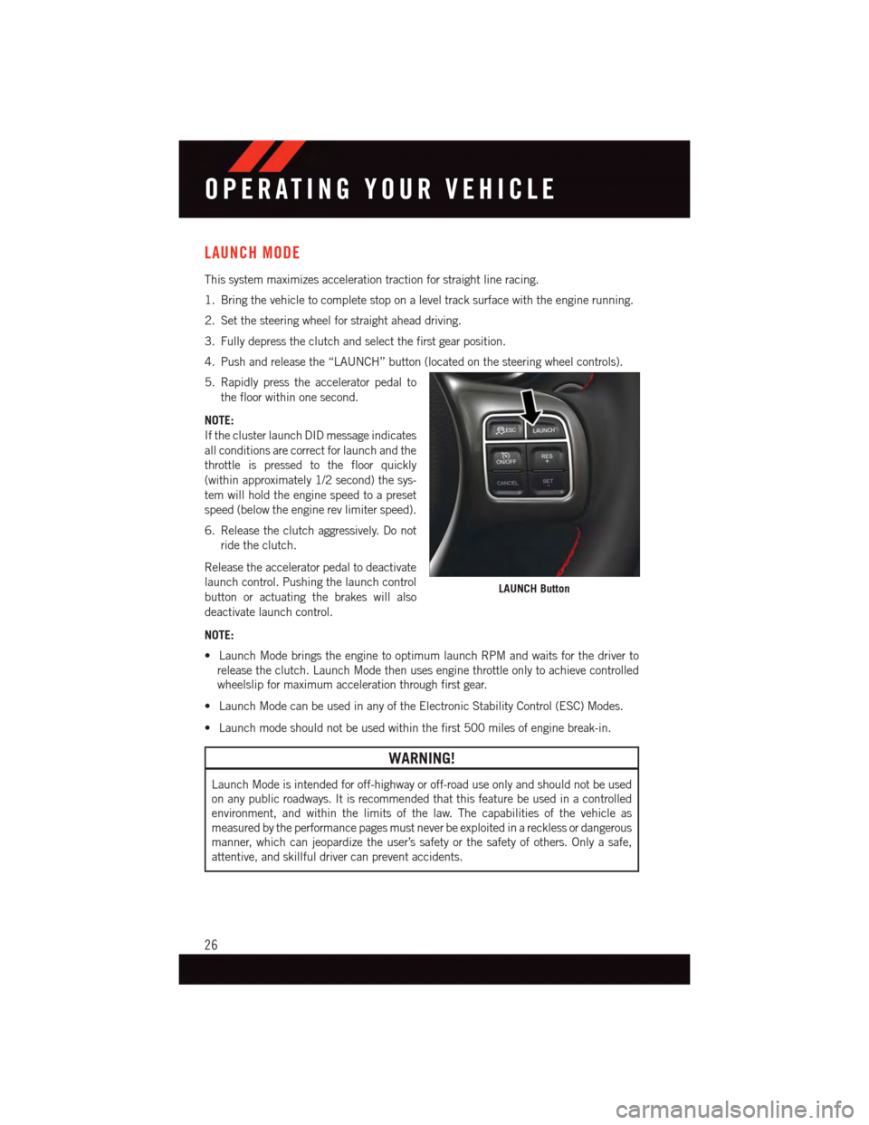
LAUNCH MODE
This system maximizes acceleration traction for straight line racing.
1. Bring the vehicle to complete stop on a level track surface with the engine running.
2. Set the steering wheel for straight ahead driving.
3. Fully depress the clutch and select the first gear position.
4. Push and release the “LAUNCH” button (located on the steering wheel controls).
5. Rapidly press the accelerator pedal to
the floor within one second.
NOTE:
If the cluster launch DID message indicates
all conditions are correct for launch and the
throttle is pressed to the floor quickly
(within approximately 1/2 second) the sys-
tem will hold the engine speed to a preset
speed (below the engine rev limiter speed).
6. Release the clutch aggressively. Do not
ride the clutch.
Release the accelerator pedal to deactivate
launch control. Pushing the launch control
button or actuating the brakes will also
deactivate launch control.
NOTE:
•LaunchModebringstheenginetooptimumlaunchRPMandwaitsforthedriverto
release the clutch. Launch Mode then uses engine throttle only to achieve controlled
wheelslip for maximum acceleration through first gear.
•LaunchModecanbeusedinanyoftheElectronicStabilityControl(ESC)Modes.
•Launchmodeshouldnotbeusedwithinthefirst500milesofenginebreak-in.
WARNING!
Launch Mode is intended for off-highway or off-road use only and should not be used
on any public roadways. It is recommended that this feature be used in a controlled
environment, and within the limits of the law. The capabilities of the vehicle as
measured by the performance pages must never be exploited in a reckless or dangerous
manner, which can jeopardize the user’s safety or the safety of others. Only a safe,
attentive, and skillful driver can prevent accidents.
LAUNCH Button
OPERATING YOUR VEHICLE
26
Page 30 of 148
ELECTRONIC STABILITY CONTROL (ESC)
•TheESCcorrectsforoversteeringandundersteeringthevehiclebyapplyingthebrake
of the appropriate wheel. Engine power may also be reduced to assist in counteracting
the condition of oversteer or understeer and help the vehicle maintain the desired path.
•InfullonmodeESCutilizessensorsinthevehicletodeterminethepaththatthedriver
intends to steer the vehicle and compares it to the actual path of the vehicle. When the
actual path does not match the intended path, the ESC applies the brake of the
appropriate wheel to assist in counteracting the condition of oversteer or understeer.
Electronic Stability Control (ESC) Operating Modes
The ESC system may have five available operating modes:
ESC On
•ThisisthenormaloperatingmodefortheESCsystem.Wheneverthevehicleisstarted,
the ESC system will be in this mode. The ESC On mode should be used for most driving
situations. The ESC should only be turned OFF for specific reasons as noted in the
following paragraphs.
ESC Full Off
•TheESCOffmodeisintendedforoff-highwayoroff-roaduseonlyandshouldnotbeused on any public roadways. In this mode, all TCS and ESC stability features areturned OFF. To enter the “Full Off” mode, push and hold the “ESC Off” switch for fiveseconds while the vehicle is stopped with the engine running. After five seconds, achime will sound, the “ESC Activation/Malfunction Indicator Light” will illuminate, andthe “ESC OFF” message will display in the vehicle cluster (left of the odometer). The“ESC OFF” message may appear in the Driver Information Display (DID). To turn ESCON again, momentarily push the “ESC Off” switch.
Sport Mode
•Sportmodehasreducedtractioncontrolandreducedstabilitycontrol.Toenterthe
“Sport Mode” mode, push the “ESC” switch once (located on the steering wheel). The
“ESC SPORT” light will illuminate, and the “ESC SPORT” message will display in the
vehicle cluster (left of the odometer).
Track Mode
•Tr a c k M o d e h a s n o t r a c t i o n c o n t r o l a n d h a s r e d u c e d s t a b i l i t y c o n t r o l . To e n t e r t h e “ Tr a c k
Mode” mode, push the “ESC” switch twice. The “ESC TRACK” light will illuminate, and
the “ESC TRACK” message will display in the vehicle cluster (left of the odometer).
OPERATING YOUR VEHICLE
28