steering wheel FIAT 124 SPIDER 2017 2.G Owner's Manual
[x] Cancel search | Manufacturer: FIAT, Model Year: 2017, Model line: 124 SPIDER, Model: FIAT 124 SPIDER 2017 2.GPages: 300, PDF Size: 121.24 MB
Page 192 of 300
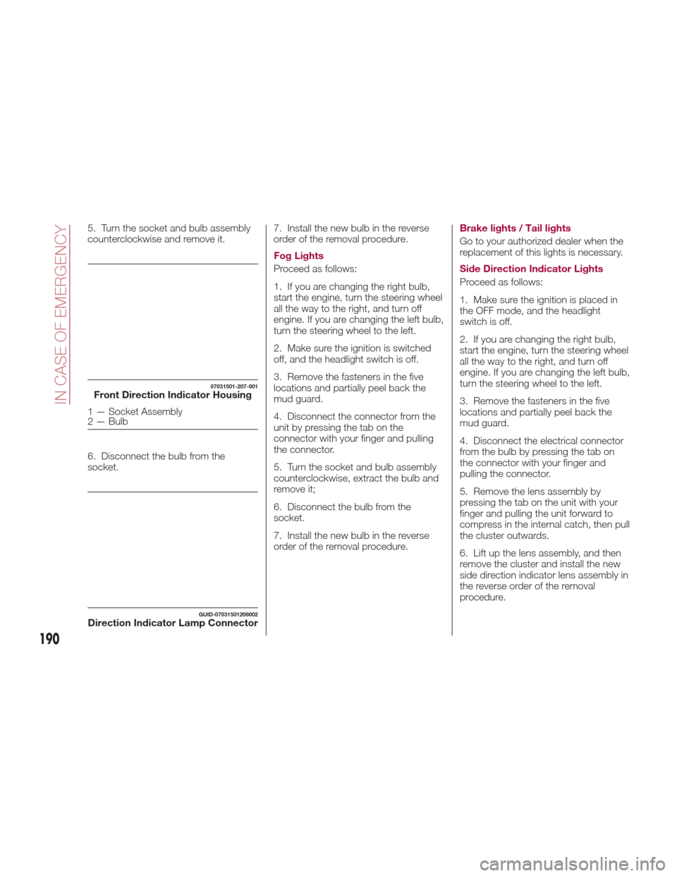
5. Turn the socket and bulb assembly
counterclockwise and remove it.
6. Disconnect the bulb from the
socket.7. Install the new bulb in the reverse
order of the removal procedure.
Fog Lights
Proceed as follows:
1. If you are changing the right bulb,
start the engine, turn the steering wheel
all the way to the right, and turn off
engine. If you are changing the left bulb,
turn the steering wheel to the left.
2. Make sure the ignition is switched
off, and the headlight switch is off.
3. Remove the fasteners in the five
locations and partially peel back the
mud guard.
4. Disconnect the connector from the
unit by pressing the tab on the
connector with your finger and pulling
the connector.
5. Turn the socket and bulb assembly
counterclockwise, extract the bulb and
remove it;
6. Disconnect the bulb from the
socket.
7. Install the new bulb in the reverse
order of the removal procedure.Brake lights / Tail lights
Go to your authorized dealer when the
replacement of this lights is necessary.
Side Direction Indicator Lights
Proceed as follows:
1. Make sure the ignition is placed in
the OFF mode, and the headlight
switch is off.
2. If you are changing the right bulb,
start the engine, turn the steering wheel
all the way to the right, and turn off
engine. If you are changing the left bulb,
turn the steering wheel to the left.
3. Remove the fasteners in the five
locations and partially peel back the
mud guard.
4. Disconnect the electrical connector
from the bulb by pressing the tab on
the connector with your finger and
pulling the connector.
5. Remove the lens assembly by
pressing the tab on the unit with your
finger and pulling the unit forward to
compress in the internal catch, then pull
the cluster outwards.
6. Lift up the lens assembly, and then
remove the cluster and install the new
side direction indicator lens assembly in
the reverse order of the removal
procedure.
07031501-207-001Front Direction Indicator Housing
1 — Socket Assembly
2 — Bulb
GUID-07031501208002Direction Indicator Lamp Connector
190
IN CASE OF EMERGENCY
Page 215 of 300
Warning!
Never use the air compressor above
43.5 psi (3 Bar). Using the air compressor
at an inflation pressure above 3 Bar
(43.5 psi) continuously is dangerous. If the
air compressor overheats, hot air will be
exhausted and you could get burned.
Caution!
If the tire inflation pressure does not
increase, repair of the tire is not possible. If
the tire does not reach the specified tire
inflation pressure within 10 minutes, it may
have received extensive damage. In this
case, the repair using the tire service kit
was not successful.
Do not operate the air compressor for a
continuous 10 minutes or longer because
using it for long periods could cause a
malfunction.
13. Adhere the speed restriction sticker
to an area where it can be viewed easily
by the driver.
Warning!
Do not adhere the speed restriction sticker
to the padded area on the steering wheel.
Adhering the speed restriction sticker to
the padded area on the steering wheel is
dangerous because the air bag may not
operate (deploy) normally resulting in
serious injury. In addition, do not adhere
the sticker to areas where warning lights or
the speedometer cannot be viewed.
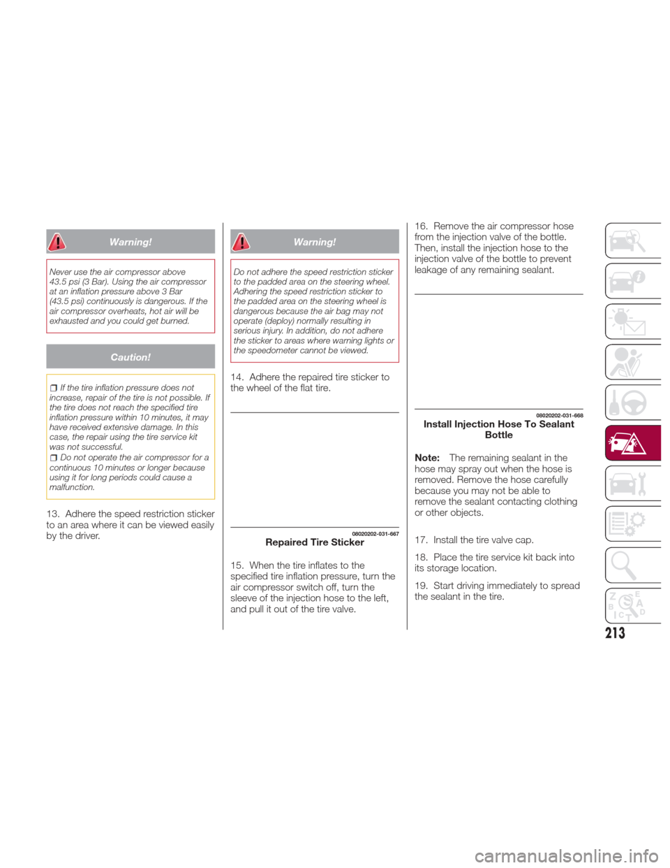
14. Adhere the repaired tire sticker to
the wheel of the flat tire.
15. When the tire inflates to the
specified tire inflation pressure, turn the
air compressor switch off, turn the
sleeve of the injection hose to the left,
and pull it out of the tire valve. 16. Remove the air compressor hose
from the injection valve of the bottle.
Then, install the injection hose to the
injection valve of the bottle to prevent
leakage of any remaining sealant.
Note:
The remaining sealant in the
hose may spray out when the hose is
removed. Remove the hose carefully
because you may not be able to
remove the sealant contacting clothing
or other objects.
17. Install the tire valve cap.
18. Place the tire service kit back into
its storage location.
19. Start driving immediately to spread
the sealant in the tire.
08020202-031-667Repaired Tire Sticker
08020202-031-668Install Injection Hose To Sealant Bottle
213
Page 219 of 300
13. Reinsert the valve core into the
valve and turn it clockwise to install.
Note:
The tire sealant cannot be reused.
If the tire sealant kit has been used, or
is expired, purchase new one at an
Authorized Dealer.
Do not throw away the empty tire
sealant bottle after use. Return the
empty tire sealant bottle to an
Authorized Dealer when replacing the
tire. The empty tire sealant bottle will
need to be used to extract and dispose
of the used sealant from the tire.
14. Install the injection hose to the tab
of the bottle to prevent leakage of any
remaining sealant.
15. Adhere the speed restriction sticker
to an area where it can be viewed easily
by the driver.
Warning!
Do not adhere the speed restriction sticker
to the padded area on the steering wheel.
Adhering the speed restriction sticker to
the padded area on the steering wheel is
dangerous because the air bag may not
operate (deploy) normally resulting in
serious injury. In addition, do not adhere
the sticker to areas where warning lights or
the speedometer cannot be viewed.
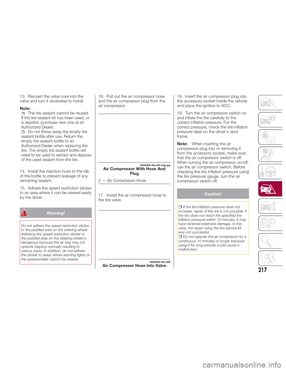
16. Pull out the air compressor hose
and the air compressor plug from the
air compressor.
17. Install the air compressor hose to
the tire valve. 18. Insert the air compressor plug into
the accessory socket inside the vehicle
and place the ignition to ACC.
19. Turn the air compressor switch on
and inflate the tire carefully to the
correct inflation pressure. For the
correct pressure, check the tire inflation
pressure label on the driver's door
frame.
Note:
When inserting the air
compressor plug into or removing it
from the accessory socket, make sure
that the air compressor switch is off.
When turning the air compressor on/off,
use the air compressor switch. Before
checking the tire inflation pressure using
the tire pressure gauge, turn the air
compressor switch off.
Caution!
If the tire inflation pressure does not
increase, repair of the tire is not possible. If
the tire does not reach the specified tire
inflation pressure within 10 minutes, it may
have received extensive damage. In this
case, the repair using the tire service kit
was not successful.
Do not operate the air compressor for a
continuous 10 minutes or longer because
using it for long periods could cause a
malfunction.
08020202-36A-004-high.jpgAir Compressor With Hose And Plug
2 — Air Compressor Hose
08020202-03A-00BAir Compressor Hose Into Valve
217
Page 225 of 300
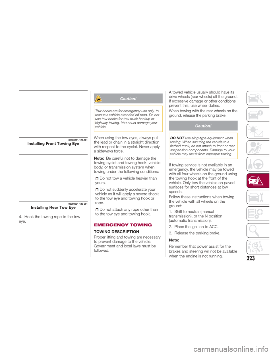
4. Hook the towing rope to the tow
eye.
Caution!
Tow hooks are for emergency use only, to
rescue a vehicle stranded off road. Do not
use tow hooks for tow truck hookup or
highway towing. You could damage your
vehicle.
When using the tow eyes, always pull
the lead or chain in a straight direction
with respect to the eyelet. Never apply
a sideways force.
Note:Be careful not to damage the
towing eyelet and towing hook, vehicle
body, or transmission system when
towing under the following conditions:
Do not tow a vehicle heavier than
yours.
Do not suddenly accelerate your
vehicle as it will apply a severe shock
to the tow eye and towing hook or
rope.
Do not attach any rope other than
to the tow eye and towing hook.
EMERGENCY TOWING
TOWING DESCRIPTION
Proper lifting and towing are necessary
to prevent damage to the vehicle.
Government and local laws must be
followed.
A towed vehicle usually should have its
drive wheels (rear wheels) off the ground.
If excessive damage or other conditions
prevent this, use wheel dollies.
When towing with the rear wheels on the
ground, release the parking brake.
Caution!
DO NOT use sling-type equipment when
towing. When securing the vehicle to a
flatbed truck, do not attach to front or rear
suspension components. Damage to your
vehicle may result from improper towing.
If towing service is not available in an
emergency, the vehicle may be towed
with all four wheels on the ground using
the towing hook at the front of the
vehicle. Only tow the vehicle on paved
surfaces for short distances at low
speeds.
Follow these instructions when towing
the vehicle with all wheels on the
ground:
1. Shift to neutral (manual
transmission), or the N position
(automatic transmission).
2. Place the ignition to ACC.
3. Release the parking brake.
Note:
Remember that power assist for the
brakes and steering will not be available
when the engine is not running.
08060201-121-001Installing Front Towing Eye
08060201-122-001Installing Rear Tow Eye
223
Page 230 of 300
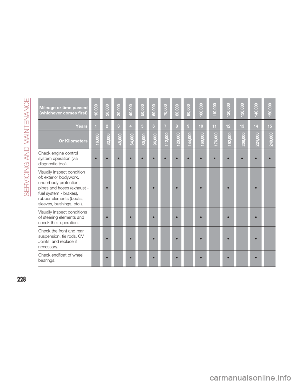
Mileage or time passed(whichever comes first)
10,000
20,000
30,000
40,000
50,000
60,000
70,000
80,000
90,000
100,000
110,000
120,000
130,000
140,000
150,000
Years123 456789101112131415
Or Kilometers16,000
32,000
48,000
64,000
80,000
96,000
112,000
128,000
144,000
160,000
176,000
192,000
208,000
224,000
240,000
Check engine control
system operation (via
diagnostic tool). •••••••••••••••
Visually inspect condition
of: exterior bodywork,
underbody protection,
pipes and hoses (exhaust -
fuel system - brakes),
rubber elements (boots,
sleeves, bushings, etc.). •••• • • •
Visually inspect conditions
of steering elements and
check their operation. •••• • • •
Check the front and rear
suspension, tie rods, CV
Joints, and replace if
necessary. •••• • • •
Check endfloat of wheel
bearings. •••• • • •
228
SERVICING AND MAINTENANCE
Page 249 of 300
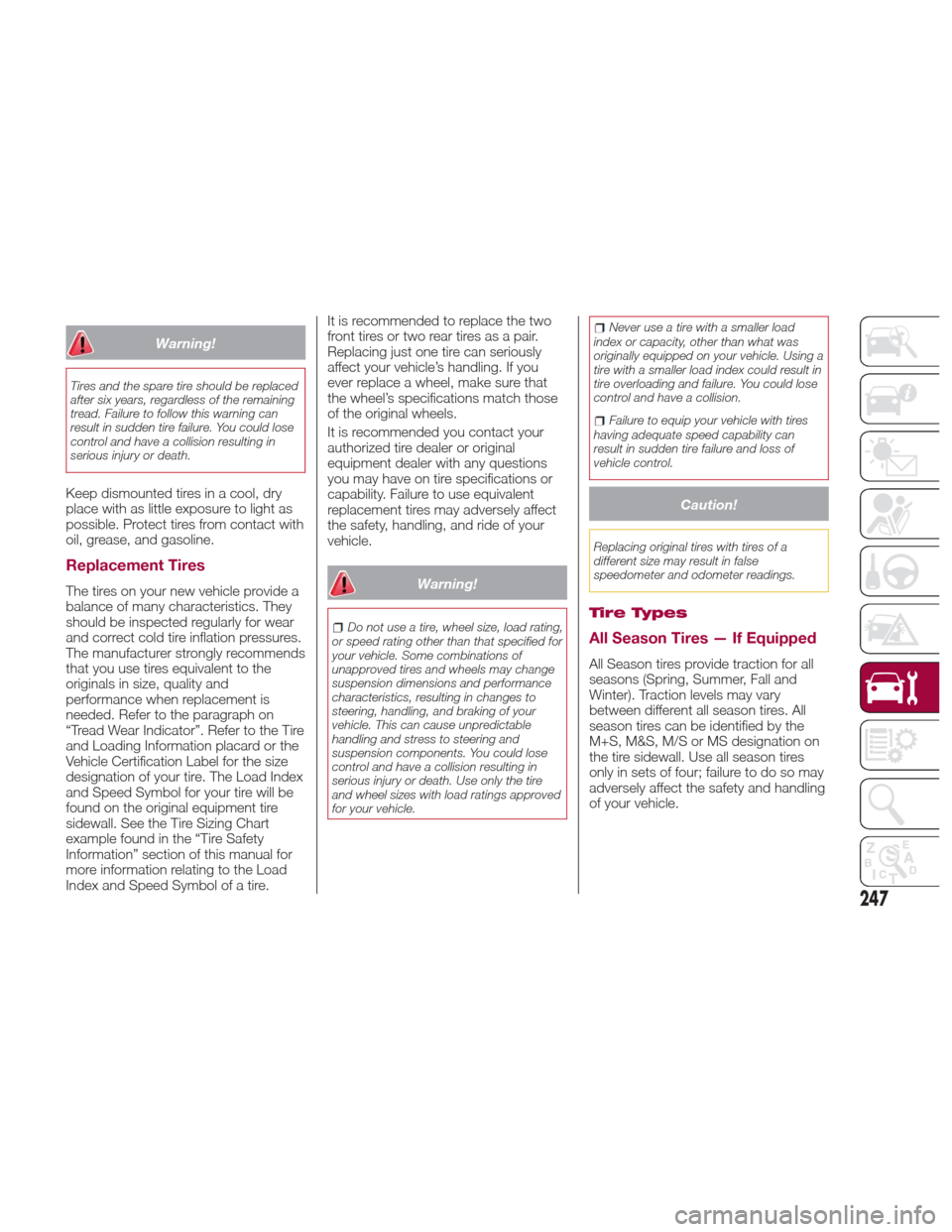
Warning!
Tires and the spare tire should be replaced
after six years, regardless of the remaining
tread. Failure to follow this warning can
result in sudden tire failure. You could lose
control and have a collision resulting in
serious injury or death.
Keep dismounted tires in a cool, dry
place with as little exposure to light as
possible. Protect tires from contact with
oil, grease, and gasoline.
Replacement Tires
The tires on your new vehicle provide a
balance of many characteristics. They
should be inspected regularly for wear
and correct cold tire inflation pressures.
The manufacturer strongly recommends
that you use tires equivalent to the
originals in size, quality and
performance when replacement is
needed. Refer to the paragraph on
“Tread Wear Indicator”. Refer to the Tire
and Loading Information placard or the
Vehicle Certification Label for the size
designation of your tire. The Load Index
and Speed Symbol for your tire will be
found on the original equipment tire
sidewall. See the Tire Sizing Chart
example found in the “Tire Safety
Information” section of this manual for
more information relating to the Load
Index and Speed Symbol of a tire.It is recommended to replace the two
front tires or two rear tires as a pair.
Replacing just one tire can seriously
affect your vehicle’s handling. If you
ever replace a wheel, make sure that
the wheel’s specifications match those
of the original wheels.
It is recommended you contact your
authorized tire dealer or original
equipment dealer with any questions
you may have on tire specifications or
capability. Failure to use equivalent
replacement tires may adversely affect
the safety, handling, and ride of your
vehicle.Warning!
Do not use a tire, wheel size, load rating,
or speed rating other than that specified for
your vehicle. Some combinations of
unapproved tires and wheels may change
suspension dimensions and performance
characteristics, resulting in changes to
steering, handling, and braking of your
vehicle. This can cause unpredictable
handling and stress to steering and
suspension components. You could lose
control and have a collision resulting in
serious injury or death. Use only the tire
and wheel sizes with load ratings approved
for your vehicle.
Never use a tire with a smaller load
index or capacity, other than what was
originally equipped on your vehicle. Using a
tire with a smaller load index could result in
tire overloading and failure. You could lose
control and have a collision.
Failure to equip your vehicle with tires
having adequate speed capability can
result in sudden tire failure and loss of
vehicle control.
Caution!
Replacing original tires with tires of a
different size may result in false
speedometer and odometer readings.
Tire Types
All Season Tires — If Equipped
All Season tires provide traction for all
seasons (Spring, Summer, Fall and
Winter). Traction levels may vary
between different all season tires. All
season tires can be identified by the
M+S, M&S, M/S or MS designation on
the tire sidewall. Use all season tires
only in sets of four; failure to do so may
adversely affect the safety and handling
of your vehicle.
247
Page 253 of 300
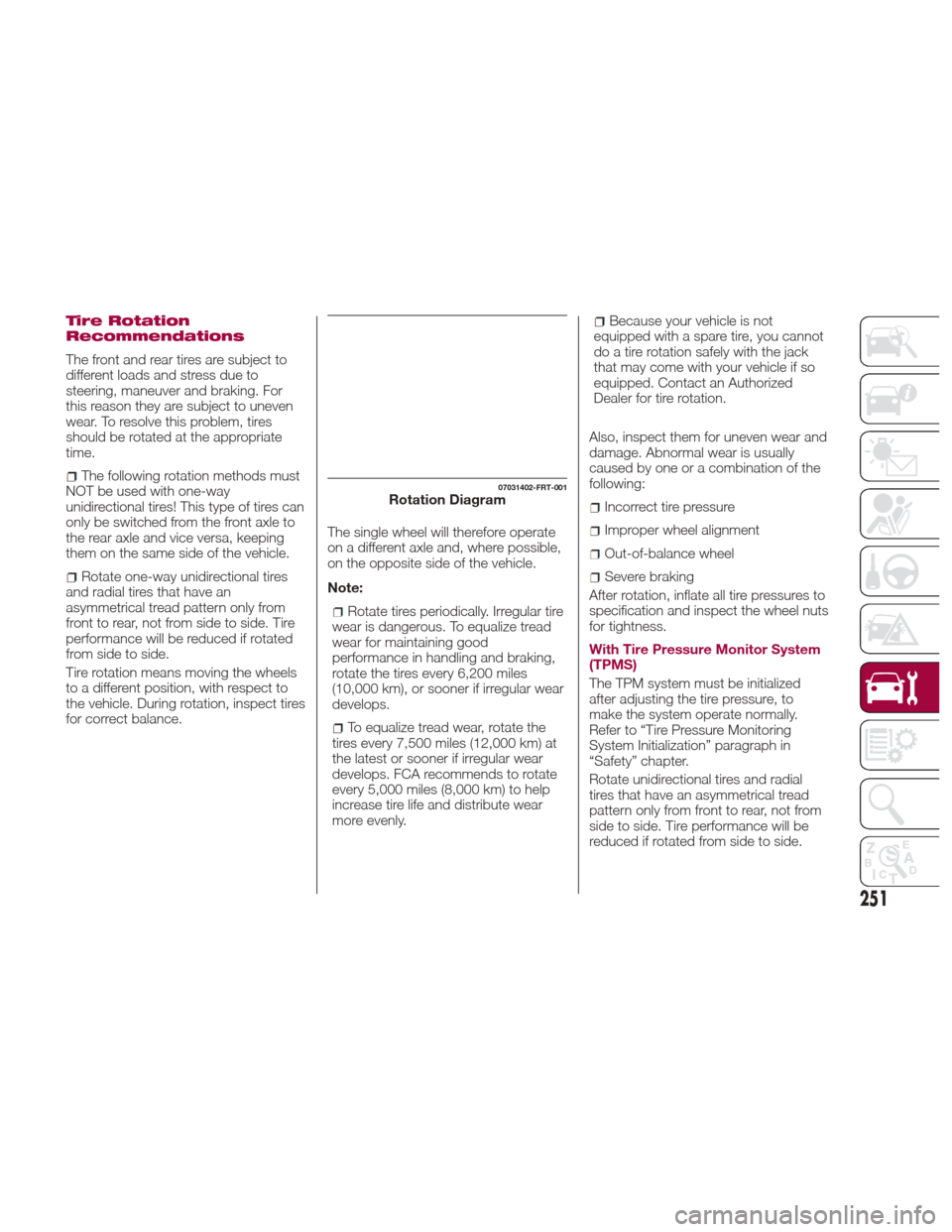
Tire Rotation
Recommendations
The front and rear tires are subject to
different loads and stress due to
steering, maneuver and braking. For
this reason they are subject to uneven
wear. To resolve this problem, tires
should be rotated at the appropriate
time.
The following rotation methods must
NOT be used with one-way
unidirectional tires! This type of tires can
only be switched from the front axle to
the rear axle and vice versa, keeping
them on the same side of the vehicle.
Rotate one-way unidirectional tires
and radial tires that have an
asymmetrical tread pattern only from
front to rear, not from side to side. Tire
performance will be reduced if rotated
from side to side.
Tire rotation means moving the wheels
to a different position, with respect to
the vehicle. During rotation, inspect tires
for correct balance. The single wheel will therefore operate
on a different axle and, where possible,
on the opposite side of the vehicle.
Note:
Rotate tires periodically. Irregular tire
wear is dangerous. To equalize tread
wear for maintaining good
performance in handling and braking,
rotate the tires every 6,200 miles
(10,000 km), or sooner if irregular wear
develops.
To equalize tread wear, rotate the
tires every 7,500 miles (12,000 km) at
the latest or sooner if irregular wear
develops. FCA recommends to rotate
every 5,000 miles (8,000 km) to help
increase tire life and distribute wear
more evenly.
Because your vehicle is not
equipped with a spare tire, you cannot
do a tire rotation safely with the jack
that may come with your vehicle if so
equipped. Contact an Authorized
Dealer for tire rotation.
Also, inspect them for uneven wear and
damage. Abnormal wear is usually
caused by one or a combination of the
following:
Incorrect tire pressure
Improper wheel alignment
Out-of-balance wheel
Severe braking
After rotation, inflate all tire pressures to
specification and inspect the wheel nuts
for tightness.
With Tire Pressure Monitor System
(TPMS)
The TPM system must be initialized
after adjusting the tire pressure, to
make the system operate normally.
Refer to “Tire Pressure Monitoring
System Initialization” paragraph in
“Safety” chapter.
Rotate unidirectional tires and radial
tires that have an asymmetrical tread
pattern only from front to rear, not from
side to side. Tire performance will be
reduced if rotated from side to side.
07031402-FRT-001Rotation Diagram
251
Page 288 of 300
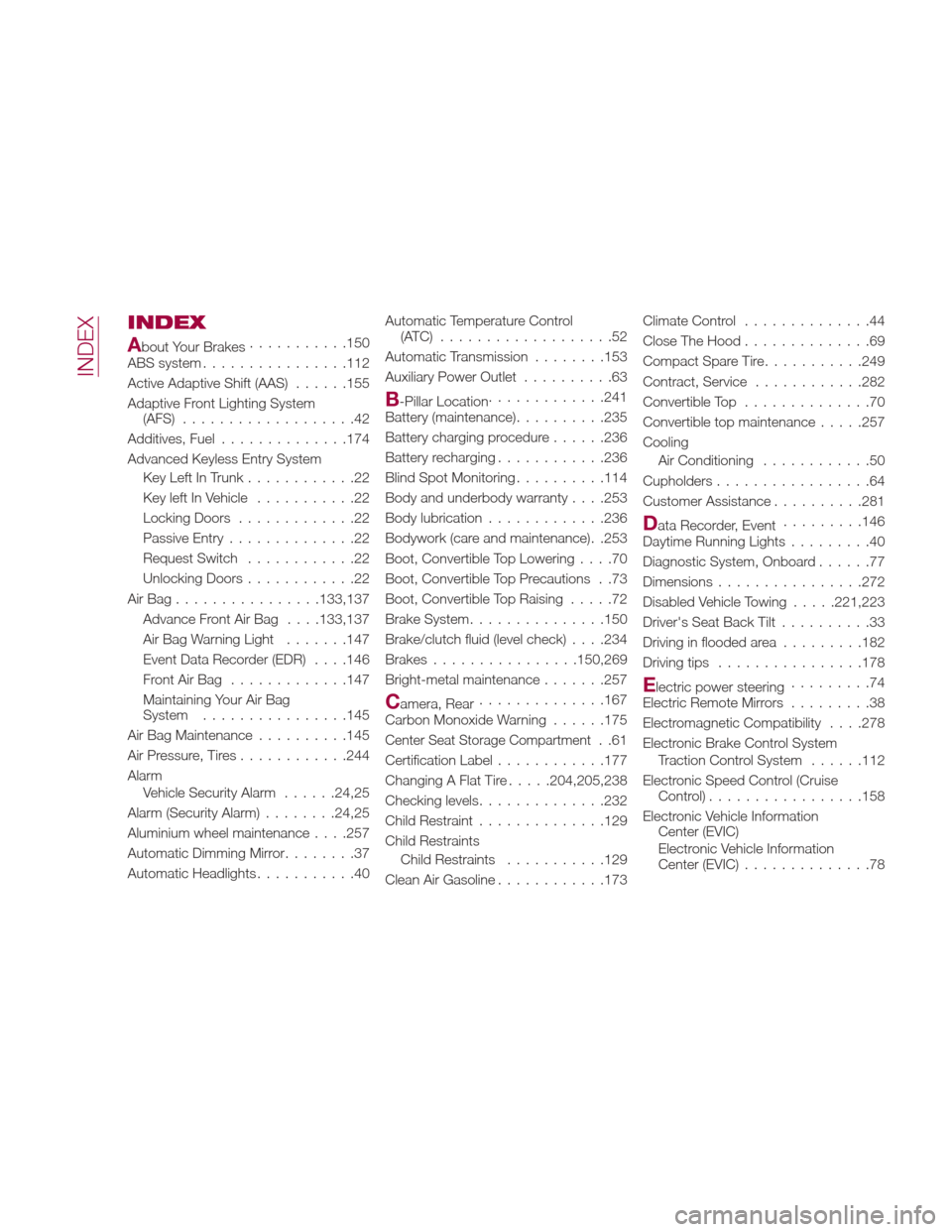
INDEX
About Your Brakes...........150
ABS system ............... .112
Active Adaptive Shift (AAS) ......155
Adaptive Front Lighting System (AFS) ...................42
Additives, Fuel ..............174
Advanced Keyless Entry System Key Left In Trunk ............22
Key left In Vehicle ...........22
Locking Doors .............22
Passive Entry ..............22
Request Switch ............22
Unlocking Doors ............22
AirBag............... .133,137
Advance Front Air Bag . . . .133,137
Air Bag Warning Light .......147
Event Data Recorder (EDR) . . . .146
FrontAirBag ............ .147
Maintaining Your Air Bag
System ............... .145
Air Bag Maintenance ..........145
Air Pressure, Tires ............244
Alarm Vehicle Security Alarm ......24,25
Alarm (Security Alarm) ........24,25
Aluminium wheel maintenance . . . .257
Automatic Dimming Mirror ........37
Automatic Headlights ...........40Automatic Temperature Control
(ATC) ...................52
Automatic Transmission ........153
Auxiliary Power Outlet ..........63
B-Pillar Location.............241
Battery (maintenance) ..........235
Battery charging procedure ......236
Battery recharging ............236
Blind Spot Monitoring ..........114
Body and underbody warranty . . . .253
Body lubrication .............236
Bodywork (care and maintenance). .253
Boot, Convertible Top Lowering ....70
Boot, Convertible Top Precautions . .73
Boot, Convertible Top Raising .....72
Brake System ...............150
Brake/clutch fluid (level check) . . . .234
Brakes ............... .150,269
Bright-metal maintenance .......257
Camera, Rear..............167
Carbon Monoxide Warning ......175
Center Seat Storage Compartment. .61
Certification Label ............177
Changing A Flat Tire .....204,205,238
Checking levels ..............232
Child Restraint ..............129
Child Restraints Child Restraints ...........129
Clean Air Gasoline ............173 Climate Control
..............44
Close The Hood ..............69
Compact Spare Tire ...........249
Contract, Service ............282
Convertible Top ..............70
Convertible top maintenance .....257
Cooling Air Conditioning ............50
Cupholders .................64
Customer Assistance ..........281
Data Recorder, Event.........146
Daytime Running Lights .........40
Diagnostic System, Onboard ......77
Dimensions ............... .272
Disabled Vehicle Towing .....221,223
Driver's Seat Back Tilt ..........33
Driving in flooded area .........182
Driving tips ............... .178
Electric power steering.........74
Electric Remote Mirrors .........38
Electromagnetic Compatibility . . . .278
Electronic Brake Control System Traction Control System ......112
Electronic Speed Control (Cruise Control) ................ .158
Electronic Vehicle Information Center (EVIC)
Electronic Vehicle Information
Center (EVIC) ..............78
INDEX
Page 291 of 300
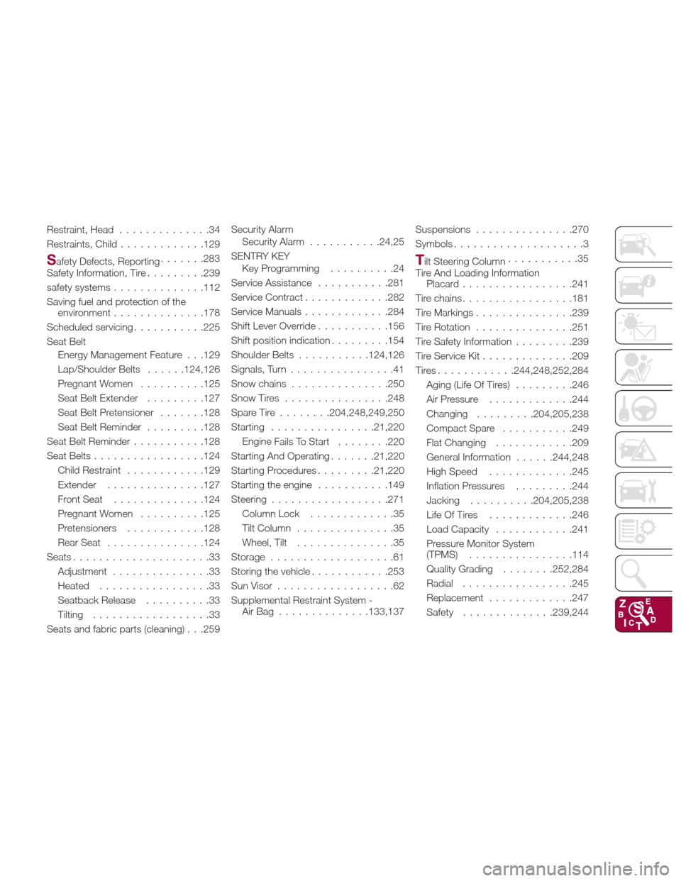
Restraint, Head..............34
Restraints, Child .............129
Safety Defects, Reporting .......283
Safety Information, Tire .........239
safety systems ..............112
Saving fuel and protection of the environment ..............178
Scheduled servicing ...........225
Seat Belt Energy Management Feature . . .129
Lap/Shoulder Belts ......124,126
Pregnant Women ..........125
Seat Belt Extender .........127
Seat Belt Pretensioner .......128
Seat Belt Reminder .........128
Seat Belt Reminder ...........128
Seat Belts ................ .124
Child Restraint ............129
Extender ...............127
Front Seat ..............124
Pregnant Women ..........125
Pretensioners ............128
Rear Seat ...............124
Seats .....................33
Adjustment ...............33
Heated .................33
Seatback Release ..........33
Tilting ..................33
Seats and fabric parts (cleaning) . . .259 Security Alarm
Security Alarm ...........24,25
SENTRY KEY Key Programming ..........24
Service Assistance ...........281
Service Contract .............282
Service Manuals .............284
Shift Lever Override ...........156
Shift position indication .........154
Shoulder Belts ...........124,126
Signals, Turn ................41
Snow chains ...............250
Snow Tires ............... .248
Spare Tire ........204,248,249,250
Starting ............... .21,220
Engine
Fails To Start ........220
Starting And Operating .......21,220
Starting Procedures .........21,220
Starting the engine ...........149
Steering ................. .271
Column Lock .............35
Tilt Column ...............35
Wheel, Tilt ...............35
Storage ...................61
Storing the vehicle ............253
Sun Visor ..................62
Supplemental Restraint System - AirBag ............. .133,137Suspensions
...............270
Symbols ....................3
Tilt Steering Column ...........35
Tire And Loading Information Placard ................ .241
Tire chains ................ .181
Tire Markings ...............239
Tire Rotation ...............251
Tire Safety Information .........239
Tire Service Kit ..............209
Tires............244,248,252,284 Aging (Life Of Tires) .........246
Air Pressure .............244
Changing .........204,205,238
Compact Spare ...........249
Flat Changing ............209
General Information ......244,248
High Speed .............245
Inflation Pressures .........244
Jacking ..........204,205,238
Life Of Tires .............246
Load Capacity ............241
Pressure Monitor System
(TPMS) ............... .114
Quality Grading ........252,284
Radial ................ .245
Replacement .............247
Safety ..............239,244