Top FIAT 500 1959 1.G User Guide
[x] Cancel search | Manufacturer: FIAT, Model Year: 1959, Model line: 500, Model: FIAT 500 1959 1.GPages: 128, PDF Size: 9.01 MB
Page 24 of 128
sections of the air conveyor securing with seven
screws, seven toothed washers and five nuts.
22 Slide the fuel pump control rod into its seating,
assemble the insulator between oil wetted graphite
gaskets and fit the pump to the crankcase using nuts
and toothed washers.
23 Fit the air conveyor cover complete with the accelera-
tor control relay lever and rod. Secure using eight
mounting screws, eight toothed washers, eight plain
washers and eight nuts. Fit the fuel line retaining clip
which is secured by one of the air conveyor upper
screws. Install the generator and fan drive pulley
having first placed four adjusting rings between the
pulley halves and the thrust ring on the outside.
Secure the pulley to generator shaft using three
screws and three toothed washers. Fit the generator
fan drive belt.
24 Refit the carburetter having first positioned the
bakelite heat shield between the t w o oil moistened
graphite gaskets. Secure the carburetter using t w o
copper washers and t w o self-locking nuts. Fit the
exhaust silencer and secure to the exhaust manifolds
with nuts and spring washers. Place the t w o graphite
gaskets between the manifold joints. Fit both exhaust
silencer upper mounting brackets and secure them
on the top side to the brackets already in place w i t h
nuts and toothed washers on the bottom side w i t h
screws and toothed washers.
25 Carefully position the distributor at a 10 deg advance
setting and secure w i t h a
nut, plain washer and
spring washer. Fit the fuel pump to carburetter line
complete w i t h mounting bracket rubber lining and
secure the line with two clamps. If difficulty is
experienced in positioning the fuel line into the pump
or carburetter funnels it is suggested that the line
ends should be heated in hot water and thoroughly
dried before installing.
26 Install the air cleaner elbow and rubber hose assembly
on the top of the carburetter using a graphite gasket
in between and secure w i t h nuts, plain washers and
spring washers. Carefully position the air cleaner, line
and hose assembly and connect it to the elbow.
Secure the cleaner to air conveyor cover using screws
and toothed washers.
27 Fit the spark plug cables complete with the rubber
grommet for cable mounting bracket on engine
cowling and connect the cables to the distributor
and spark plugs. Fit the oil pressure gauge sender
unit together w i t h its sealing washer.
28 Install the cylinder head cover and oil breather pipe
assembly w i t h a cork gasket inserted between.
Secure w i t h self-locking nuts and fibre washers.
Connect the accelerator control relay lever rod to the
carburetter and secure with the clip.
29 Fill the oil pan with the correct grade and quantity of
oil, insert the dipstick and the engine is ready for
refitting.
1:18 Engine assembly (station wagon)
Reassembly of this engine is straightforward as it is
the reverse procedure to dismantling. It is recommended
that Sections 1 :5 and 1 :17 are studied as the assembly
technique is similar for both the horizontal and vertical
F50031 cylinder engines. The following points should however
be noted:
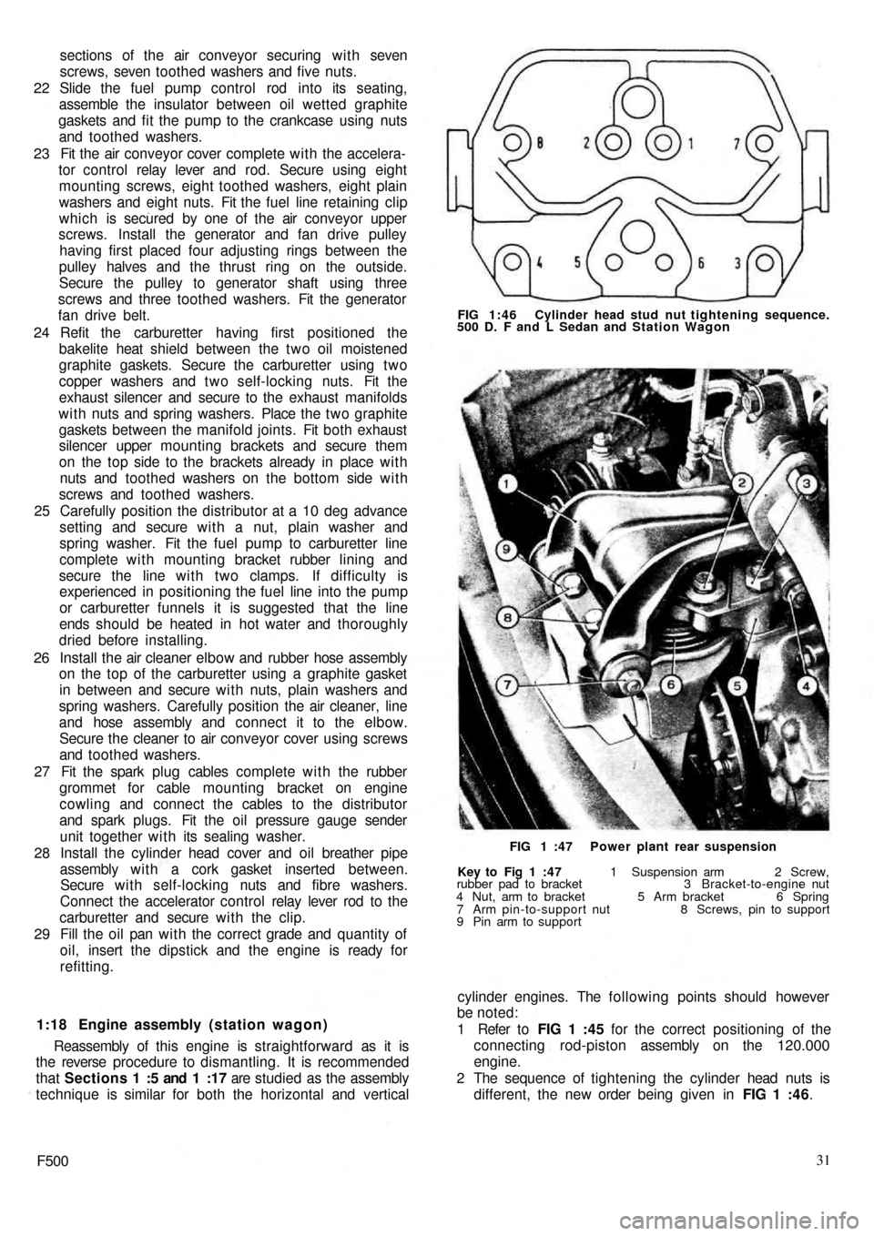
1 Refer to FIG 1 :45 for the correct positioning of the
connecting rod-piston assembly on the 120.000
engine.
2 The sequence of tightening the cylinder head nuts is
different, the new order being given in FIG 1 :46.
Key to Fig 1 :47 1 Suspension arm 2 Screw,
rubber pad to bracket 3 Bracket-to-engine nut
4 Nut, arm to bracket 5 Arm bracket 6 Spring
7 Arm pin-to-support nut 8 Screws, pin to support
9 Pin arm to supportFIG 1 :47 Power plant rear suspension FIG 1:46 Cylinder head stud nut tightening sequence.
500 D. F and L Sedan and Station Wagon
Page 28 of 128
CHAPTER 2
THE FUEL SYSTEM
2:1 Description
2 : 2 Fuel pump operating principles
2 : 3 Routine maintenance
2 : 4 Pump removal, dismantling and examination
2 : 5 Reassembly, installation and adjustment
2 : 6 Carburetter operation and adjustment,
Weber 26.1MB2 : 7 Modifications
2 : 8 Carburetter operation and adjustment,
Weber 26.OC
2 :9 Air cleaner
2 : 1 0 B l o w - b y gases recirculation device
2:11 Fuel tank
2:12 Fault diagnosis
2:1 Description
All the new 500 models use a mechanical diaphragm
fuel feed pump as shown in FIG 2 : 1. Four types of
carburetter are fitted depending on the model to which
the engine is installed. Each carburetter operation and
adjustment is fully described, together with details of the
recirculation device for blow-by gases and o i l vapours.
2 : 2 Fuel pump operating principles
Refer to FIG 2 : 2. An eccentric on the rotating camshaft
actuates the operating rocker 21 via a pushrod 25 which
depresses the diaphragm 14 and so creates a depression
in the pumping chamber located in upper body 5. Under
atmospheric pressure, petrol passes through the pipeline
connection and inlet valve into the pumping chamber.
The return spring 15 then raises the diaphragm, expelling
the petrol through the outlet valve and pipeline to the
carburetter float chamber.
When the float chamber is full, the pressure in the pipe-
line and pumping chamber holds the diaphragm depressed
against the tension of the return spring.2 : 3 Routine maintenance
A poor delivery of fuel to the carburetter may be due to
a fault in the fuel pump or related lines. Periodically the
pump body screws 19 (see FIG 2 : 2) and upper cover
screw 1 should be checked for tightness. The fuel pump
lines should be disconnected and checked for freedom of
restriction, chafing and loose connections. The fuel pump
filter should be removed and cleaned periodically.
2:4 Pump removal, dismantling and examination
The pump is located on the carburetter side of the
engine crankcase (sedan) or under the generator at the
front of the crankcase (station wagon).
Removal:
1 Disconnect the fuel pipe from the tank to stop petrol
syphoning out of the tank and then release the fuel
inlet and outlet pipes from the pump body.
2 Remove the t w o nuts and washers holding pump to
crankcase.
3 Carefully lift away the pump, gaskets and insulating pad
from the crankcase (see FIG 2 : 3).
F50035
Page 32 of 128
3 Engine warm-up:
As the engine begins to warm up to its normal operating
temperature, gradually push home the starting device
lever so as only to supply the engine with the richened
charge enabling the cold engine operation to be smooth
and regular. Position ' B ' (FIG 2:6).
4 Normal car driving:
Once the engine has reached its normal operating
temperature the starting device should be completely
brought out of operation by bringing the control lever to
the position 'C (FIG 2:6).
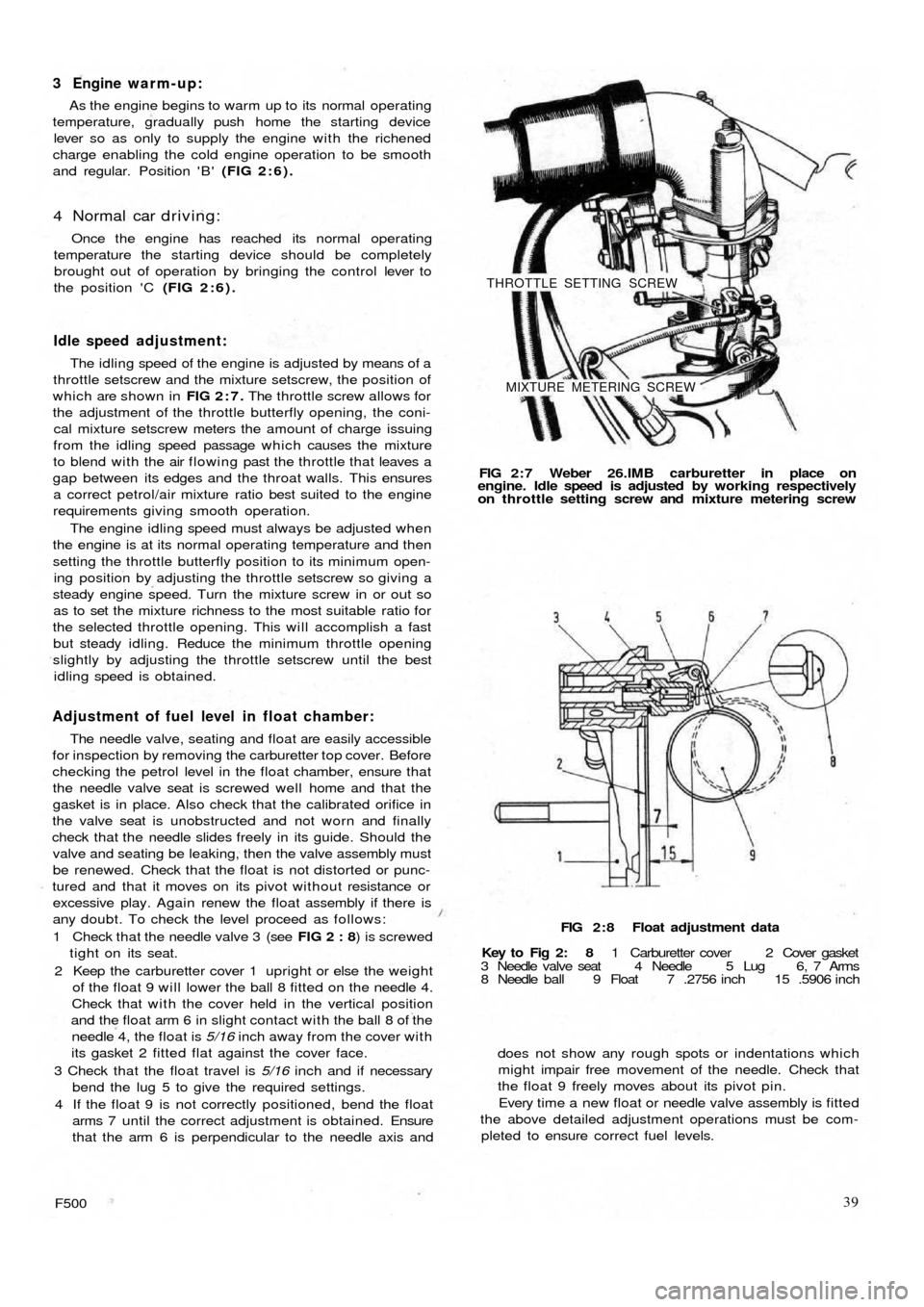
Idle speed adjustment:
The idling speed of the engine is adjusted by means of a
throttle setscrew and the mixture setscrew, the position of
which are shown in FIG 2:7. The throttle screw allows for
the adjustment of the throttle butterfly opening, the coni-
cal mixture setscrew meters the amount of charge issuing
from the idling speed passage which causes the mixture
to blend with the air flowing past the throttle that leaves a
gap between its edges and the throat walls. This ensures
a correct petrol/air mixture ratio best suited to the engine
requirements giving smooth operation.
The engine idling speed must always be adjusted when
the engine is at its normal operating temperature and then
setting the throttle butterfly position to its minimum open-
ing position by adjusting the throttle setscrew so giving a
steady engine speed. Turn the mixture screw in or out so
as to set the mixture richness to the most suitable ratio for
the selected throttle opening. This will accomplish a fast
but steady idling. Reduce the minimum throttle opening
slightly by adjusting the throttle setscrew until the best
idling speed is obtained.
Adjustment of fuel level in float chamber:
The needle valve, seating and float are easily accessible
for inspection by removing the carburetter top cover. Before
checking the petrol level in the float chamber, ensure that
the needle valve seat is screwed well home and that the
gasket is in place. Also check that the calibrated orifice in
the valve seat is unobstructed and not worn and finally
check that the needle slides freely in its guide. Should the
valve and seating be leaking, then the valve assembly must
be renewed. Check that the float is not distorted or punc-
tured and that it moves on its pivot without resistance or
excessive play. Again renew the float assembly if there is
any doubt. To check the level proceed as follows:
1 Check that the needle valve 3 (see FIG 2 : 8) is screwed
tight on its seat.
2 Keep the carburetter cover 1 upright or else the weight
of the float 9 will lower the ball 8 fitted on the needle 4.
Check that with the cover held in the vertical position
and the float arm 6 in slight contact with the ball 8 of the
needle 4, the float is 5/16 inch away from the cover with
its gasket 2
fitted flat against the cover face.
3 Check that the float travel is 5/16 inch and if necessary
bend the lug 5 to give the required settings.
4 If the float 9 is not correctly positioned, bend the float
arms 7 until the correct adjustment is obtained. Ensure
that the arm 6 is perpendicular to the needle axis and
F50039
does not show any rough spots or indentations which
might impair free movement of the needle. Check that
the float 9 freely moves about its pivot pin.
Every time a new float or needle valve assembly is fitted
the above detailed adjustment operations must be com-
pleted to ensure correct fuel levels. FIG 2 : 8 Float adjustment data
Key to Fig 2: 8 1 Carburetter cover 2 Cover gasket
3 Needle valve seat 4 Needle 5 Lug 6, 7 Arms
8 Needle ball 9 Float 7 .2756 inch 15 .5906 inch FIG 2 : 7 Weber 26.IMB carburetter in place on
engine. Idle speed is adjusted by working respectively
on throttle setting screw and mixture metering screw
THROTTLE SETTING SCREW
MIXTURE METERING SCREW
Page 33 of 128
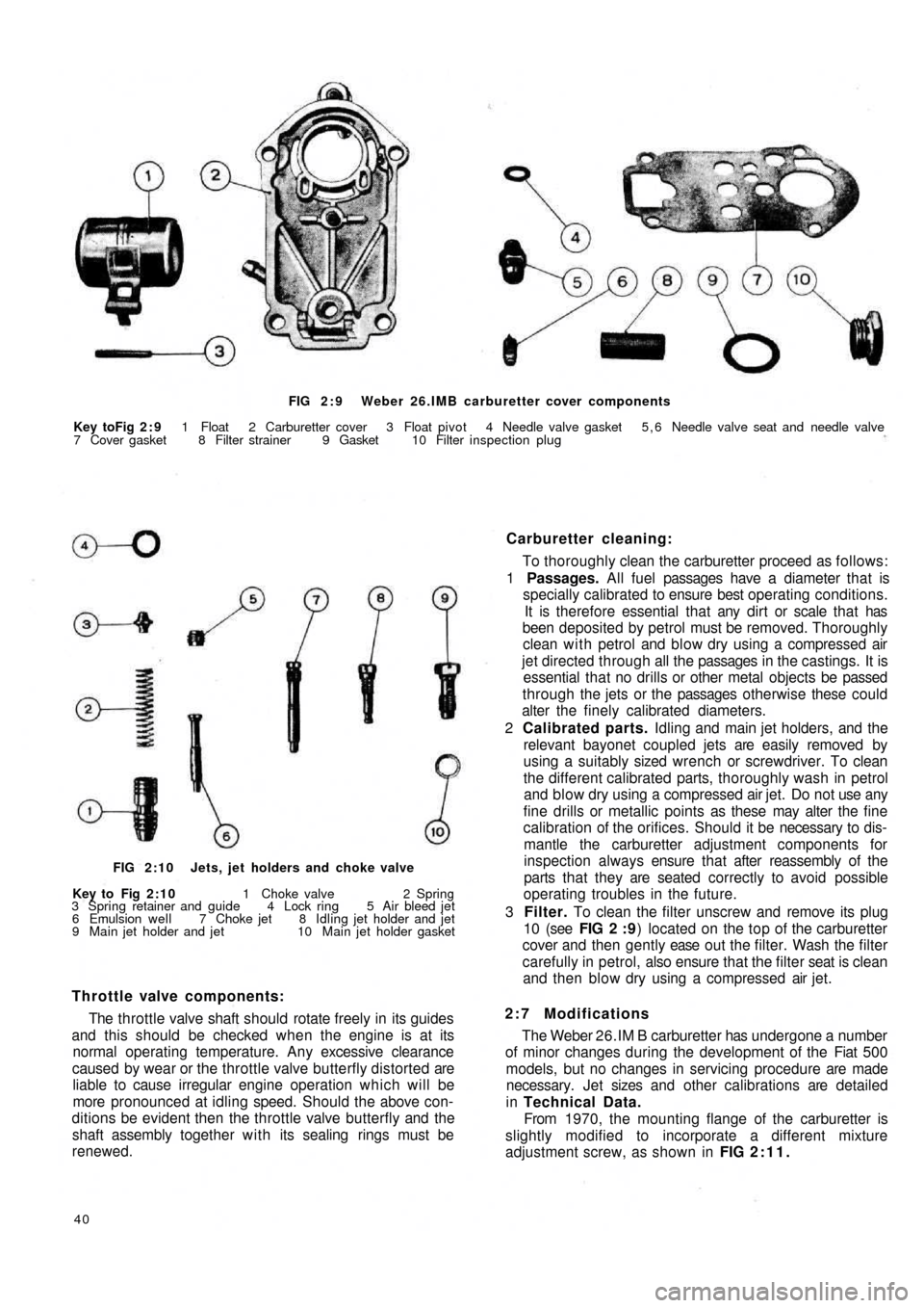
FIG 2 : 9 Weber 26.IMB carburetter cover components
Key toFig 2 : 9 1 Float 2 Carburetter cover 3 Float pivot 4 Needle valve gasket 5 , 6 Needle valve seat and needle valve
7 Cover gasket 8 Filter strainer 9 Gasket 10 Filter inspection plug
Carburetter cleaning:
To thoroughly clean the carburetter proceed as follows:
1 Passages. All fuel passages have a diameter that is
specially calibrated to ensure best operating conditions.
It is therefore essential that any dirt or scale that has
been deposited by petrol must be removed. Thoroughly
clean with petrol and blow dry using a compressed air
jet directed through all the passages in the castings. It is
essential that no drills or other metal objects be passed
through the jets or the passages otherwise these could
alter the finely calibrated diameters.
2 Calibrated parts. Idling and main jet holders, and the
relevant bayonet coupled jets are easily removed by
using a suitably sized wrench or screwdriver. To clean
the different calibrated parts, thoroughly wash in petrol
and blow dry using a compressed air jet. Do not use any
fine drills or metallic points as these may alter the fine
calibration of the orifices. Should it be necessary to dis-
mantle the carburetter adjustment components for
inspection always ensure that after reassembly of the
parts that they are seated correctly to avoid possible
operating troubles in the future.
3 Filter. To clean the filter unscrew and remove its plug
10 (see FIG 2 : 9) located on the top of the carburetter
cover and then gently ease o u t t h e filter. Wash the filter
carefully in petrol, also ensure that the filter seat is clean
and then blow dry using a compressed air jet.
2:7 Modifications
The Weber 26.IM B carburetter has undergone a number
of minor changes during the development of the Fiat 500
models, but no changes in servicing procedure are made
necessary. Jet sizes and other calibrations are detailed
in Technical Data.
From 1970, the mounting flange of the carburetter is
slightly modified to incorporate a different mixture
adjustment screw, as shown in FIG 2:11.
40
Throttle valve components:
The throttle valve shaft should rotate freely in its guides
and this should be checked when the engine is at its
normal operating temperature. Any excessive clearance
caused by wear or the throttle valve butterfly distorted are
liable to cause irregular engine operation which will be
more pronounced at idling speed. Should the above con-
ditions be evident then the throttle valve butterfly and the
shaft assembly together with its sealing rings must be
renewed.
FIG 2:10 Jets, jet holders and choke valve
Key to Fig 2:10 1 Choke valve 2 Spring
3 Spring retainer and guide 4 Lock ring 5 Air bleed jet
6 Emulsion well 7 Choke jet 8 Idling jet holder and jet
9 Main jet holder and jet 10 Main jet holder gasket
Page 40 of 128
3:1
3:2
3:3
3:4
3:5Description
Operation
Routine maintenance
Ignition faults
Removing and dismantling distributor (sedan
and sports)
CHAPTER 3
THE IGNITION SYSTEM
3:6
3:7
3:8
3:9
3:10
Removing and dismantling
(station wagon)
Timing the ignition
Sparking plugs
The distributor drive spindle
Fault diagnosisdistributor
3 :1 Description
The ignition system fitted to all the models covered by
this manual consists of an ignition coil, ignition distributor
fitted with contact breaker points, a centrifugal automatic
advance system, condenser, low- and high-tension
wiring, spark plugs and a power supply provided by a
generator and battery. The wiring diagram is shown in
FIG 3 : 1
1 The low-tension circuit which is sometimes called the
primary circuit includes the power supply, contact
breaker points, condenser and ignition coil primary
winding.
2 The high-tension circuit which is sometimes called the
secondary circuit includes the ignition coil secondary
winding, distributor rotor, distributor cap with terminals
and the central brush, high-tension cables and the spark
plugs.
3 : 2 Operation
The contact breaker unit in the distributor interrupts
the primary circuit by the points opening. The sudden stop
in the flow of current in the primary winding, does not cause
arcing at the contact breaker points because it discharges
into the condenser connected in parallel w i t h the contact
F50047
breaker points. With the sudden collapse of the primary
circuit, the intensity of the magnetic field drops causing
an induced high-tension current in the ignition coil
secondary winding. The high EMF is distributed to the
sparking plugs by the ignition distributor rotor.
The automatic advance mechanism comprises a plate
carrying t w o weights which are symmetrically pivoted on
the plate at one end. Also attached to the weights at
opposite ends to the pivots is the cam carrier shaft with
special tension return springs. Under the action of centri-
fugal force as the rotational speed increases, the weights
move outwards causing the cam carrier shaft to move
angularly compared to the distributor drive shaft thus
causing advancement of the ignition timing.
The contact breaker assembly comprises the cam on the
drive shaft and t w o contact points, one of which is
stationary while the other is under the influence of the
cam, the action of which is transmitted by a rubbing block.
The cam has t w o lobes to control the opening and closing
of contact points. The stationary contact point is mounted
on an adjustable support to enable the contact breaker
point gap to be adjusted.
The HT current reaches the distributor cap central
terminal, from the ignition coil and is distributed to each
of the spark plugs at the correct time by the rotor arm.
Page 41 of 128
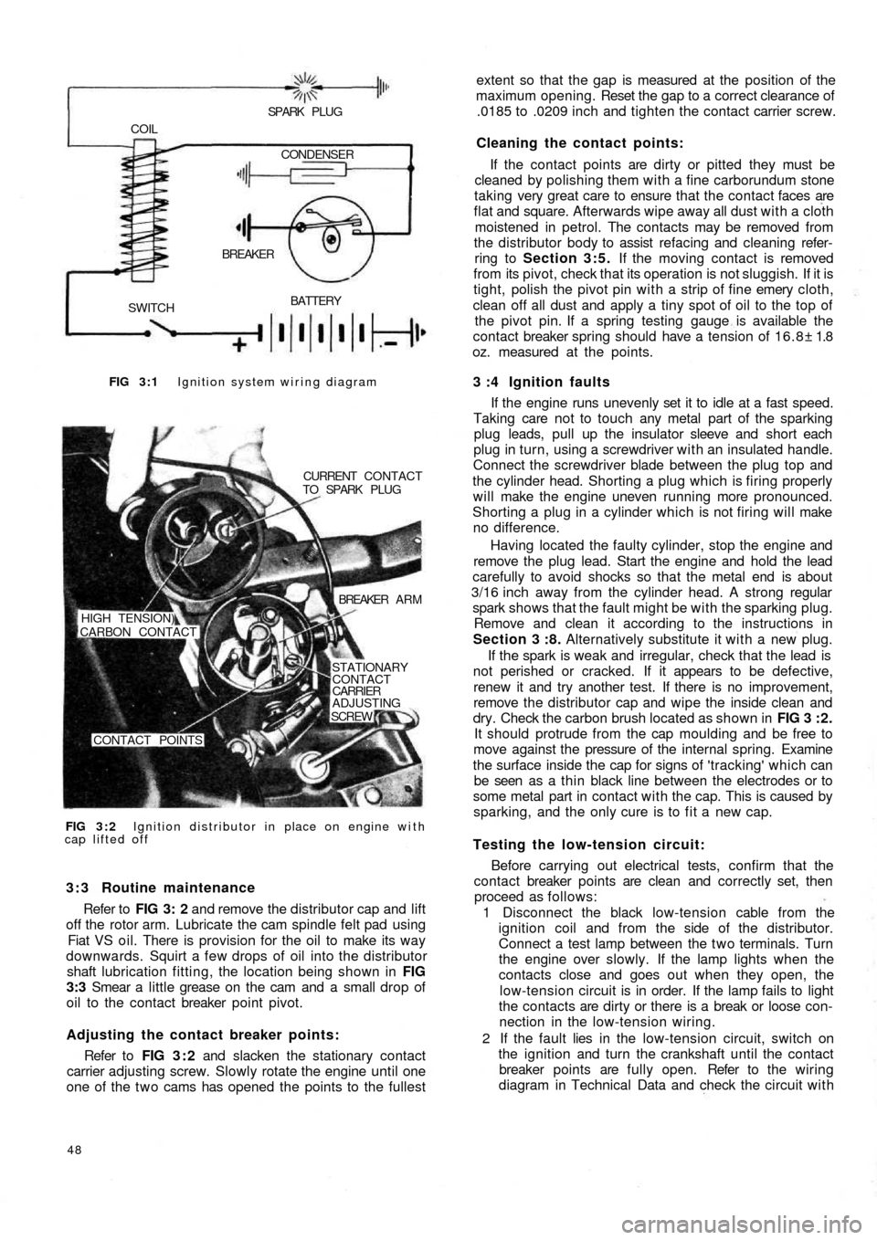
FIG 3 : 1 Ignition system wiring diagram
BATTERY
SWITCHBREAKER COIL
SPARK PLUG
CONDENSER
FIG 3 : 2 Ignition distributor in place on engine with
cap lifted offCURRENT CONTACT
TO SPARK PLUG
BREAKER A R M
STATIONARY
CONTACT
CARRIER
ADJUSTING
SCREW
CONTACT POINTS HIGH TENSION)
CARBON CONTACT
3 : 3 Routine maintenance
Refer to FIG 3: 2 and remove the distributor cap and lift
off the rotor arm. Lubricate the cam spindle felt pad using
Fiat VS oil. There is provision for the oil to make its way
downwards. Squirt a few drops of oil into the distributor
shaft lubrication fitting, the location being shown in FIG
3:3 Smear a little grease on the cam and a small drop of
oil to the contact breaker point pivot.
Adjusting the contact breaker points:
Refer to FIG 3 : 2 and slacken the stationary contact
carrier adjusting screw. Slowly rotate the engine until one
one of the t w o cams has opened the points to the fullest
48
extent so that the gap is measured at the position of the
maximum opening. Reset the gap to a correct clearance of
.0185 to .0209 inch and tighten the contact carrier screw.
Cleaning the contact points:
If the contact points are dirty or pitted they must be
cleaned by polishing them with a fine carborundum stone
taking very great care to ensure that the contact faces are
flat and square. Afterwards wipe away all dust with a cloth
moistened in petrol. The contacts may be removed from
the distributor body to assist refacing and cleaning refer-
ring to Section 3:5. If the moving contact is removed
from its pivot, check that its operation is not sluggish. If it is
tight, polish the pivot pin with a strip of fine emery cloth,
clean off all dust and apply a tiny spot of oil to the top of
the pivot pin. If a spring testing gauge is available the
contact breaker spring should have a tension of 16.8± 1.8
oz. measured at the points.
3 :4 Ignition faults
If the engine runs unevenly set it to idle at a fast speed.
Taking care not to touch any metal part of the sparking
plug leads, pull up the insulator sleeve and short each
plug in turn, using a screwdriver with an insulated handle.
Connect the screwdriver blade between the plug top and
the cylinder head. Shorting a plug which is firing properly
will make the engine uneven running more pronounced.
Shorting a plug in a cylinder which is not firing will make
no difference.
Having located the
faulty cylinder, stop the engine and
remove the plug lead. Start the engine and hold the lead
carefully to avoid shocks so that the metal end is about
3/16 inch away from the cylinder head. A strong regular
spark shows that the fault might be with the sparking plug.
Remove and clean it according to the instructions in
Section 3 :8. Alternatively substitute it with a new plug.
If the spark is weak and irregular, check that the lead is
not perished or cracked. If it appears to be defective,
renew it and try another test. If there is no improvement,
remove the distributor cap and wipe the inside clean and
dry. Check the carbon brush located as shown in FIG 3 : 2 .
It should protrude from the cap moulding and be free to
move against the pressure of the internal spring. Examine
the surface inside the cap for signs of 'tracking' which can
be seen as a thin black line between the electrodes or to
some metal part in contact with the cap. This is caused by
sparking, and the only cure is to fit a new cap.
Testing the low-tension circuit:
Before carrying out electrical tests, confirm that the
contact breaker points are clean and correctly set, then
proceed as follows:
1 Disconnect the black low-tension cable from the
ignition coil and from the side of the distributor.
Connect a test lamp between the t w o terminals. Turn
the engine over slowly. If the lamp lights when the
contacts close and goes out when they open, the
low-tension circuit is in order. If the lamp fails to light
the contacts are dirty or there is a break or loose con-
nection in the low-tension wiring.
2 If the fault lies in the
low-tension circuit, switch on
the ignition and turn the crankshaft until the contact
breaker points are fully open. Refer to the wiring
diagram in Technical Data and check the circuit with
Page 42 of 128
a n 0—20 v o ltmeter. If the circuit is in order the meter
should read approximately 12-volts.
3 Battery to fuse box terminal 30. Connect the volt-
meter between the terminal 30 and earth. No reading
indicates a faulty cable or loose connection.
4 Fuse box. Connect the voltmeter between the other
auxiliary terminal 30 and earth. No reading indicates a
broken or loose connection.
5 Fuse box auxiliary terminal 30 to terminal
number 30 on ignition switch. Connect the meter
between terminal number 30 on the ignition switch
and earth. No reading indicates a damaged cable or
loose connection.
6 Ignition switch. Connect the meter between termi-
nal 15/54 and earth. Switch onto the ignition position,
when no reading indicates a fault in the switch.
7 Ignition switch to low-tension cable connection
on the coil (blue cable). Connect the meter
between ignition coil terminal (blue cable) and earth.
No reading indicates a damaged cable or loose con-
nection.
8 Ignition coil. Disconnect the black low-tension cable
connecting the coil to the distributor side terminal at
the coil and connect the meter between this terminal
and earth. No reading indicates a fault in the primary
winding of the coil and a replacement coil must be
fitted. If the reading is correct remake the connections
to the coil.
9 Ignition coil to distributor. Disconnect the thin
black low-tension cable at the side of the distributor
and connect the meter between the end of this cable
and earth. No reading indicates a damaged cable or
loose connections.
10 Contact breaker and capacitor. Connect the
meter across the contact breaker points. No reading
indicates a faulty capacitor.
Capacitor:
The best method of testing a capacitor (condenser) is
by substitution. Disconnect the original capacitor and
connect a new one between the low-tension terminal on
the side of the distributor and earth.
If a new capacitor is needed, fit a new one complete
w i t h bracket, but if necessary unsolder the original bracket
and solder it onto the new capacitor using as little heat as
possible. Capacitor capacity is .15-.20 microfarads.
3 : 5 Removing and dismantling distributor (sedan
and sports)
To remove the distributor proceed as follows:
1 Rotate the engine slowly until the distributor rotor arm
is opposite the brass segment in the distributor cap
connected to No. 1 plug lead. This will provide a datum
for replacement.
2 Disconnect the cable from the low-tension terminal on
the side of the distributor body. Mark position of distri-
butor on support. Release the distributor retaining nut
and washer from the underside of the top flange of the
distributor support and carefully lift away the dis-
tributor.
3 Pull off the rotor arm. Remove the insulated terminal
assembly from the side of distributor body. Release the
contact breaker carrier plate retaining screws and con-
denser flange screw from the outside of the distributor
F50049 body. Carefully lift out the contact breaker plate
assembly.
4 Before further dismantling note the relative positions of
the driving dog and the rotor arm driving slot at the top
of the distributor cam spindle. The driving dog is offset
and can only engage its driving spindle in one position.
Then when the cam assembly is fitted to the centrifugal
weights during reassembly the timing is not 180 deg.
out.
5 Take out the cam lubrication felt pad recessed in the
rotor arm housing on the end of the cam spindle.
Remove the retaining screw, carefully disengage the
springs and lift out the cam spindle. It should be noted
that there is a small retaining ball and spring located in a
drilling nearly at the top of the drive shaft spindle.
Carefully lift away the weights.
6 Thoroughly clean all parts and inspect for excessive
wear. The distributor cap must not be cracked or show
signs of tracking. The cap terminals, rotor and contact
breaker points can be cleaned with a very fine file.
Emerypaper must not be used. If the clearance between
the rotor and distributor cap segments exceeds .0118
inch both the rotor and distributor cap must be replaced.
Inspect the contact breaker arm rubbing block for exces-
sive wear and also the points for wear so that if the gap
exceeds the last setting limit of .0209 inch and adjust-
ment through the stationary contact carrier screw is no
longer possible (see FIG 3 : 2) , the contact breaker set
must be renewed.
If the distributor drive shaft side or vertical movement is
excessive the distributor must be renewed.
Weak centri-
fugal weight springs or damaged weights must be
renewed using original Fiat spares otherwise the auto-
matic ignition advance characteristics could be altered.
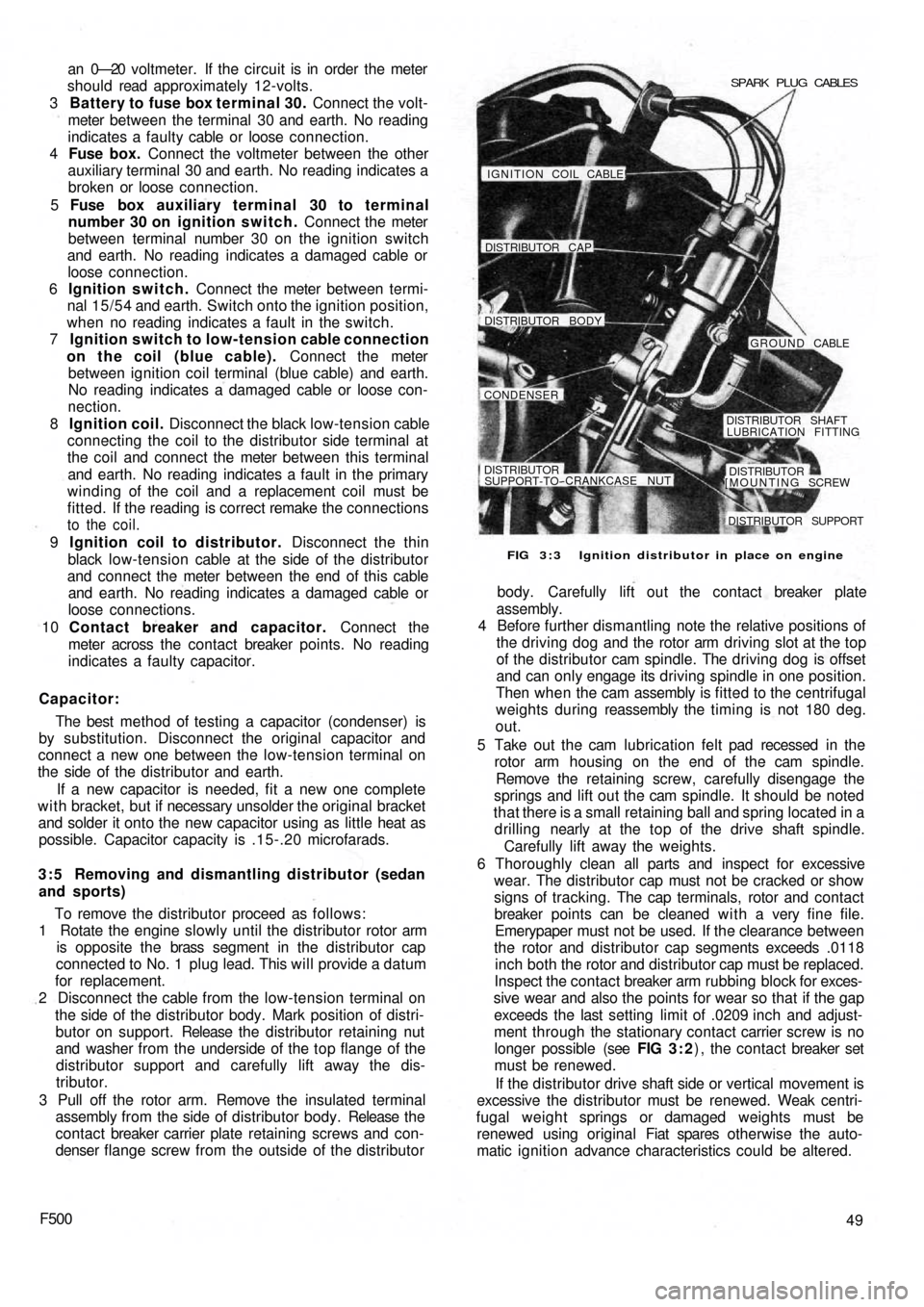
FIG 3 : 3 Ignition distributor in place on engine SPARK PLUG CABLES
IGNITION COIL CABLE!
DISTRIBUTOR CAP
DISTRIBUTOR BODY
GROUND CABLE
CONDENSER
DISTRIBUTOR SHAFT
LUBRICATION FITTING
DISTRIBUTORSUPPORT-TO--CRANKCASE NUT
[MOUNTING SCREWDISTRIBUTOR
DISTRIBUTOR SUPPORT
Page 43 of 128
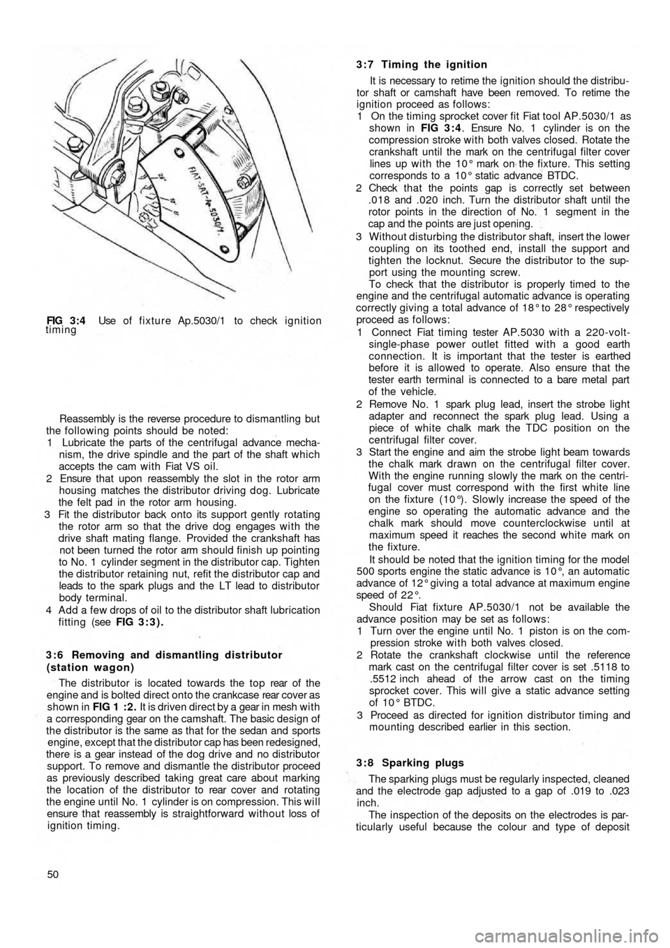
FIG 3 : 4 Use of fixture Ap.5030/1 to check ignition
timing
Reassembly is the reverse procedure to dismantling but
the following points should be noted:
1 Lubricate the parts of the centrifugal advance mecha-
nism, the drive spindle and the part of the shaft which
accepts the cam w i t h Fiat VS oil.
2 Ensure that upon reassembly the slot in the rotor arm
housing matches the distributor driving dog. Lubricate
the felt pad in the rotor arm housing.
3 Fit the distributor back onto its support gently rotating
the rotor arm so that the drive dog engages w i t h the
drive shaft mating flange. Provided the crankshaft has
not been turned the rotor arm should finish up pointing
to No. 1 cylinder segment in the distributor cap. Tighten
the distributor retaining nut, refit the distributor cap and
leads to the spark plugs and the LT lead to distributor
body terminal.
4 Add a few drops of oil to the distributor shaft lubrication
fitting (see FIG 3:3).
3 : 6 Removing and dismantling distributor
(station wagon)
The distributor is located towards the top rear of t h e
engine and is bolted direct onto the crankcase rear cover as
shown in FIG 1 : 2 . It is driven direct by a gear in mesh w i t h
a corresponding gear on the camshaft. The basic design of
the distributor is the same as that for the sedan and sports
engine, except that the distributor cap has been redesigned,
there is a gear instead of the dog
drive and no distributor
support. To remove and dismantle the distributor proceed
as previously described taking great care about marking
the location of the distributor to rear cover and rotating
the engine until No. 1 cylinder is on compression. This will
ensure that reassembly is straightforward without loss of
ignition timing.
503:7 Timing the ignition
It is necessary to retime the ignition should the distribu-
tor shaft or camshaft have been removed. To retime the
ignition proceed as follows:
1 On the timing sprocket cover fit Fiat tool AP.5030/1 as
shown in FIG 3 : 4. Ensure No. 1 cylinder is on the
compression stroke with both valves closed. Rotate the
crankshaft until the mark on the centrifugal filter cover
lines up w i t h the 10° mark on the fixture. This setting
corresponds to a 10° static advance BTDC.
2 Check t h a t the points gap is correctly set between
.018 and .020 inch. Turn the distributor shaft until the
rotor points in the direction of No. 1 segment in the
cap and the points are just opening.
3 Without disturbing the distributor shaft, insert the lower
coupling on its toothed end, install the support and
tighten the locknut. Secure the distributor to the sup-
port using the mounting screw.
To check that the distributor is properly timed to the
engine and the centrifugal automatic advance is operating
correctly giving a
total advance of 18° to 28° respectively
proceed as follows:
1 Connect Fiat timing tester AP.5030 with a 220-volt-
single-phase power outlet fitted with a good earth
connection. It is important that the tester is earthed
before it is allowed to operate. Also ensure that the
tester earth terminal is connected to a bare metal part
of the vehicle.
2 Remove No. 1 spark plug lead, insert the strobe light
adapter and reconnect the spark plug lead. Using a
piece of white chalk mark the TDC position on the
centrifugal filter cover.
3 Start the engine and aim the strobe light beam towards
the chalk mark drawn on the centrifugal filter cover.
With the engine running slowly the mark on the centri-
fugal cover must correspond wi th the first white line
on the fixture (10°). Slowly increase the speed of the
engine so operating the automatic advance and the
chalk mark should move counterclockwise until at
maximum speed it reaches the second white mark on
the fixture.
It should be noted that the ignition timing for the model
500 sports engine the static advance is 10°, an automatic
advance of 12° giving a total advance at maximum engine
speed of 2 2 ° .
Should Fiat fixture AP.5030/1 not be available the
advance position may be set as follows:
1 Turn over the
engine until No. 1 piston is on the com-
pression stroke w i t h both valves closed.
2 Rotate the crankshaft clockwise until the reference
mark cast on the centrifugal filter cover is set .5118 to
.5512 inch ahead of the arrow cast on the timing
sprocket cover. This will give a static advance setting
of 10° BTDC.
3 Proceed as directed for ignition distributor timing and
mounting described earlier in this section.
3 : 8 Sparking plugs
The sparking plugs must be regularly inspected, cleaned
and the electrode gap adjusted to a gap of .019 to .023
inch.
The inspection of the deposits on the electrodes is par-
ticularly useful because the colour and type of deposit
Page 44 of 128
indicates the condition inside the combustion chamber
and may be used as a guide to engine tuning.
Before the spark plugs are removed b l o w away any
loose dirt from the plug recesses using a compressed air
jet or tyre pump. Store the plugs in the order of removal
ready for inspection.
Examine the gaskets and if they are about half their
thickness they may be used again otherwise they must be
replaced.
Inspect the electrode end of the plugs and note the
type and colour of the deposit. Normally it should be
powdery and range from b r o w n to a greyish tan in colour.
There will also be slight wear of the electrodes and the
general effect described is one which comes from mixed
periods of high-speed and low-speed driving. Cleaning
and resetting the gap is all that will be necessary.
If the deposits are white or yellowish they indicate long
periods of constant-speed driving or much low-speed
city driving. Again, the treatment is straightforward.
Dry, black, fluffy deposits are usually the result of
running with too rich a mixture. Incomplete combustion
of the petrol air charge may also be a cause and this might
be traced to a defect in the ignition system or excessive
idling.
Overheated sparking plugs have a white blistered look
about the centre electrode and the side electrode may be
badly eroded. This may be caused by poor cooling, wrong
ignition timing or sustained high speeds under heavy load.
To clean the sparking plugs effectively they should be
cleaned using an abrasive blasting machine and tested
under pressure once the electrodes have been reset. File
these until they are clean, bright and the faces parallel and
set the gap to .019 to .023 inch. Do not try to bend the
centre electrode.
Before replacing the plugs use a wire brush to clean the
threads taking care that the electrodes are not touched.
Thoroughly clean the spark plug in petrol, and dry using a
compressed air jet or a tyre pump. If difficulty is found in
screwing the plugs into the cylinder head by hand run a
tap d o w n the threads to clear away any carbon. If a tap is
not available use an old sparking plug with crosscuts d o w nthe threads. Finally tighten the plugs to a torque wrench
setting of 18 to 21 Ib ft.
Sparking plug leads:
The spark plug leads and the lead from the coil to the
distributor cap must be regularly checked for cracking of
the insulation and also correct seating in the distributor
cap and coil top. It is recommended that silicone grease is
smeared around the sockets before the leads are replaced
to ensure no moisture may enter causing difficult starting.
3 : 9 The distributor driving spindle (sedan and
sports engine)
If for any reason, the driving spindle has been removed
from its housing in the crankcase, it must be correctly
meshed w i t h the camshaft gear otherwise it
will be impos-
sible to set the ignition timing.
3:10 Fault diagnosis
(a) Engine w i l l not fire
1 Battery discharged
2 Distributor contact points dirty, pitted or maladjusted
3 Distributor cap dirty, cracked or tracking
4 Carbon brush inside distributor cap not touching rotor
5 Faulty cable or loose connection in low-tension circuit
6 Distributor rotor arm cracked
7 Faulty coil
8 Broken contact breaker spring
9 Contact points stuck open
(b) Engine misfires
1 Check 2, 3, 4, and 7 in (a)
2 Weak contact breaker spring
3 High-tension plug and coil leads cracked or perished
4 Sparking plug(s) loose
5 Sparking plug insulation cracked
6 Sparking plug gap incorrectly set
7 Ignition timing too far advanced
Page 56 of 128
lubricated using Fiat Jota 3 grease.
1 Pressure plate—boss outer faces.
2 Clutch cover—withdrawal lever fulcrum.
3 Withdrawal lever stopnuts—contact face.
4 Withdrawal lever carrier ring — lever contact face.
5 Crankcase end pilot bushing lubricated with Fiat KG.15
grease.
6 Lubricate contact faces of driven plate and clutch shaft.
To install the clutch assembly proceed as follows:
1 Ensure t h a t there is no grease or oil on the faces of the
driven plate or flywheel face and position with the
raised part of the hub towards the transmission unit.
2 Locate Fiat tool A.70085 (diaphragm clutch) or
A . 6 2 0 2 3 (coil spring clutch) or a suitably sized drift,
through the driven plate hub and position in crankshaft
pilot bushing. Gradually tighten the clutch unit
mounting screws working diagonally and finally tighten
to a torque wrench setting of 5.8 to 7.2 Ib ft.
5 : 6 Pilot bushing
Whenever the clutch unit is being renewed or over-
hauled it is essential that the crankshaft pilot bush is
checked for excessive wear or damage. Also check that
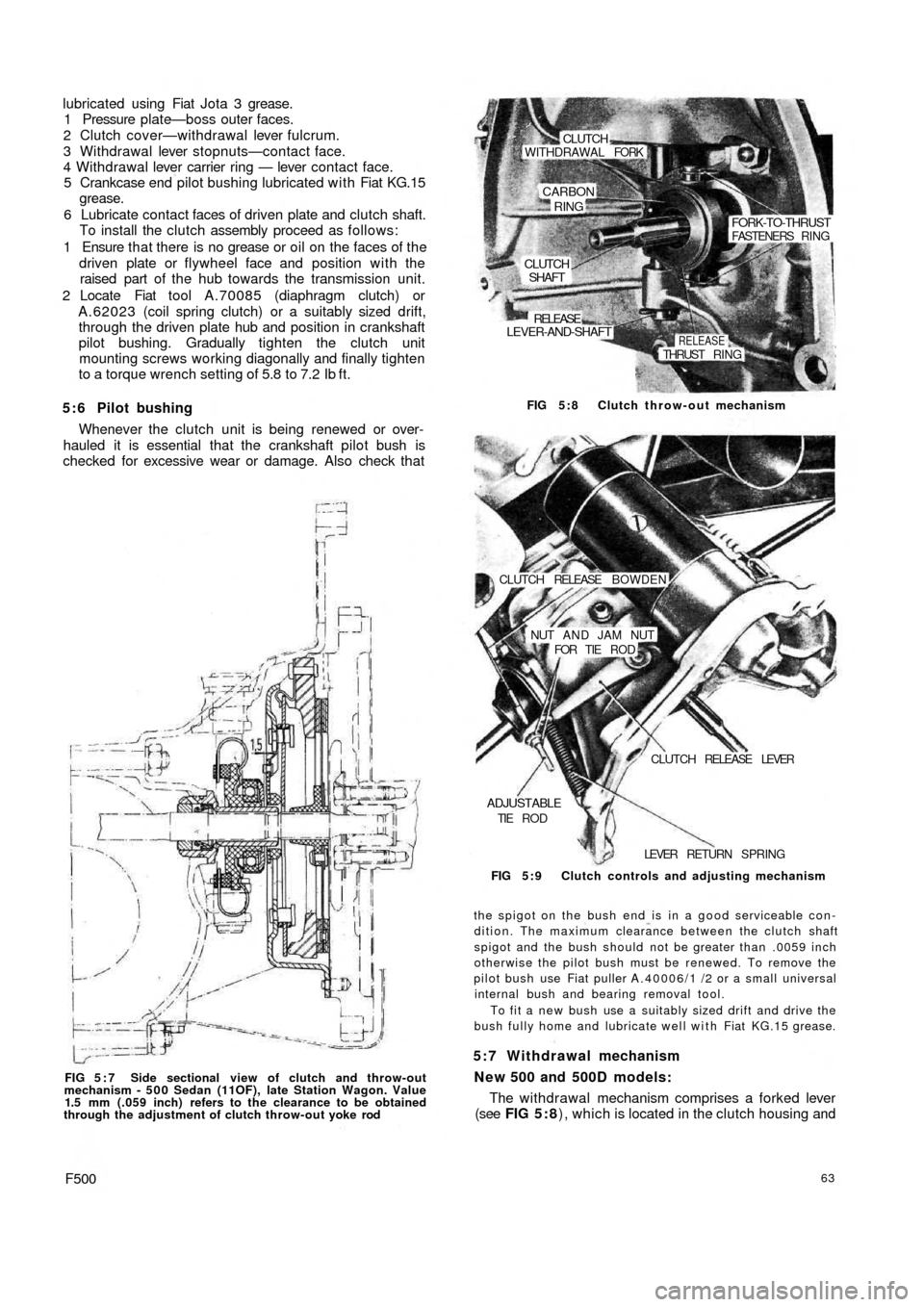
FIG 5 : 7 Side sectional view of clutch and throw-out
mechanism - 5 0 0 Sedan (11OF), late Station Wagon. Value
1.5 mm (.059 inch) refers to the clearance to be obtained
through the adjustment of clutch throw-out yoke rod
F50063
The withdrawal mechanism comprises a forked lever
(see FIG 5 : 8), which is located in the clutch housing and 5:7 Withdrawal mechanism
New 500 and 500D models:
the spigot on the bush end is in a good serviceable con-
dition. The maximum clearance between the clutch shaft
spigot and the bush should not be greater than .0059 inch
otherwise the pilot bush must be renewed. To remove the
pilot bush use Fiat puller A.40006/1 /2 or a small universal
internal bush and bearing removal tool.
To fit a new bush use a suitably sized drift and drive the
bush fully home and lubricate well with Fiat KG.15 grease. FIG 5 : 9 Clutch controls and adjusting mechanism LEVER RETURN SPRING
ADJUSTABLETIE R O DCLUTCH RELEASE LEVER NUT A N D JAM NUT
FOR TIE R O D CLUTCH RELEASE BOWDEN FIG 5:8 Clutch throw-out mechanism
CLUTCHSHAFT
LEVER-AND-SHAFT
RELEASE
RELEASETHRUST RING
FORK-TO-THRUSTFASTENERS RING
CARBON
RING
WITHDRAWAL FORKCLUTCH