Top FIAT 500 1959 1.G Service Manual
[x] Cancel search | Manufacturer: FIAT, Model Year: 1959, Model line: 500, Model: FIAT 500 1959 1.GPages: 128, PDF Size: 9.01 MB
Page 123 of 128
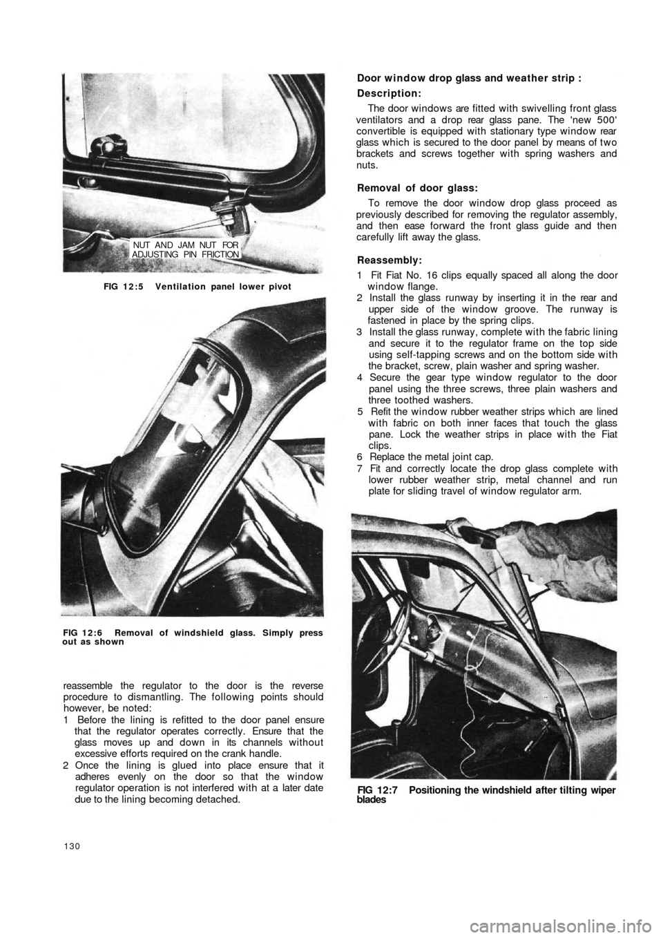
NUT AND JAM NUT FOR
ADJUSTING PIN FRICTION
FIG 12:5 Ventilation panel lower pivot
FIG 12:6 Removal of windshield glass. Simply press
out as shown
reassemble the regulator to the door is the reverse
procedure to dismantling. The following points should
however, be noted:
1 Before the lining is refitted to the door panel ensure
that the regulator operates correctly. Ensure t h a t the
glass moves up and down in its channels without
excessive efforts required on the crank handle.
2 Once the lining is glued into place ensure that it
adheres evenly on the door so that the window
regulator operation is not interfered with at a later date
due to the lining becoming detached.
130
FIG 12:7 Positioning the windshield after tilting wiperblades
Door window drop glass and weather strip :
Description:
The door windows are fitted with swivelling front glass
ventilators and a drop rear glass pane. The 'new 500'
convertible is equipped with stationary type window rear
glass which is secured to the door panel by means of t w o
brackets and screws together with spring washers and
nuts.
Removal of door glass:
To remove the door window drop glass proceed as
previously described for removing the regulator assembly,
and t h e n ease forward the front glass guide and then
carefully lift away the glass.
Reassembly:
1 Fit Fiat No. 16 clips equally spaced all along the door
window flange.
2 Install the glass runway by inserting it in the rear and
upper side of the window groove. The runway is
fastened in place by the spring clips.
3 Install the glass runway, complete with the fabric lining
and secure it to the regulator frame on the top side
using self-tapping screws and on the bottom side w i t h
the bracket, screw, plain washer and spring washer.
4 Secure the gear type window regulator to the door
panel using the three screws, three plain washers and
three toothed washers.
5 Refit the window rubber weather strips which are lined
with fabric on both inner faces that touch the glass
pane. Lock the weather strips in place w i t h the Fiat
clips.
6 Replace the metal joint cap.
7 Fit and correctly locate the drop glass complete with
lower rubber weather strip, metal channel and run
plate for sliding travel of window regulator arm.
Page 125 of 128
SEAT RUBBER PAD
SEAT ARTICULATION SUPPORT
SEAT MECHANISM
CONTROL LEVER
SEAT SLIDING GUIDE
SEAT FIXED GUIDE
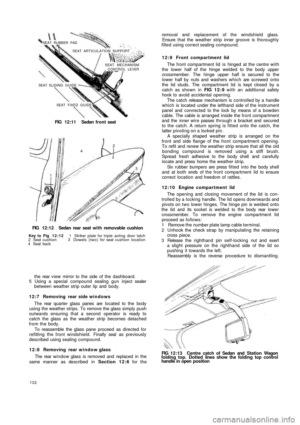
FIG 12:11 Sedan front seat
42
3
1
FIG 12:12 Sedan rear seat w i t h removable cushion
Key to Fig 12:12 1 Striker plate for triple acting door latch
2 Seat cushion 3 Dowels (two) for seat cushion location
4 Seat back
t h e rear v i e w mirror to the side of the dashboard.
5 Using a special compound sealing gun inject sealer
between weather strip outer lip and body.
12:7 Removing rear side windows
The rear quarter glass panes are located to the body
using the weather strips. To remove the glass simply push
outwards ensuring that a second operator is ready to
catch the glass as the weather strip becomes detached
from the body.
To reassemble the glass pane proceed as directed for
refitting the front windshield. Finally seal as previously
described using sealing compound.
12:8 Removing rear window glass
The rear window glass is removed and replaced in the
same manner as described in Section 12:6 for the
132
FIG 12:13 Centre catch of Sedan and Station Wagon
folding top. Dotted lines show the folding top control
handle in open position removal and replacement of the windshield glass.
Ensure t h a t the weather strip inner groove is thoroughly
filled using correct sealing compound.
1 2 : 9 Front compartment lid
The front compartment lid is hinged at the centre w i t h
the lower half of the hinge welded to the body upper
crossmember. The hinge upper half is secured to the
lower half by nuts and washers which are screwed onto
the lid studs. The compartment lid is kept closed by a
catch as shown in FIG 1 2 : 9 with an additional safety
hook to avoid accidental opening.
The catch release mechanism is controlled by a handle
which is located under the lefthand side of the instrument
panel and connected to the lock by means of a bowden
cable. The cable is arranged inside the front compartment
and the inner wire passes through a bracket and secured
to the catch. A return spring is fitted onto the catch, the
latter pivoting on a locked pin.
A specially shaped weather strip is arranged on the
front and side flange of the front compartment opening.
To refit and renew the weather strip ensure that all the old
bonding compound is removed using a stiff brush.
Spread fresh adhesive to the body shell and carefully
locate and press home the weather strip.
Six rubber bumpers are press fitted into the body shell
and at both ends of the front compartment lid to ensure
correct location and freedom of rattles.
12:10 Engine compartment lid
The opening and closing movement of the lid is con-
trolled by a locking handle. The lid opens downwards and
pivots on two lower hinges. The hinge pin is welded onto
the lid and its socket is welded to the body rear lower
crossmember. To remove the engine compartment lid
proceed as follows:
1 Remove the number plate lamp cable terminal.
2 Unhook the check strap by manipulating the retaining
cross piece.
3 Release the righthand pin self-locking nut and exert
a slight pressure on the righthand side of the lid so
pushing it towards the left.
Reassembly is the reverse procedure to dismantling.
Page 126 of 128
12:11 Folding top
The f ol di n g top assembly comprises the following
items:
1 Imitation leather top w i t h vinylite back window.
2 Front end frame complete with two handles and
catches. A movable bow which slides on the frame
guide rails.
3 Three stiffening bows fixed by chrome plated buttons
and tipped with rubber blocks.
4 Front mouldings for t o p mounting on frame.
5 Rear moulding on top mounting engine cooling air
intake body panel.
6 Retaining strap for the roller stop.
The removal of the folding top is straightforward but
care should be taken on reassembly to the vehicle and the
following points should be noted:
1 The t o p rear moulding is secured by ten screws
consisting of six self-tapping screws and four standard
screws which are located as follows:
(a) One long self-tapping screw at each end.
(b) Two standard screws at centre.
(c) Two standard screws next to the long screws.
(d) Four self-tapping screws, two on each side
between the standard screws.
These screws also secure the upper end of the engine
air intake panel to body.
2 Having fixed the rear moulding spread the top across
t h e o p e n i n g . Ensure t h e pivoting bow is located
between the second and third stiffening bows. Using
special screws fix the frame rails to the upper inner
ends of the body side panels.
12:12 Sunroof
The 'new 500' sunroof model differs from the con-
vertible model in the arrangement of the top. The sunroof
comprises a rear metal panel and a front imitation leather
covering which acts as a collapsible top.
The weather strip surrounded back window is
located
on t h e rear metal panel and the following items are
cemented in place; plastic lining, foam rubber strip at
upper front end, and two rubber welts located on the
sides to prevent water ingress.
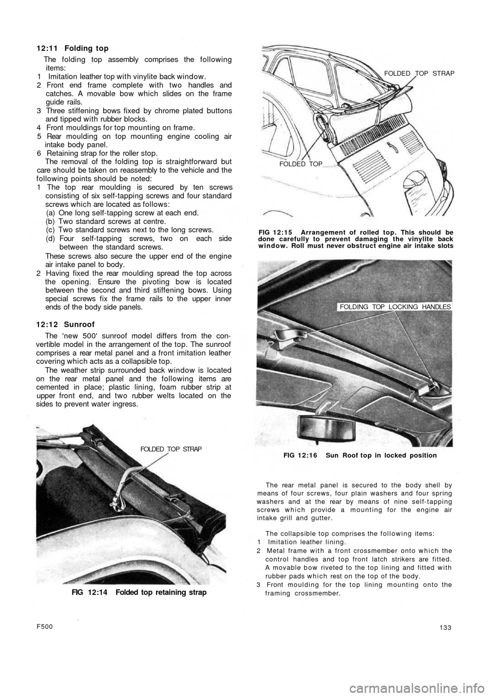
FIG 12:14 Folded top retaining strap
F500
133 FOLDED TOP STRAP
FOLDED TOP
FIG 12:15 Arrangement of rolled top. This should be
done carefully to prevent damaging the vinylite back
window. Roll must never obstruct engine air intake slots
FOLDING TOP LOCKING HANDLES
FIG 12:16 Sun Roof top in locked position
The rear metal panel is secured to the body shell by
means of four screws, four plain washers and four spring
washers and at the rear by means of nine self-tapping
screws which provide a mounting for the engine air
intake grill and gutter.
The collapsible top comprises the following items:
1 Imitation leather lining.
2 Metal frame with a front crossmember onto which the
control handles and top front latch strikers are fitted.
A movable bow riveted to the top lining and fitted with
rubber pads which rest on t h e t o p of t h e body.
3 Front moulding for the top lining mounting onto the
framing crossmember. FOLDED TOP STRAP
Page 127 of 128
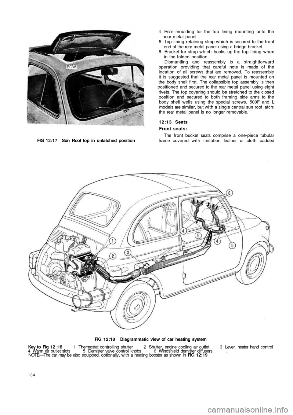
BOW
FIG 12:17 Sun Roof top in unlatched position
FIG 12:18 Diagrammatic view of car heating system
Key to Fig 12 :18 1 Thermostat controlling shutter 2 Shutter, engine cooling air outlet 3 Lever, heater hand control
4 Warm air outlet slots 5 Demister valve control knobs 6 Windshield demister diffusers
NOTE—The car may be also equipped, optionally, with a heating booster as shown in FIG 12:19
134
4 Rear moulding for the top lining mounting onto the
rear metal panel.
5 Top lining retaining strap which is secured to the front
end of t h e rear metal panel using a bridge bracket.
6 Bracket for strap which hooks up the top lining when
in the folded position.
Dismantling and reassembly is a straightforward
operation providing that careful note is made of the
location of all screws that are removed. To reassemble
it is suggested that the rear metal panel is mounted on
the body shell first. The collapsible top assembly is then
positioned and secured to the rear metal panel using eight
rivets. The top covering should be stretched to the closed
position and secured to both framing side arms to t h e
body shell wells using the special screws. 500F and L
models are similar, but with a single central sun roof latch:
t h e rear metal panel is no longer removable.
12:13 Seats
Front seats:
The front bucket seats comprise a one-piece tubular
frame covered with imitation leather or cloth padded