brake FIAT 500 1971 1.G User Guide
[x] Cancel search | Manufacturer: FIAT, Model Year: 1971, Model line: 500, Model: FIAT 500 1971 1.GPages: 128, PDF Size: 9.01 MB
Page 87 of 128
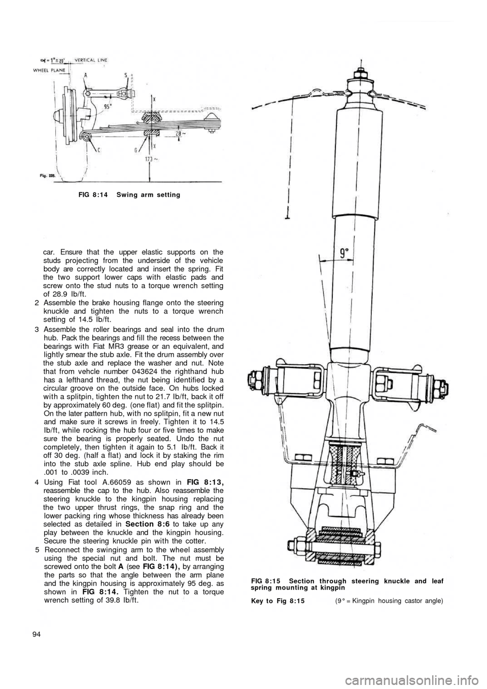
FIG 8:14 Swing arm setting
car. Ensure t h a t the upper elastic supports on the
studs projecting from the underside of the vehicle
body are correctly located and insert the spring. Fit
the two support lower caps w i t h elastic pads and
screw onto the stud nuts to a torque wrench setting
of 28.9 Ib/ft.
2 Assemble the brake housing flange onto the steering
knuckle and tighten the nuts to a torque wrench
setting of 14.5 Ib/ft.
3 Assemble the roller bearings and seal into the drum
hub. Pack the bearings and fill the recess between the
bearings w i t h Fiat MR3 grease or an equivalent, and
lightly smear the stub axle. Fit the drum assembly over
the stub axle and replace the washer and nut. Note
that from vehcle number 043624 the righthand hub
has a lefthand thread, the nut being identified by a
circular groove on the outside face. On hubs locked
with a splitpin, tighten the nut to 21.7 Ib/ft, back it off
by approximately 60 deg. (one flat) and fit the splitpin.
On the later pattern hub, with no splitpin, fit a new nut
and make sure it screws in freely. Tighten it to 14.5
Ib/ft, while rocking the hub four or five times to make
sure the bearing is properly seated. Undo the nut
completely, then tighten it again to 5.1 Ib/ft. Back it
off 30 deg. (half a flat) and lock it by staking the rim
into the stub axle spline. Hub end play should be
.001 to .0039 inch.
4 Using Fiat tool A.66059 as shown in FIG 8:13,
reassemble the cap to the hub. Also reassemble the
steering knuckle to the kingpin housing replacing
the t w o upper
thrust rings, the snap ring and the
lower packing ring whose thickness has already been
selected as detailed in Section 8:6 to take up any
play between the knuckle and the kingpin housing.
Secure the steering knuckle pin with the cotter.
5 Reconnect the swinging arm to the wheel assembly
using the special nut and bolt. The nut must be
screwed onto the bolt A (see FIG 8:14), by arranging
the parts so that the angle between the arm plane
and the kingpin housing is approximately 95 deg. as
shown in FIG 8:14. Tighten the nut to a torque
wrench setting of 39.8 Ib/ft.
94
Key to Fig 8:15(9° = Kingpin housing castor angle) FIG 8:15 Section through steering knuckle and leaf
spring mounting at kingpin
Page 88 of 128
VERTICAL LINE DB
S
EB
OIL SUMPF
GF
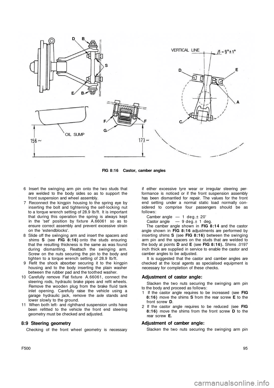
FIG 8:16 Castor, camber angles
6 Insert the swinging arm pin onto the two studs that
are welded to the body sides so as to support the
front suspension and wheel assembly.
7 Reconnect the kingpin housing to the spring eye by
inserting the bolt and tightening the self-locking nut
to a torque wrench setting of 28.9 Ib/ft. It is important
that during this operation the spring is always kept
in the 'set' position by fixture A.66061 so as to
ensure correct assembly and prevent excessive strain
on the 'estendblocks'.
8 Slide off the swinging arm and insert the spacers and
shims S (see FIG 8:16) onto the studs ensuring
that the resulting thickness is the same as was found
during dismantling. Reattach the swinging arm.
Screw on the nuts securing the pin to the body and
tighten to a torque wrench setting of 28.9 Ib/ft.
9 Refit the shock absorber securing it to the kingpin
housing and to the body inserting the plain washer
between the rubber pad and the toothed washer.
10 Carefully remove Fiat fixture A.66061, connect the
steering rods, hydraulic brake pipes and refit wheels.
Remove the wooden plug from the brake fluid tank
inlet opening. Carefully raise the vehicle using a
garage hydraulic jack, remove the axle stands and
lower slowly to the ground.
11 When both left- and righthand suspension units have
been refitted to the vehicle the front end steering
geometry must be checked and adjusted.
8:9 Steering geometry
Checking of the front wheel geometry is necessary
95
F500
if either excessive tyre wear or irregular steering per-
formance is noticed or if the front suspension assembly
has been dismantled for repair. The values for the front
end setting under a normal static load normally con-
sidered to comprise four passengers should be as
follows:
Camber angle — 1 d e g . ± 20'
Castor angle — 9 deg.± 1 deg.
The camber angle shown in FIG 8:14 and the castor
angle shown in FIG 8 : 1 6 adjustments are performed by
inserting shims S (see FIG 8 : 1 6 ) between the swinging
arm pin and the spacers on the studs that are welded to
the body at points D and E (see FIG 8:16). Shims .0197
inch thick are supplied in service to enable the castor and
camber angles to be adjusted.
It is suggested that the castor and camber angles are
checked at the local agents as specialised equipment is
necessary for completion of these checks.
Adjustment of castor angle:
Slacken the t w o nuts securing the swinging arm pin
to the body and proceed as follows:
1 If the castor angle requires to be increased (see FIG
8:16) move the shims S from the rear screw E to the
front screw D.
2 If the castor angle requires to be reduced (see FIG
8:16) move the shims from the front screw D to the
rear screw E.
Adjustment of camber angle:
Slacken the t w o nuts securing the swinging arm pin DE
A
C
Page 89 of 128
to the body and proceed as follows:
1 If the camber angle requires to be increased (see FIG
8:16) add the same number of shims S on both
screws D and E.
2 If the camber angle requires to be reduced (see FIG
8:16) remove the same number of shims from both
screws D and E.
The addition or removal of shims at the t w o points D
and E permits camber adjustment to be made without
any disturbing of the castor angle.
8:10 Modifications
Checking and adjusting castor and camber angles:
When checking the castor and camber angle the
static loading should be such that the distance between
the semi-elliptic spring mountings G (see FIG 8:16)
and the floor level to be approximately 6.81 inches, also a
distance between the lowermost portion of the sump and
the floor level of approximately 6.14 inch for the Model
500D. For the 500 Station Wagon version the distance
between centre rear bracket for jacking-up the vehicle
and the floor level should be approximately 8.90 inches.
All other front wheel alignment specifications are the
same as for the remaining 500 saloon models.
8:11 Fault diagnosis
(a) Wheel bounce
1 Tyre casing faulty
2 Uneven tyre pressures
3 Wheels out of balance
4 Semi-elliptic mounting spring worn5 Weak or seized shock absorber
6 Wheel rim or tyre misaligned
(b) Suspension noise
1 Lack of lubrication
2 Noisy or inoperative shock absorbers
3 Worn or loose wheel bearings
(c) Pull to one side
1 Low or uneven tyre pressures
2 Incorrect front wheel alignment
3 Suspension arms distorted
4 Inoperative shock absorbers
5 Brakes binding
(d) Excessive t y r e wear
1 Incorrect tyre rotation during servicing periods
2 Incorrect camber angle
3 Incorrect toe-in
4 Incorrect tyre inflation
5 Excessive play at wheel bearings
6 Wheel wobble
7 Stiff suspension arms
8 Brakes out of adjustment
(e) Wheel wobble
1 Uneven tyre pressures
2 Loose or worn wheel bearings
3 Inoperative shock absorbers
4 Loose steering knuckle or kingpin housing
5 Incorrect front wheel alignment
6 Control arm rubber bushings, or kingpin housing and
semi-elliptic spring 'estendblock' worn
96
Page 95 of 128
normal straight-ahead position with the spokes
horizontal. Check that the wheels are in the straight-
ahead position.
2 Load the vehicle to static load conditions or with four
average size passengers.
3 Move the vehicle forwards for a distance of approxi-
mately six yards so that the suspension may settle
correctly.
4 The toe-in measurements should be taken at the same
point of the wheel rim. Measure at A (see FIG 9 : 8)
then back up the car to bring points A to the position B
and remeasure. The value obtained at A should be
equal to or greater than B within .0079 inch.
5 As previously described the steering rods are adjust-
able in length. Loosen the clamps and screw in or out
the adjusting sleeves and before tightening the clamp
ensure that the sleeve slot registers w i t h the clamp
joint. With the clamp fully tightened there should
always be a gap between the joint faces.
6 If the steering gear has been re-installed the correct
front wheel toe-in must be set. Then the relay lever pin
nut must be tightened to a torque wrench setting of 78
to 85 Ib/ft.
9 : 8 Fault diagnosis
(a) Front wheel shimmy
1 Incorrect tyre pressure
2 Incorrect front wheel alignment
3 Loose front wheel bearings
4 Wheels out of balance
5 Loose steering linkage connections
6 Loose steering gear or relay lever support at body
mountings
7 Incorrect fitting of steering worm to worm sector
(b) Hard steering
1 Incorrect tyre pressure
2 Incorrect front wheel alignment
3 Incorrect adjustment of steering worm to worm sector
(c) Hard turning when stationary
1 Incorrect tyre pressure
2 Incorrect adjustment of steering worm to worm sector
102
(d) Pull to one side
1 Incorrect tyre pressure
2 Incorrect front wheel alignment
3 Incorrect front wheel bearing adjustment
4 Distorted kingpin housing or swinging arms
5 Unequal brake adjustment
6 Semi-elliptic spring weak or broken
(e) Rattles
1 Loose steering linkage connections
2 Loose steering gear or relay lever support at body
mountings
3 Semi-elliptic spring weak or broken
4 Lack of lubrication
( f ) Loose steering
1 Incorrect front wheel bearing adjustment
2 Loose steering linkage connections
3 Loose steering gear mountings
4 Incorrect adjustment of steering worm to worm sector
(g) Jerky steering
1 Incorrect front wheel alignment
2 Incorrect front wheel bearing adjustment
3 Wheels out of balance
4 Loose steering linkage connections
5 Loose or incorrect fitting of worm to sector
(h) Side-to-side wander
1 Incorrect tyre pressure
2 Incorrect front wheel alignment
3 Loose steering linkage connections
4 Loose steering gear or relay lever support at body
mountings
5 Incorrect fitting of steering worm to worm sector
6 Distorted kingpin housing or swinging arm
7 Semi-elliptic spring weak or broken
(i) Tyre squeal on turns
1 Incorrect tyre pressure
2 Incorrect wheel alignment
3 Distorted kingpin housing or swinging arms
Page 96 of 128
CHAPTER 10
THE BRAKING SYSTEM
10:1 Description
10:2 Maintenance
10:3 Front brakes
10:4 Rear brakes
10:5 Master cylinder
10:6 Wheel cylinder10:7 Self-adjusting device
10:8 Removing a flexible hose
10:9 Brake fluid reservoir
10:10 Bleeding the system
10:11 Hand parking brake
10:12 Fault diagnosis
10:1 Description
All four drum brake units are hydraulically operated by
the brake pedal and the handbrake lever operates the rear
brakes only through a mechanical linkage which normally
requires no separate adjustment (see FIG 10:1).
The brake units are of the internal expanding type with
one leading and one trailing shoe to each brake. A double
ended wheel cylinder expands both shoes into contact
with the drum under hydraulic pressure from the master
cylinder. When the brake pedal pressure is released the
shoes are retracted by means of springs.
The brake pedal is directly coupled to the hydraulic
master cylinder where pressure on the fluid is generated.
This is transmitted to the brakes by a system of metal and
flexible pipes.
The braking units fitted to the new 500 Sedan models
are equipped with a specially designed brake shoe
clearance self-adjustment device which eliminates the
need for manual adjustment of the brake shoe to drum
clearance as is normal practice w i t h a conventional
braking system. Every time the brake pedal is depressed
the self-adjustment device automatically takes up the
excess clearance which may have developed between
the lining and the drum due to normal service wear.
The brake units fitted to the 500 Station wagon model
have a normal brake adjuster which should be used when
F500103 the brake pedal travel becomes excessive. The adjuster
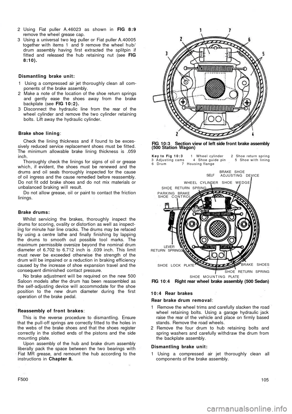
is shown in FIG 10:3.
On later models a dual circuit system is used. It is
described in Section 10:12
10:2 Maintenance
Brake adjustment {Station Wagon)
Jack each wheel in turn after first chocking the remain-
ing three wheels and releasing the handbrake. Depress
the brake pedal so as to force the brake shoes against the
drum and keeping the shoes in this position turn the
adjuster nuts until they contact the shoes and then back
the nuts 20 deg. This will correctly set the shoe to drum
clearance which should be checked for binding by
releasing the brake pedal and ensuring that the road wheel
revolves freely. The operation should then be repeated
on the other wheels. This adjustment will automatically
set the handbrake.
Preventative maintenance:
1 Thoroughly inspect the metal hydraulic fluid lines for
rusting, cracking or flattening and that they are
located away from any sharp edges which could cause
a failure.
Page 97 of 128
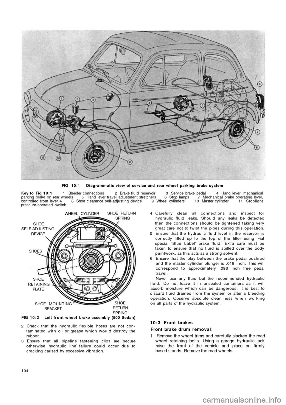
FIG 10:1 Diagrammatic view of service and rear wheel parking brake system
Key to Fig 10:1 1 Bleeder connections 2 Brake fluid reservoir 3 Service brake pedal 4 Hand lever, mechanical
parking brake on rear wheels 5 Hand lever travel adjustment stretchers 6 Stop lamps 7 Mechanical brake operating lever,
controlled from lever 4 8 Shoe clearance self-adjusting device 9 Wheel cylinders 10 Master cylinder 11 Stoplight
pressure-operated switch
FIG 10:2 Left front wheel brake assembly (500 Sedan)
SHOE
RETURN
SPRINGSHOE MOUNTING
BRACKET SHOE
RETAINING
PLATE SHOES
DEVICESHOE
SELF-ADJUSTING
WHEEL CYLINDERSHOE RETURNSPRING
2 Check that the hydraulic flexible hoses are not con-
taminated with oil or grease which would destroy the
rubber.
3 Ensure that all pipeline fastening clips are secure
otherwise hydraulic line failure could occur due to
cracking caused by excessive vibration.
104
4 Carefully clean all connections and inspect for
hydraulic fluid leaks. Should any leaks be detected
then the connections should be tightened taking very
great care not to twist the pipes during this operation.
5 Ensure that the hydraulic fluid level in the reservoir is
correctly filled up to the top of the filter using Fiat
special 'Blue Label' brake fluid. Extra care must be
taken to ensure that no fluid is spilled over the body
paintwork, as this acts as a strong solvent.
6 Ensure that the play between the brake pedal pushrod
and the master cylinder plunger is .019 inch. This will
correspond to approximately .098 inch free pedal
travel.
Never use any fluid but the recommended hydraulic
fluid. Do not leave it in unsealed containers as it will
absorb moisture which can be dangerous. It is best to
discard fluid drained from the system or after a bleeding
operation. Observe absolute cleanliness when working
on all parts of the hydraulic system.
10:3 Front brakes
Front brake drum removal:
1 Remove the wheel trims and carefully slacken the road
wheel retaining bolts. Using a garage hydraulic jack
raise the front of the vehicle and place on firmly
based stands. Remove the road wheels.
Page 98 of 128
2 Using Fiat puller A.46023 as shown in FIG 8 : 9
remove the wheel grease cap.
3 Using a universal t w o leg puller or Fiat puller A.40005
together w i t h items 1 and 9 remove the wheel hub/
drum assembly having first extracted the splitpin if
fitted and released the hub retaining nut (see FIG
8:10).
Dismantling brake unit:
1 Using a compressed air jet thoroughly clean all com-
ponents of the brake assembly.
2 Make a note of the location of the shoe return springs
and gently ease the shoes away from the brake
backplate (see FIG 10:2).
3 Disconnect the hydraulic line from the rear of t h e
wheel cylinder and remove the t w o cylinder retaining
bolts. Lift away the hydraulic cylinder.
Brake shoe lining:
Check the lining thickness and if found to be exces-
sively reduced service replacement shoes must be fitted.
The minimum allowable brake lining thickness is .059
inch.
Thoroughly check the linings for signs of oil or grease
which, if evident, the shoes must be renewed and the
drums and oil seals thoroughly inspected for the cause
of oil ingress and the cause remedied before reassembly.
Do not fit odd brake shoes and do not mix materials or
unbalanced braking will result.
Do not allow grease, oil or paint to contact the friction
linings.
Brake drums:
Whilst servicing the brakes, thoroughly inspect the
drums for scoring, ovality or distortion as well as inspect-
ing for minute hair line cracks. The drums may be refaced
by using a centre lathe and finally finishing by lapping
the drums to smooth out possible tool marks. The
maximum permissible oversize beyond the nominal drum
diameter of 6.702 to 6.712 inch is .039 inch. This limit
must never be exceeded otherwise the strength of the
drum will be impaired or a reduction in braking efficiency
caused by the increase of shoe expansion travel and the
consequent diminished contact pressure.
No brake adjustment will be required on the new 500
Saloon models after the drum has been reassembled as
the self-adjusting device will accommodate for the shoe
position to the new drum diameter during the first
operation of the brake pedal.
Reassembly of front brakes:
This is the reverse procedure to dismantling. Ensure
that the pull-off springs are correctly fitted to the holes in
the webs of the brake shoes and that the shoes register
correctly in the slotted ends of the pistons and the
side
mounting plate.
Upon assembly of the hub and brake drum assembly
liberally pack the space between the two bearings w i t h
Fiat MR grease, and remount the hub according to the
instructions in Chapter 8.
F500
FIG 10:3 Section view of left side f r o n t brake assembly
(500 Station Wagon)
Key to Fig 10:3 1 Wheel cylinder 2 Shoe return spring
3 Adjusting cams 4 Shoe guide pin 5 Shoe with lining
6 Drum 7 Housing flange
BRAKE SHOE
ADJUSTING DEVICE
SHOE WEDGE
SELF
WHEEL CYLINDER
SHOE RETURN SPRING
PARKING BRAKE
SHOE CONTROL
RETURN SPRINGS
LEVER
SHOE LOCK PLATEBRAKE SHOES
SHOE RETURN SPRING
SHOE MOUNTING PLATE
FIG 1 0:4 Right rear wheel brake assembly (500 Sedan)
10:4 Rear brakes
Rear brake drum removal:
1 Remove the wheel trims and carefully slacken the road
wheel retaining bolts. Using a garage hydraulic jack
raise the rear of t h e vehicle and place on firmly based
stands. Remove the road wheels.
2 Remove the four drum to hub retaining bolts and
spring washers and carefully withdraw the drum from
the backplate assembly.
Dismantling brake unit:
1 Using a compressed air jet thoroughly clean all
components of the brake assembly.
105
Page 99 of 128
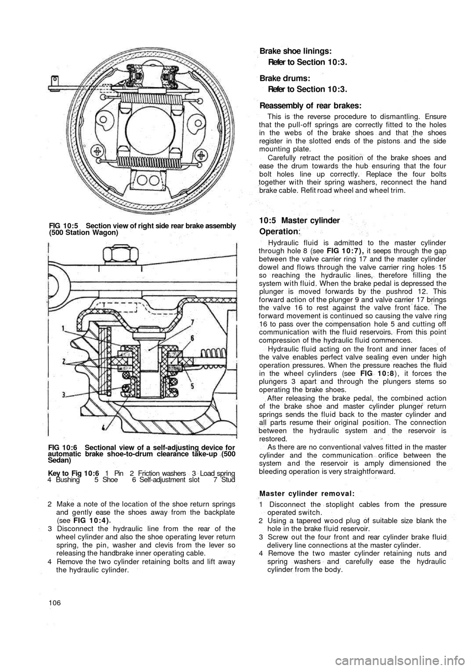
FIG 10:5 Section view of right side rear brake assembly
(500 Station Wagon)
FIG 10:6 Sectional view of a self-adjusting device for
automatic brake shoe-to-drum clearance take-up (500
Sedan)
Key to Fig 1 0 : 6 1 Pin 2 Friction washers 3 Load spring
4 Bushing 5 Shoe 6 Self-adjustment slot 7 Stud
2 Make a note of the location of the shoe return springs
and gently ease t h e shoes away from the backplate
(see FIG 10:4)
3 Disconnect the hydraulic line from the rear of t h e
wheel cylinder and also the shoe operating lever return
spring, the pin, washer and clevis from the lever so
releasing the handbrake inner operating cable.
4 Remove the t w o cylinder retaining bolts and lift away
the hydraulic cylinder.
106
Brake shoe linings:
Refer t o Section 10:3.
Brake drums:
Refer to Section 10:3.
Reassembly of rear brakes:
This is the reverse procedure to dismantling. Ensure
that the pull-off springs are correctly fitted to the holes
in the webs of the brake shoes and that the shoes
register in the slotted ends of the pistons and the side
mounting plate.
Carefully retract the position of the brake shoes and
ease t h e d r u m towards the hub ensuring that the four
bolt holes line up correctly. Replace the four bolts
together with their spring washers, reconnect the hand
brake cable. Refit road wheel and wheel trim.
10:5 Master cylinder
Operation:
Hydraulic fluid is admitted to the master cylinder
through hole 8 (see FIG 10:7), it seeps through the gap
between the valve carrier ring 17 and the master cylinder
dowel and flows through the valve carrier ring holes 15
so reaching the hydraulic lines, therefore filling the
system w i t h fluid. When the brake pedal is depressed the
plunger is moved forwards by the pushrod 12. This
forward action of the plunger 9 and valve carrier 17 brings
the valve 16 to rest against the valve front face. The
forward movement is continued so causing the valve ring
16 to pass over the compensation hole 5 and cutting off
communication with the fluid reservoirs. From this point
compression of the hydraulic fluid commences.
Hydraulic fluid acting on the front and inner faces of
the valve enables perfect valve sealing even under high
operation pressures. When the pressure reaches the fluid
in the wheel cylinders (see FIG 10:8) , it forces the
plungers 3 apart and through the plungers stems so
operating the brake shoes.
After releasing the brake pedal, the combined action
of the brake shoe and master cylinder plunger return
springs sends the fluid back to the master cylinder and
all parts resume their original position. The connection
between the hydraulic
system and the reservoir is
restored.
As there are no conventional valves fitted in the master
cylinder and the communication orifice between the
system a n d the reservoir is amply dimensioned the
bleeding operation is very straightforward.
Master cylinder removal:
1 Disconnect the stoplight cables from the pressure
operated switch.
2 Using a tapered w o o d plug of suitable size blank t h e
hole in the brake f l u i d reservoir.
3 Screw out the four front and rear cylinder brake fluid
delivery line connections at the master cylinder.
4 Remove the t w o master cylinder retaining nuts and
spring washers and carefully ease the hydraulic
cylinder from the body.
Page 100 of 128
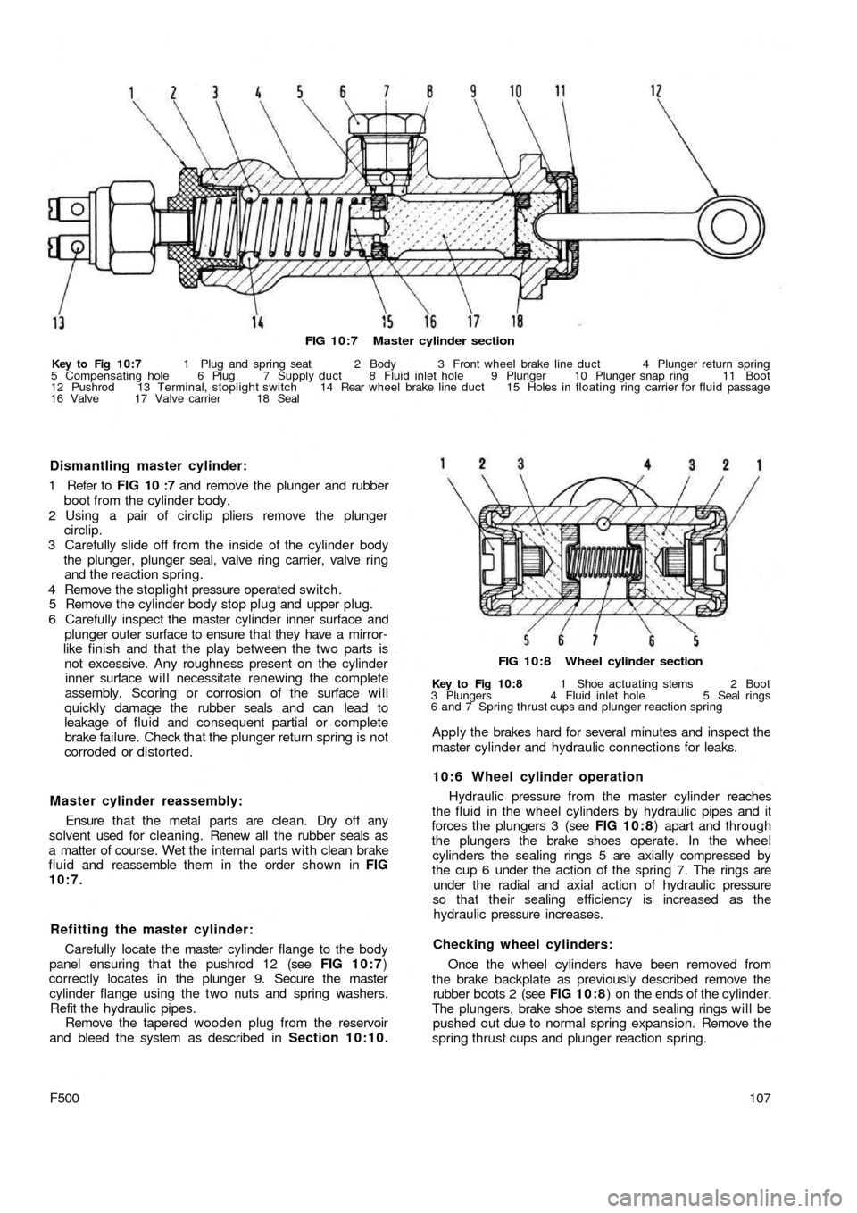
FIG 10:7 Master cylinder section
Key to Fig 10:7 1 Plug and spring seat 2 Body 3 Front wheel brake line duct 4 Plunger return spring
5 Compensating hole 6 Plug 7 Supply duct 8 Fluid inlet hole 9 Plunger 10 Plunger snap ring 11 Boot
12 Pushrod 13 Terminal, stoplight switch 14 Rear wheel brake line duct 15 Holes in floating ring carrier for fluid passage
16 Valve 17 Valve carrier 18 Seal
FIG 10:8 Wheel cylinder section
Key to Fig 10:8 1 Shoe actuating stems 2 Boot
3 Plungers 4 Fluid inlet hole 5 Seal rings
6 and 7 Spring thrust cups and plunger reaction spring
Apply the brakes hard for several minutes and inspect the
master cylinder and hydraulic connections for leaks.
10:6 Wheel cylinder operation
Hydraulic pressure from the master cylinder reaches
the fluid in the wheel cylinders by hydraulic pipes and it
forces the plungers 3 (see FIG 1 0 : 8) apart and through
the plungers the brake shoes operate. In the wheel
cylinders the sealing rings 5 are axially compressed by
the cup 6 under the action of the spring 7. The rings are
under the radial and axial action of hydraulic pressure
so that their sealing efficiency is increased as the
hydraulic pressure increases.
Checking wheel cylinders:
Once the wheel cylinders have been removed from
the brake backplate as previously described remove the
rubber boots 2 (see FIG 10:8) on the ends of the cylinder.
The plungers, brake shoe stems and sealing rings will be
pushed out due to normal spring expansion. Remove the
spring thrust cups and plunger reaction spring.
107F500
Master cylinder reassembly:
Ensure that the metal parts are clean. Dry off any
solvent used for cleaning. Renew all the rubber seals as
a matter of course. Wet the internal parts w i t h clean brake
fluid and reassemble them in the order shown in FIG
10:7.
Refitting the master cylinder:
Carefully locate the master cylinder flange to the body
panel ensuring that the pushrod 12 (see FIG 10:7)
correctly locates in the plunger 9. Secure the master
cylinder flange using the t w o nuts and spring washers.
Refit the hydraulic pipes.
Remove the tapered wooden plug from the reservoir
and bleed the system as described in Section 10:10. Dismantling master cylinder:
1 Refer to FIG 10 :7 and remove the plunger and rubber
boot from the cylinder body.
2 Using a pair of circlip pliers remove the plunger
circlip.
3 Carefully slide off from the inside of the cylinder body
the plunger, plunger seal, valve ring carrier, valve ring
and the reaction spring.
4 Remove the stoplight pressure operated switch.
5 Remove the cylinder body stop plug and upper plug.
6 Carefully inspect the master cylinder inner surface and
plunger outer surface to ensure that they have a mirror-
like finish and that the play between the two parts is
not excessive. Any roughness present on the cylinder
inner surface will necessitate renewing the complete
assembly. Scoring or corrosion of the surface will
quickly damage the rubber seals and can lead to
leakage of fluid and consequent partial or complete
brake failure. Check that the plunger return spring is not
corroded or distorted.
Page 101 of 128
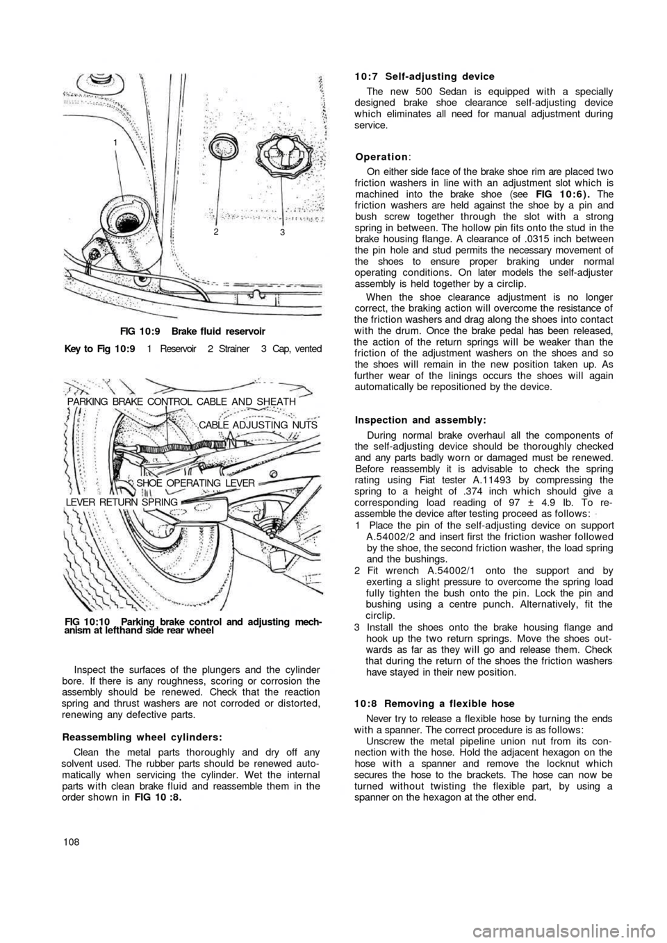
FIG 10:9 Brake fluid reservoir
Key to Fig 1 0 : 9 1 Reservoir 2 Strainer 3 Cap, vented
PARKING BRAKE CONTROL CABLE AND SHEATH
.CABLE ADJUSTING NUTS
SHOE OPERATING LEVER
LEVER RETURN SPRING
FIG 10:10 Parking brake control and adjusting mech-
anism at lefthand side rear wheel
Inspect the surfaces of the plungers and the cylinder
bore. If there is any roughness, scoring or corrosion the
assembly should be renewed. Check that the reaction
spring and thrust washers are not corroded or distorted,
renewing any defective parts.
Reassembling wheel cylinders:
Clean the metal parts thoroughly and dry off any
solvent used. The rubber parts should be renewed auto-
matically when servicing the cylinder. Wet the internal
parts w i t h clean brake f l u i d and reassemble them in the
order shown in FIG 10 : 8 .
10810:7 Self-adjusting device
The new 500 Sedan is equipped with a specially
designed brake shoe clearance self-adjusting device
which eliminates all need for manual adjustment during
service.
Operation:
On either side face of the brake shoe rim are placed t w o
friction washers in line with an adjustment slot which is
machined into the brake shoe (see FIG 10:6). The
friction washers are held against the shoe by a pin and
bush screw together through the slot with a strong
spring in between. The hollow pin fits onto the stud in the
brake housing flange. A clearance of .0315 inch between
the pin hole and stud permits the necessary movement of
the shoes to ensure proper braking under normal
operating conditions. On later models the self-adjuster
assembly is held together by a circlip.
When the shoe clearance adjustment is no longer
correct, the braking action will overcome the resistance of
the friction washers and drag along the shoes into contact
with the drum. Once the brake pedal has been released,
the action of the return springs will be weaker than the
friction of the adjustment washers on the shoes and so
the shoes will remain in the new position taken up. As
further wear of the linings occurs the shoes will again
automatically be repositioned by the device.
Inspection and assembly:
During normal brake overhaul all the components of
the self-adjusting device should be thoroughly checked
and any parts badly worn or damaged must be renewed.
Before reassembly it is advisable to check the spring
rating using Fiat tester A.11493 by
compressing the
spring to a height of .374 inch which should give a
corresponding load reading of 97 ± 4.9 Ib. To re-
assemble the device after testing proceed as follows:
1 Place the pin of the self-adjusting device on support
A.54002/2 and insert first the friction washer followed
by the shoe, the second friction washer, the load spring
and the bushings.
2 Fit wrench A.54002/1 onto the support and by
exerting a slight pressure to overcome the spring load
fully tighten the bush onto the pin. Lock the pin and
bushing using a centre punch. Alternatively, fit the
circlip.
3 Install the shoes onto the brake housing flange and
hook up the t w o return springs. Move the shoes out-
wards as far as they will go and release them. Check
that during the return of the shoes the friction washers
have stayed in their new position.
10:8 Removing a flexible hose
Never try to release a flexible hose by turning the ends
w i t h a spanner. The correct procedure is as follows:
Unscrew the metal pipeline union nut from its con-
nection with the hose. Hold the adjacent hexagon on the
hose w i t h a spanner and remove the locknut which
secures the hose to the brackets. The hose can now be
turned without twisting the flexible part, by using a
spanner on the hexagon at the other end.
1
2
3