lock FIAT 500 2020 Owner handbook (in English)
[x] Cancel search | Manufacturer: FIAT, Model Year: 2020, Model line: 500, Model: FIAT 500 2020Pages: 228, PDF Size: 6.01 MB
Page 104 of 228
129)Before starting any servicing
operation, stop the engine and remove the
key from the ignition switch to operate
the steering lock, particularly when the
wheels do not touch the ground. If this is
not possible (for example if the key needs
to be turned to MAR or the engine must be
running), remove the main fuse that
protects the electric power steering.START&STOP
SYSTEM
130) 131) 132) 133)
46)
(for versions/markets, where provided)
The Start&Stop system automatically
stops the engine each time the car
is stationary and starts it again when
the driver wants to move off.
In this way, the vehicle efficiency is
increased, by reducing consumption,
dangerous gas emissions and sound
pollution.
OPERATING MODE
Stopping the engine
With manual transmission: with the car
stationary, the engine stops with the
transmission in neutral and the clutch
pedal released.
With Dualogic gearbox: the engine
stops if the car is at a standstill and the
brake pedal is pressed. This condition
can be maintained even if the brake
pedal is not depressed, if the gear lever
is in position N (Neutral).NOTE The engine can only be stopped
automatically over about 10 km/h, to
prevent the engine from being
repeatedly stopped when driving at
walking pace.
Stopping of the engine is indicated by
the warning light or the symbol
on
the instrument panel switching on
(on some versions, together with a
message on the display).
Restarting the engine
With manual transmission: press the
clutch pedal.
With Dualogic gearbox: if the gear lever
is in position N (Neutral), place it in
any other gear, otherwise release the
brake pedal or move the gear lever
to+,–or R (Reverse).
MANUAL SYSTEM
ACTIVATION/
DEACTIVATION
The system can be activated/
deactivated by pressing the button A
fig. 79 on the dashboard.
With the system off, the warning light or
the symbol
appear on the
instrument panel (with a message for
versions with colour display).
Start&Stop mode will be active
whenever the engine is started.
102
STARTING AND DRIVING
Page 112 of 228
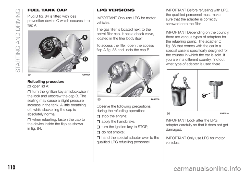
FUEL TANK CAP
Plug B fig. 84 is fitted with loss
prevention device C which secures it to
flap A.
Refuelling procedure
open lid A;
turn the ignition key anticlockwise in
the lock and unscrew the cap B. The
sealing may cause a slight pressure
increase in the tank. A little breathing
off, while slackening the cap is
absolutely normal;
when refuelling, fasten the cap to
the device inside the flap as shown
in fig. 84.LPG VERSIONS
IMPORTANT Only use LPG for motor
vehicles.
The gas filler is located next to the
petrol filler cap. It has a check valve,
located in the filler body itself.
To access the filler, open the access
flap A fig. 85 and undo the cap B.
Observe the following precautions
during the refuelling operation:stop the engine;
apply the handbrake;
turn the ignition key to STOP;
do not smoke;
hand the special adapter over to the
qualified LPG refuelling personnel.IMPORTANT Before refuelling with LPG,
the qualified personnel must make
sure that the adapter is correctly
screwed onto the filler.
IMPORTANT Depending on the country,
there are various types of adapters for
the refuelling pump. The adapter C
fig. 86 that comes with the car in a
special case is specifically designed for
the country in which the car is sold. If
you are in a different country, find out
what type of adapter is used there.
IMPORTANT Look after the LPG
adapter carefully so that it does not get
damaged.
IMPORTANT Only use LPG for motor
vehicles.
84F0S0104
85F0S0538
86F0S0539
110
STARTING AND DRIVING
Page 119 of 228
REPLACING AN
EXTERNAL BULB
FRONT LIGHT CLUSTERS
The front light clusters contain side
lights, dipped headlights, main beam
headlights and direction indicator bulbs.
Front direction indicators
(POP versions only)
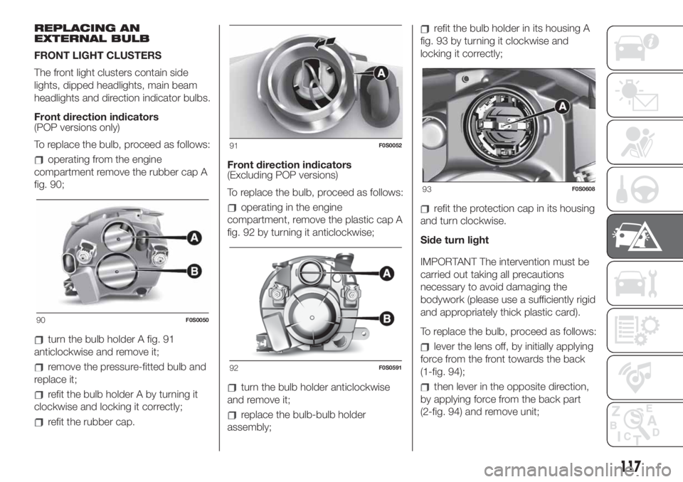
To replace the bulb, proceed as follows:
operating from the engine
compartment remove the rubber cap A
fig. 90;
turn the bulb holder A fig. 91
anticlockwise and remove it;
remove the pressure-fitted bulb and
replace it;
refit the bulb holder A by turning it
clockwise and locking it correctly;
refit the rubber cap.Front direction indicators
(Excluding POP versions)
To replace the bulb, proceed as follows:
operating in the engine
compartment, remove the plastic cap A
fig. 92 by turning it anticlockwise;
turn the bulb holder anticlockwise
and remove it;
replace the bulb-bulb holder
assembly;
refit the bulb holder in its housing A
fig. 93 by turning it clockwise and
locking it correctly;
refit the protection cap in its housing
and turn clockwise.
Side turn light
IMPORTANT The intervention must be
carried out taking all precautions
necessary to avoid damaging the
bodywork (please use a sufficiently rigid
and appropriately thick plastic card).
To replace the bulb, proceed as follows:
lever the lens off, by initially applying
force from the front towards the back
(1-fig. 94);
then lever in the opposite direction,
by applying force from the back part
(2-fig. 94) and remove unit;
90F0S0050
91F0S0052
92F0S0591
93F0S0608
117
Page 120 of 228
turn the bulb holder anticlockwise,
extract the press-fitted bulb and
replace it;
refit the bulb holder in the lens, then
position unit, ensuring that the fastening
clip clicks into place.
51)
Dipped beam headlights
(POP versions only)
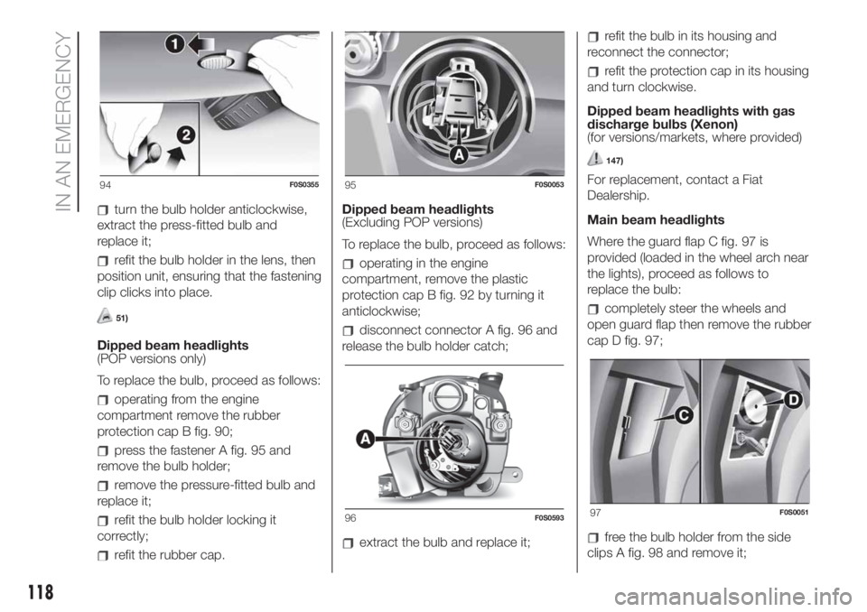
To replace the bulb, proceed as follows:
operating from the engine
compartment remove the rubber
protection cap B fig. 90;
press the fastener A fig. 95 and
remove the bulb holder;
remove the pressure-fitted bulb and
replace it;
refit the bulb holder locking it
correctly;
refit the rubber cap.Dipped beam headlights
(Excluding POP versions)
To replace the bulb, proceed as follows:
operating in the engine
compartment, remove the plastic
protection cap B fig. 92 by turning it
anticlockwise;
disconnect connector A fig. 96 and
release the bulb holder catch;
extract the bulb and replace it;
refit the bulb in its housing and
reconnect the connector;
refit the protection cap in its housing
and turn clockwise.
Dipped beam headlights with gas
discharge bulbs (Xenon)
(for versions/markets, where provided)
147)
For replacement, contact a Fiat
Dealership.
Main beam headlights
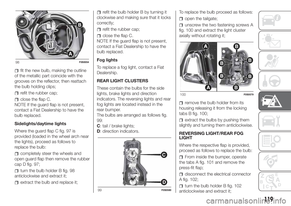
Where the guard flap C fig. 97 is
provided (loaded in the wheel arch near
the lights), proceed as follows to
replace the bulb:
completely steer the wheels and
open guard flap then remove the rubber
cap D fig. 97;
free the bulb holder from the side
clips A fig. 98 and remove it;
94F0S035595F0S0053
96F0S059397F0S0051
118
IN AN EMERGENCY
Page 121 of 228
fit the new bulb, making the outline
of the metallic part coincide with the
grooves on the reflector, then reattach
the bulb holding clips;
refit the rubber cap;
close the flap C.
NOTE If the guard flap is not present,
contact a Fiat Dealership to have the
bulb replaced.
Sidelights/daytime lights
Where the guard flap C fig. 97 is
provided (loaded in the wheel arch near
the lights), proceed as follows to
replace the bulb:
completely steer the wheels and
open guard flap then remove the rubber
cap D fig. 97;
turn the bulb holder B fig. 98
anticlockwise and extract it;
extract the bulb and replace it;
refit the bulb holder B by turning it
clockwise and making sure that it locks
correctly;
refit the rubber cap;
close the flap C.
NOTE If the guard flap is not present,
contact a Fiat Dealership to have the
bulb replaced.
Fog lights
To replace a fog light, contact a Fiat
Dealership.
REAR LIGHT CLUSTERS
These contain the bulbs for the side
lights, brake lights and direction
indicators. The reversing lights and rear
fog lights are located instead in the
rear bumper.
The bulbs are arranged as follows fig.
99:
C: tail / brake lights;
D: direction indicators.To replace the bulb proceed as follows:
open the tailgate;
unscrew the two fastening screws A
fig. 100 and extract the light cluster
axially without rotating it;
remove the bulb holder from its
housing releasing it from the locking
tabs B fig. 100;
extract the bulbs by pushing them
slightly and turning them anticlockwise.
REVERSING LIGHT/REAR FOG
LIGHT
Where the respective flap is provided,
proceed as follows to replace the bulb:
From inside the bumper, operate
the tabs A fig. 101 and remove the
press-fit flap;
disconnect the electrical connector
A fig. 102;
turn the bulb holder B fig. 102
anticlockwise and extract it;
98F0S0054
99F0S0580
100F0S0579
119
Page 122 of 228
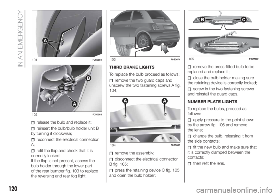
release the bulb and replace it;
reinsert the bulb/bulb holder unit B
by turning it clockwise;
reconnect the electrical connection
A;
refit the flap and check that it is
correctly locked.
If the flap is not present, access the
bulb holder through the lower part
of the rear bumper fig. 103 to replace
the reversing and rear fog light.THIRD BRAKE LIGHTS
To replace the bulb proceed as follows:
remove the two guard caps and
unscrew the two fastening screws A fig.
104;
remove the assembly;
disconnect the electrical connector
B fig. 105;
press the retaining device C fig. 105
and open the bulb holder;
remove the press-fitted bulb to be
replaced and replace it;
close the bulb holder making sure
the retaining device is correctly locked;
screw in the two fastening screws
and reinstall the guard caps.
NUMBER PLATE LIGHTS
To replace the bulbs, proceed as
follows:
apply pressure to the point shown
by the arrow fig. 106 and remove
the lens;
change the bulb, releasing it from
the side contacts;
fit the new bulb and make sure that
it is correctly clamped between the
contacts;
then refit the lens.
101F0S0581
102F0S0582
103F0S0674
104F0S0058
105F0S0059
120
IN AN EMERGENCY
Page 124 of 228

The dashboard fuse box shown is
located in the lower area next to the
pedal board.
ENGINE COMPARTMENT
JUNCTION BOX
52)
The fusebox is located on the right side
of the engine compartment. To access
the fuses, proceed as follows:
Fully press screw A fig. 109;
at the same time slowly rotate the
screw anticlockwise, until resistance is
encountered (do not overtighten);
slowly release the screw;
opening is indicated by the entire
screw head coming out of its seat;
remove cover B, sliding it upwards
on the side guides, as indicated in
the figure.Once the fuse has been replaced,
proceed as follows:
correctly refit the cover B in the side
guides of the casing;
slide it down completely from the
top;
fully tighten screw A using the
screwdriver provided;
at the same time slowly rotate the
screw clockwise, until resistance is
encountered (do not overtighten);
slowly release the screw;
closure is indicated by the securing
of the entire screw head in its housing.
The number identifying the electrical
component corresponding to each fuse
is shown on the control unit cover.
LPG versions
The LPG system components are
protected by specific fuses. Contact a
Fiat Dealership for replacement.
109F0S0606
122
IN AN EMERGENCY
Page 125 of 228
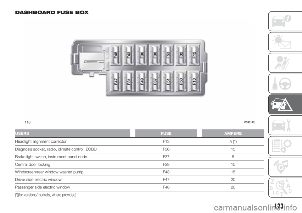
DASHBOARD FUSE BOX
USERSFUSE AMPERE
Headlight alignment corrector F13
5(*)
Diagnosis socket, radio, climate control, EOBD F36 15
Brake light switch, instrument panel node F37 5
Central door locking F38 15
Windscreen/rear window washer pump F43 15
Driver side electric window F47 20
Passenger side electric window F48 20
(*)(for versions/markets, where provided)
110F0S0172
123
Page 132 of 228
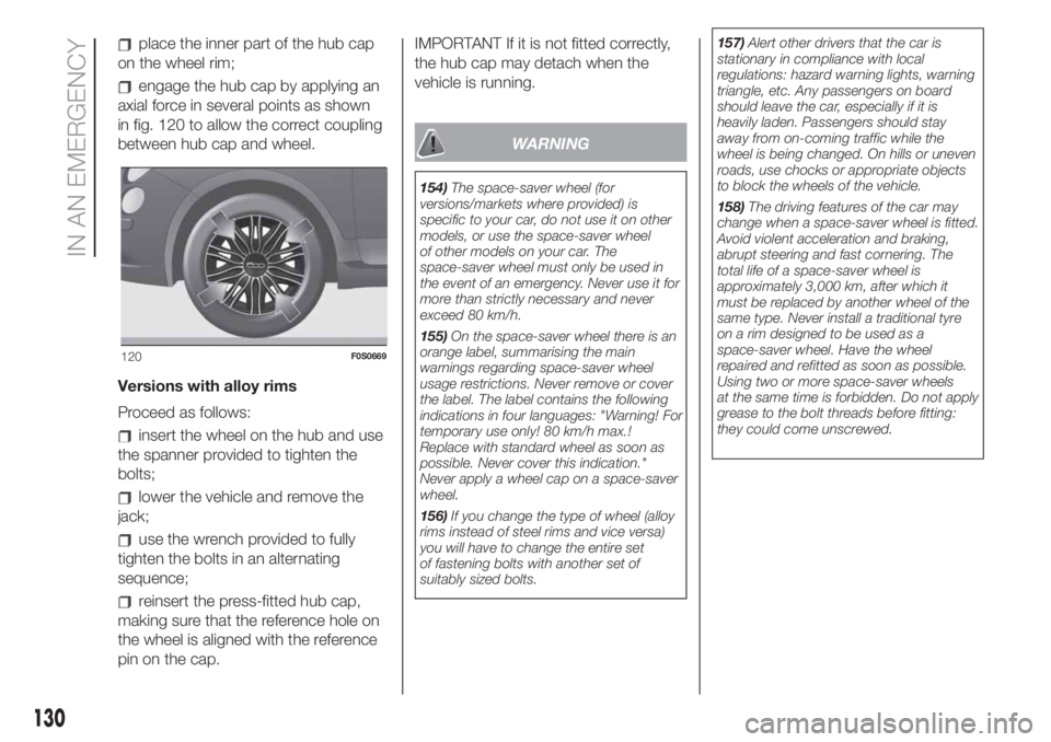
place the inner part of the hub cap
on the wheel rim;
engage the hub cap by applying an
axial force in several points as shown
in fig. 120 to allow the correct coupling
between hub cap and wheel.
Versions with alloy rims
Proceed as follows:
insert the wheel on the hub and use
the spanner provided to tighten the
bolts;
lower the vehicle and remove the
jack;
use the wrench provided to fully
tighten the bolts in an alternating
sequence;
reinsert the press-fitted hub cap,
making sure that the reference hole on
the wheel is aligned with the reference
pin on the cap.IMPORTANT If it is not fitted correctly,
the hub cap may detach when the
vehicle is running.
WARNING
154)The space-saver wheel (for
versions/markets where provided) is
specific to your car, do not use it on other
models, or use the space-saver wheel
of other models on your car. The
space-saver wheel must only be used in
the event of an emergency. Never use it for
more than strictly necessary and never
exceed 80 km/h.
155)On the space-saver wheel there is an
orange label, summarising the main
warnings regarding space-saver wheel
usage restrictions. Never remove or cover
the label. The label contains the following
indications in four languages: "Warning! For
temporary use only! 80 km/h max.!
Replace with standard wheel as soon as
possible. Never cover this indication."
Never apply a wheel cap on a space-saver
wheel.
156)If you change the type of wheel (alloy
rims instead of steel rims and vice versa)
you will have to change the entire set
of fastening bolts with another set of
suitably sized bolts.157)Alert other drivers that the car is
stationary in compliance with local
regulations: hazard warning lights, warning
triangle, etc. Any passengers on board
should leave the car, especially if it is
heavily laden. Passengers should stay
away from on-coming traffic while the
wheel is being changed. On hills or uneven
roads, use chocks or appropriate objects
to block the wheels of the vehicle.
158)The driving features of the car may
change when a space-saver wheel is fitted.
Avoid violent acceleration and braking,
abrupt steering and fast cornering. The
total life of a space-saver wheel is
approximately 3,000 km, after which it
must be replaced by another wheel of the
same type. Never install a traditional tyre
on a rim designed to be used as a
space-saver wheel. Have the wheel
repaired and refitted as soon as possible.
Using two or more space-saver wheels
at the same time is forbidden. Do not apply
grease to the bolt threads before fitting:
they could come unscrewed.
120F0S0669
130
IN AN EMERGENCY
Page 137 of 228
WARNING
166)This starting procedure must be
performed by expert personnel because
incorrect actions could cause electrical
discharge of considerable intensity.
Furthermore, battery fluid is poisonous and
corrosive: avoid contact with skin and
eyes. Keep naked flames and lighted
cigarettes away from the battery and do
not cause sparks.
167)Remove any metal objects (e.g. rings,
watches, bracelets), that might cause an
accidental electrical contact and cause
serious injury.
168)Do not attempt to charge a frozen
battery: it must be thawed first, otherwise it
may explode. If freezing has occurred, the
battery should be checked by skilled
personnel to make sure that the internal
elements are not damaged and that the
body is not cracked, with the risk of leaking
poisonous and corrosive acid.
WARNING
56)Never use a fast battery-charger to
start the engine as this could damage the
electronic systems of your vehicle,
particularly the ignition and engine fuel
supply control units.57)Do not connect the cable to the
negative terminal (–) of the flat battery. The
following spark could lead to battery
explosion and cause serious harm. Only
use the specific earth point; do not use any
other exposed metallic part.
58)Never bump start the engine by
pushing, towing or coasting downhill. This
could cause fuel to flow into the catalytic
converter and damage it beyond repair.
FUEL CUT-OFF
SYSTEM
169)
This intervenes in the case of an impact
causing:
the fuel supply cut-off with the
engine consequently switching off
the automatic unlocking of the doors
turning on of the lights inside the
vehicle;
The intervention of the system is
indicated by a message shown on the
display.
IMPORTANT Carefully check the car for
fuel leaks, for instance in the engine
compartment, under the car or near the
tank area. After a collision, turn the
ignition key to STOP position to prevent
the battery from running down.
To restore the correct operation of the
vehicle, proceed as follows:
turn the ignition key to the MAR-ON
position
activate the right direction indicator
deactivate the right direction
indicator
activate the left direction indicator
deactivate the left direction indicator
135