display FIAT 500 ABARTH 2013 2.G Owner's Manual
[x] Cancel search | Manufacturer: FIAT, Model Year: 2013, Model line: 500 ABARTH, Model: FIAT 500 ABARTH 2013 2.GPages: 84, PDF Size: 4.63 MB
Page 43 of 84

TRIP BUTTON
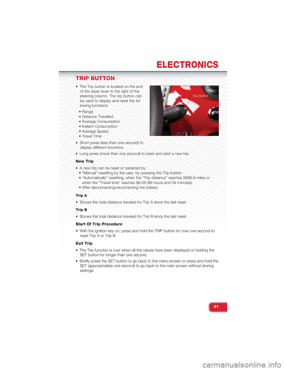
• The Trip button is located on the end
of the wiper lever to the right of the
steering column. The trip button can
be used to display and reset the fol-
lowing functions:
• Range
• Distance Travelled
• Average Consumption
• Instant Consumption
• Average Speed
• Travel Time
• Short press (less than one second) to
display different functions.
• Long press (more than one second) to reset and start a new trip.
New Trip
• A new trip can be reset or restarted by:
• “Manual” resetting by the user, by pressing the Trip button;
• “Automatically” resetting, when the “Trip distance” reaches 9999.9 miles or
when the “Travel time” reaches 99.59 (99 hours and 59 minutes);
• After disconnecting/reconnecting the battery.
Trip A
• Shows the total distance traveled for Trip A since the last reset.
Trip B
• Shows the total distance traveled for Trip B since the last reset.
Start Of Trip Procedure
• With the ignition key on, press and hold the TRIP button for over one second to
reset Trip A or Trip B.
Exit Trip
• The Trip function is over when all the values have been displayed or holding the
SET button for longer than one second.
• Briefly press the SET button to go back to the menu screen or press and hold the
SET (approximately one second) to go back to the main screen without storing
settings.
ELECTRONICS
41
Page 46 of 84

24-HOUR ROADSIDE ASSISTANCE
• If your Abarth requires jump start assistance, out of gas/fuel delivery, tire service,
lockout service or towing due to a defect covered under the Basic Limited War-
ranty, dial toll-free 1-888-242-6342. See your Warranty booklet for further details.
• Provide your name, vehicle identification number and license plate number.
• Provide your location, including telephone number, from which you are calling.
• Briefly describe the nature of the problem and answer a few simple questions.
• You will be given the name of the service provider and an estimated time of ar-
rival. If you feel you are in an “unsafe situation”, please let us know. With your
consent, we will contact local police or safety authorities.
INSTRUMENT CLUSTER WARNING LIGHTS
- Generic Warning Light
• The Generic Warning Light will illuminate if any of the following conditions occur:
Oil Change Request, Engine Oil Pressure Sensor Failure, After Run Cooling
Pump, External Light Failure, Fuel Cut-Off Intervention, Fuel Cut-Off Not Available,
Parking Sensor Failure.
- Power Steering System Warning
• If the “POWER STEERING SYSTEM OVER TEMP” message and icon are dis-
played in the Electronic Vehicle Information Center (EVIC) display, it indicates that
extreme steering maneuvers have occurred, which caused an over temperature
condition in the power steering system. You will lose power steering assistance
momentarily until the over temperature condition no longer exists. Once driving
conditions are safe, pull over and let the vehicle idle. After approximately five min-
utes, the system will cool and return to normal operation.
- Engine Temperature Warning Light
• This light warns of an overheated engine condition.
• If the light turns on or flashes continuously while driving, safely pull over and stop
the vehicle. If the A/C system is on, turn it off. Also, shift the transmission into
NEUTRAL and idle the vehicle. If the temperature reading does not return to nor-
mal, turn the engine off immediately.
• We recommend that you do not operate the vehicle or engine damage will occur.
Have the vehicle serviced immediately.
WARNING!
A hot engine cooling system is dangerous. You or others could be badly burned
by steam or boiling coolant. You may want to call an authorized studio for service
if your vehicle overheats.
WHAT TO DO IN EMERGENCIES
44
Page 60 of 84

• After the event occurs, when the system is active, the message "Fuel Cutoff See
Handbook" is displayed.
• Carefully check the vehicle for fuel leaks in the engine compartment and on the
ground near the engine compartment and fuel tank before resetting the system
and starting the engine.
NOTE:
In order to start the engine and move the vehicle to a safe location after an impact, the
System Reset Procedure must be completed.
System Reset Procedure
• After an impact causing air bag deployment, the left and right turn signal lights,
located in the instrument panel cluster, will both be blinking until the ignition is
turned off.
• In order to move your vehicle to the side of the road you must follow the system
reset procedure.
Customer Action Customer Will See
1. Turn ignition OFF. (Turn SignalSwitch must be placed in NeutralState).
2. Turn ignition ON. Left Turn Light is OFF. Right Turn LightBLINKS.
3. Turn Right Turn Signal Switch ON. Right Turn Light is ON SOLID. Left TurnLight BLINKS.
4. Turn Left Turn Signal Switch ON. Left Turn Light is ON SOLID. Right TurnLight BLINKS.
5. Turn Right Turn Signal Switch ON. Right Turn Light is ON SOLID. Left TurnLight BLINKS.
6. Turn Left Turn Signal Switch ON. Left Turn Light is ON SOLID. Right TurnLight is ON SOLID.
7. Turn Left Turn Signal Switch OFF.(Turn Signal Switch must be placed inNeutral State).
Left Turn Light is OFF. Right Turn Lightis OFF.
8. Turn ignition OFF. System is now reset and the enginemay be started.
9. Turn Hazard Flashers OFF (manually).
• If a reset procedure step is not completed within 45 seconds, then the turn signal
lights will turn off and the reset procedure must be performed again in order to be
successful.
WHAT TO DO IN EMERGENCIES
58
Page 66 of 84

MAINTENANCE SCHEDULE
Your vehicle is equipped with an automatic oil change indicator system. The oil
change indicator system will remind you that it is time to take your vehicle in for
scheduled maintenance.
Based on engine operation conditions, the oil change indicator message will illumi-
nate. This means that service is required for your vehicle. Operating conditions such
as frequent short-trips, trailer tow, extremely hot or cold ambient temperatures, and
E85 fuel usage will influence when the “Change Oil” message is displayed. Severe
Operating Conditions can cause the change oil message to illuminate as early as
3,500 miles (5,600 km) since last reset. Have your vehicle serviced as soon as pos-
sible, within the next 500 miles (805 km).
NOTE:Under no circumstances should oil change intervals exceed 10,000 miles (16,000 km) ortwelve months, whichever comes first.
Once A Month Or Before A Long Trip:
• Check engine oil level
• Check windshield washer fluid level
• Check the tire inflation pressures and look for unusual wear or damage
• Check the fluid levels of the coolant reservoir, brake master cylinder, and trans-
mission as needed
• Check function of all interior and exterior lights
Required Maintenance Intervals.
Refer to the Maintenance Schedules on the following pages for required mainte-
nance.
At Every Oil Change Interval As Indicated By Oil Change Indicator System:
•Change oil and filter.
• Rotate the tires. Rotate at the first sign of irregular wear, even if it occurs before theoil indicator system turns on.
•Inspect battery and clean and tighten terminals as required.
•Inspect brake pads, shoes, rotors, drums, hoses and park brake.
•Inspect engine cooling system protection and hoses.
•Inspect exhaust system.
•Inspect engine air cleaner if using in dusty or off-road conditions.
MAINTAINING YOUR VEHICLE
64