light FIAT 500 ABARTH 2013 2.G Owner's Manual
[x] Cancel search | Manufacturer: FIAT, Model Year: 2013, Model line: 500 ABARTH, Model: FIAT 500 ABARTH 2013 2.GPages: 84, PDF Size: 4.63 MB
Page 47 of 84
- Electronic Throttle Control (ETC) Light
•This light informs you of a problem with the Electronic Throttle Control (ETC) system.
• If a problem is detected, the light will come on while the engine is running. Cycle
the ignition when the vehicle has completely stopped; the light should turn off.
• If the light remains lit with the engine running, your vehicle will usually be drivable;
however, see an authorized service center immediately. If the light is flashing
when the engine is running, immediate service is required and you may experi-
ence reduced performance, an elevated/rough idle or engine stall and your ve-
hicle may require towing.
- Electronic Stability Control (ESC) OFF Indicator Light
• This light indicates the ESC system has been turned off by the driver.
- Electronic Stability Control (ESC) Activation / Malfunction
Indicator Light
• The “ESC Activation/Malfunction Indicator Light” in the instrument cluster will
come on for four seconds when the ignition switch is turned to the ON/RUN posi-
tion. If the “ESC Activation/Malfunction Indicator Light” comes on continuously
with the engine running, a malfunction has been detected in the ESC system.
If this light remains on, see your authorized studio as soon as possible to have
the problem diagnosed and corrected.
NOTE:
• The “ESC Off Indicator Light” and the “ESC Activation/Malfunction Indicator
Light” come on momentarily each time the ignition switch is turned to ON/RUN.
• Each time the ignition is turned to ON/RUN, the ESC system will be ON even if it
was turned off previously.
• ESC Activation/Malfunction Light can blink during a ESC or TC intervention.
TTC (Tire Transfer Control)
• The TTC system uses the brakes to prevent unwanted wheelspin during corner-
ing, to maximize acceleration and minimize understeering during aggressive driv-
ing. This feature is active in all modes. While TTC is active, the “ESC” lamp in the
instrument cluster may flash.
WHAT TO DO IN EMERGENCIES
45
Page 48 of 84
- Tire Pressure Monitoring System (TPMS) Light
• Each tire should be checked monthly when it is cold and inflated to the tire pres-
sure recommended by the vehicle manufacturer. This can be found on the ve-
hicle placard or tire inflation pressure label on the driver's door. (If your vehicle
has tires of a different size than the size indicated on the vehicle placard or tire
inflation pressure label, you should determine the proper tire inflation pressure for
those tires.)
• As an added safety feature, your vehicle has been equipped with a Tire Pressure
Monitoring System (TPMS) that illuminates a low tire pressure telltale when one or
more of your tires is significantly under-inflated. Accordingly, when the low tire
pressure telltale illuminates, you should stop and check your tires as soon as
possible, and inflate them to the proper pressure. Driving on a significantly under-
inflated tire causes the tire to overheat and can lead to tire failure. Under-inflation
also reduces fuel efficiency and tire tread life, and may affect the vehicle’s han-
dling and stopping ability.
•IF THE LIGHT STARTS FLASHING INDICATING A LOW TIRE PRES-
SURE, ADJUST THE AIR PRESSURE IN THE LOW TIRE TO THE AIR
PRESSURE SHOWN ON THE VEHICLE PLACARD OR TIRE INFLATION
PRESSURE LABEL LOCATED ON THE DRIVER'S DOOR. NOTE: AFTER
INFLATION, THE VEHICLE MAY NEED TO BE DRIVEN FOR 20 MIN-
UTES BEFORE THE FLASHING LIGHT WILL TURN OFF.
• Please note that the TPMS is not a substitute for proper tire maintenance, and it
is the driver’s responsibility to maintain correct tire pressure, even if under-
inflation has not reached the level to trigger illumination of the TPMS low tire pres-
sure telltale.
• Your vehicle has also been equipped with a TPMS malfunction indicator to indi-
cate when the system is not operating properly. The TPMS malfunction indicator
is combined with the low tire pressure telltale. When the system detects a mal-
function, the telltale will flash for approximately one minute and then remain con-
tinuously illuminated. This sequence will continue each time the vehicle is re-
started as long as the malfunction exists.
• When the malfunction indicator is illuminated, the system may not be able to de-
tect or signal low tire pressure as intended. TPMS malfunctions may occur for a
variety of reasons, including the installation of replacement or alternate tires or
wheels on the vehicle that prevent the TPMS from functioning properly. Always
check the TPMS malfunction telltale after replacing one or more tires or wheels
on your vehicle, to ensure that the replacement or alternate tires and wheels al-
low the TPMS to continue to function properly.
WHAT TO DO IN EMERGENCIES
46
Page 49 of 84
NOTE:
Tire pressures change by approximately 1 psi (7 kPa) per 12° F (7° C) of air tem-
perature change. Keep this in mind when checking tire pressure inside a garage,
especially in the winter. Example: If garage temperature is 68°F (20°C) and the out-
side temperature is 32°F (0°C), then the cold tire inflation pressure should be in-
creased by 3 psi (21 kPa), which equals 1 psi (7 kPa) for every 12°F (7°C) for this
outside temperature condition.
CAUTION!
The TPMS has been optimized for the original equipment tires and wheels. TPMS
pressures and warning have been established for the tire size equipped on your
vehicle. Undesirable system operation or sensor damage may result when using
replacement equipment that is not of the same size, type, and/or style. Aftermar-
ket wheels can cause sensor damage. Do not use tire sealant from a can, or bal-
ance beads if your vehicle is equipped with a TPMS, as damage to the sensors
may result.
BRAKE- Brake Warning Light
• The Brake Warning light illuminates when there is either a system malfunction or
the parking brake is applied. If the light is on and the parking brake is not applied,
it indicates a possible brake hydraulic malfunction, brake booster problem or an
Anti-Lock Brake System problem.
• Please have your vehicle serviced immediately.
WARNING!
Driving a vehicle with the red brake light on is dangerous. Part of the brake sys-
tem may have failed. It will take longer to stop the vehicle. You could have a colli-
sion. Have the vehicle checked immediately.
- Malfunction Indicator Light (MIL)
• Certain conditions, such as a loose or missing gas cap, poor fuel quality, etc.,
may illuminate the MIL after engine start. The vehicle should be serviced if the
light stays on through several typical driving cycles. In most situations, the vehicle
will drive normally and not require towing.
• If the MIL flashes when the engine is running, serious conditions may exist that
could lead to immediate loss of power or severe catalytic converter damage.
We recommend you do not operate the vehicle. Have the vehicle serviced
immediately.
WHAT TO DO IN EMERGENCIES
47
Page 50 of 84
- Charging System Light
• This light shows the status of the electrical charging system. If the charging sys-
tem light remains on, it means that the vehicle is experiencing a problem with the
charging system.
• We recommend you do not continue driving if the charging system light is on.
Have the vehicle serviced immediately.
- Oil Pressure Warning Light
• This light indicates low engine oil pressure. If the light turns on while driving, stop
the vehicle and shut off the engine as soon as possible. A chime will sound when
this light turns on.
• We recommend you do not operate the vehicle or engine damage will occur.
Have the vehicle serviced immediately.
- Anti-Lock Brake (ABS) Light
• This light monitors the Anti-Lock Brake System (ABS).
• If the light is not on during starting, stays on, or turns on while driving, we recom-
mend you drive to the nearest authorized studio immediately and have the vehicle
serviced immediately.
- Air Bag Warning Light
• If the light is not on during starting, stays on, or turns on while driving, have the
vehicle serviced by an authorized studio immediately.
IF YOUR ENGINE OVERHEATS
• In any of the following situations, you can reduce the potential for overheating by
taking the appropriate action.
• On the highways — slow down.
• In city traffic — while stopped, shift transmission into NEUTRAL, but do not in-
crease engine idle speed.
NOTE:There are steps that you can take to slow down an overheat condition:
• If your air conditioner (A/C) is on, turn it off. The A/C system adds heat to the en-
gine cooling system and turning the A/C off can help remove this heat.
• You can also turn the Temperature control to maximum heat, the Mode control to
floor and the Fan control to high. This allows the heater core to act as a supple-
ment to the radiator and aids in removing heat from the engine cooling system.
• If the temperature reading does not return to normal, turn the engine off immedi-
ately.
• We recommend that you do not operate the vehicle or engine damage will occur.
Have the vehicle serviced immediately.
WHAT TO DO IN EMERGENCIES
48
Page 59 of 84
TOWING A DISABLED VEHICLE
With Ignition Key
Manual Transmission
• Vehicle can be flat towed (all four wheels on the ground) with the transmission in
NEUTRAL.
• Vehicle can be towed with the front wheels elevated.
• Vehicle can be towed on a flatbed truck (all wheels off the ground).
NOTE:If it is necessary to use the accessories while being towed (wipers, defrosters, etc.), the keymust be in the ON/RUN position. Make certain the transmission remains in NEUTRAL.
Without The Ignition Key
• Special care must be taken when the vehicle is towed with the ignition in the
OFF/LOCK position. A dolly should be used under the front wheels if the rear
wheels are raised. Proper towing equipment is necessary to prevent damage to
the vehicle.
CAUTION!
• Failure to follow these towing methods can cause severe transmission dam-
age. Such damage is not covered by the New Vehicle Limited Warranty.
• If the vehicle being towed requires steering, the ignition switch must be in the
ON/RUN position.
• Do not attempt to use sling-type equipment when towing. When securing
the vehicle to a flatbed truck, do not attach to front or rear suspension com-
ponents. Damage to your vehicle may result from improper towing.
ENHANCED ACCIDENT RESPONSE SYSTEM
• In the event of an impact causing air bag deployment, if the communication net-
work remains intact, and the power remains intact, depending on the nature of
the event the Occupant Restraint Controller (ORC) will determine whether to have
the Enhanced Accident Response System perform the following functions:
• Cut off fuel to the engine.
• Flash hazard lights as long as the battery has power or until the ignition key is
turned off.
• Turn on the interior lights, which remain on as long as the battery has power or
until the ignition key is removed.
• Unlock the doors automatically.
WHAT TO DO IN EMERGENCIES
57
Page 60 of 84
• After the event occurs, when the system is active, the message "Fuel Cutoff See
Handbook" is displayed.
• Carefully check the vehicle for fuel leaks in the engine compartment and on the
ground near the engine compartment and fuel tank before resetting the system
and starting the engine.
NOTE:
In order to start the engine and move the vehicle to a safe location after an impact, the
System Reset Procedure must be completed.
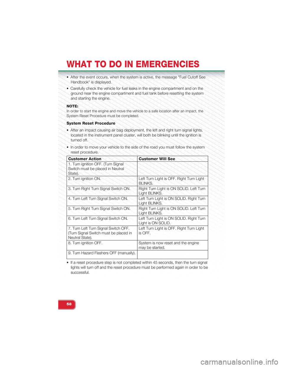
System Reset Procedure
• After an impact causing air bag deployment, the left and right turn signal lights,
located in the instrument panel cluster, will both be blinking until the ignition is
turned off.
• In order to move your vehicle to the side of the road you must follow the system
reset procedure.
Customer Action Customer Will See
1. Turn ignition OFF. (Turn SignalSwitch must be placed in NeutralState).
2. Turn ignition ON. Left Turn Light is OFF. Right Turn LightBLINKS.
3. Turn Right Turn Signal Switch ON. Right Turn Light is ON SOLID. Left TurnLight BLINKS.
4. Turn Left Turn Signal Switch ON. Left Turn Light is ON SOLID. Right TurnLight BLINKS.
5. Turn Right Turn Signal Switch ON. Right Turn Light is ON SOLID. Left TurnLight BLINKS.
6. Turn Left Turn Signal Switch ON. Left Turn Light is ON SOLID. Right TurnLight is ON SOLID.
7. Turn Left Turn Signal Switch OFF.(Turn Signal Switch must be placed inNeutral State).
Left Turn Light is OFF. Right Turn Lightis OFF.
8. Turn ignition OFF. System is now reset and the enginemay be started.
9. Turn Hazard Flashers OFF (manually).
• If a reset procedure step is not completed within 45 seconds, then the turn signal
lights will turn off and the reset procedure must be performed again in order to be
successful.
WHAT TO DO IN EMERGENCIES
58
Page 66 of 84
MAINTENANCE SCHEDULE
Your vehicle is equipped with an automatic oil change indicator system. The oil
change indicator system will remind you that it is time to take your vehicle in for
scheduled maintenance.
Based on engine operation conditions, the oil change indicator message will illumi-
nate. This means that service is required for your vehicle. Operating conditions such
as frequent short-trips, trailer tow, extremely hot or cold ambient temperatures, and
E85 fuel usage will influence when the “Change Oil” message is displayed. Severe
Operating Conditions can cause the change oil message to illuminate as early as
3,500 miles (5,600 km) since last reset. Have your vehicle serviced as soon as pos-
sible, within the next 500 miles (805 km).
NOTE:Under no circumstances should oil change intervals exceed 10,000 miles (16,000 km) ortwelve months, whichever comes first.
Once A Month Or Before A Long Trip:
• Check engine oil level
• Check windshield washer fluid level
• Check the tire inflation pressures and look for unusual wear or damage
• Check the fluid levels of the coolant reservoir, brake master cylinder, and trans-
mission as needed
• Check function of all interior and exterior lights
Required Maintenance Intervals.
Refer to the Maintenance Schedules on the following pages for required mainte-
nance.
At Every Oil Change Interval As Indicated By Oil Change Indicator System:
•Change oil and filter.
• Rotate the tires. Rotate at the first sign of irregular wear, even if it occurs before theoil indicator system turns on.
•Inspect battery and clean and tighten terminals as required.
•Inspect brake pads, shoes, rotors, drums, hoses and park brake.
•Inspect engine cooling system protection and hoses.
•Inspect exhaust system.
•Inspect engine air cleaner if using in dusty or off-road conditions.
MAINTAINING YOUR VEHICLE
64
Page 70 of 84
FUSES
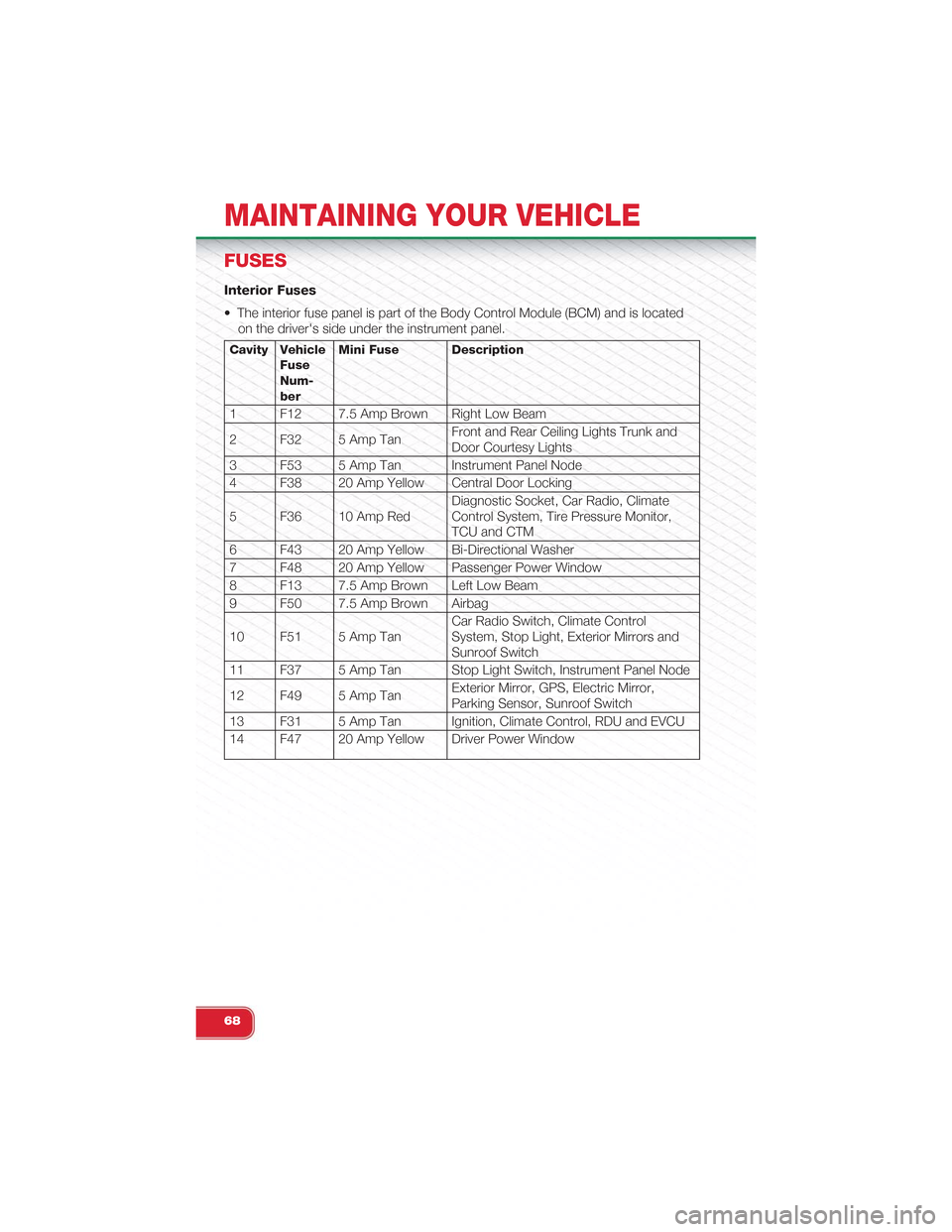
Interior Fuses
• The interior fuse panel is part of the Body Control Module (BCM) and is located
on the driver's side under the instrument panel.
Cavity VehicleFuseNum-ber
Mini Fuse Description
1 F12 7.5 Amp Brown Right Low Beam
2 F32 5 Amp TanFront and Rear Ceiling Lights Trunk andDoor Courtesy Lights
3 F53 5 Amp Tan Instrument Panel Node
4 F38 20 Amp Yellow Central Door Locking
5 F36 10 Amp RedDiagnostic Socket, Car Radio, ClimateControl System, Tire Pressure Monitor,TCU and CTM
6 F43 20 Amp Yellow Bi-Directional Washer
7 F48 20 Amp Yellow Passenger Power Window
8 F13 7.5 Amp Brown Left Low Beam
9 F50 7.5 Amp Brown Airbag
10 F51 5 Amp TanCar Radio Switch, Climate ControlSystem, Stop Light, Exterior Mirrors andSunroof Switch
11 F37 5 Amp Tan Stop Light Switch, Instrument Panel Node
12 F49 5 Amp TanExterior Mirror, GPS, Electric Mirror,Parking Sensor, Sunroof Switch
13 F31 5 Amp Tan Ignition, Climate Control, RDU and EVCU
14 F47 20 Amp Yellow Driver Power Window
MAINTAINING YOUR VEHICLE
68
Page 71 of 84
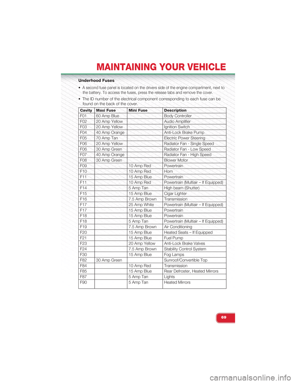
Underhood Fuses
•A second fuse panel is located on the drivers side of the engine compartment, next to
the battery. To access the fuses, press the release tabs and remove the cover.
• The ID number of the electrical component corresponding to each fuse can be
found on the back of the cover.
Cavity Maxi Fuse Mini Fuse Description
F01 60 Amp Blue Body Controller
F02 20 Amp Yellow Audio Amplifier
F03 20 Amp Yellow Ignition Switch
F04 40 Amp Orange Anti-Lock Brake Pump
F05 70 Amp Tan Electric Power Steering
F06 20 Amp Yellow Radiator Fan - Single Speed
F06 30 Amp Green Radiator Fan - Low Speed
F07 40 Amp Orange Radiator Fan - High Speed
F08 30 Amp Green Blower Motor
F09 10 Amp Red Powertrain
F10 10 Amp Red Horn
F11 15 Amp Blue Powertrain
F11 10 Amp Red Powertrain (Multiair – If Equipped)
F14 5 Amp Tan High beam (Shutter)
F15 15 Amp Blue Cigar Lighter
F16 7.5 Amp Brown Transmission
F17 25 Amp White Powertrain (Multiair – If Equipped)
F17 15 Amp Blue Powertrain
F18 15 Amp Blue Powertrain
F18 5 Amp Tan Powertrain (Multiair – If Equipped)
F19 7.5 Amp Brown Air Conditioning
F20 15 Amp Blue Heated Seats – If Equipped
F21 15 Amp Blue Fuel Pump
F23 20 Amp Yellow Anti-Lock Brake Valves
F24 7.5 Amp Brown Stability Control System
F30 15 Amp Blue Fog Lamps
F82 30 Amp Green Sunroof/Convertible Top
F84 10 Amp Red Transmission
F85 15 Amp Blue Rear Defroster, Heated Mirrors
F87 5 Amp Tan Lights
F90 5 Amp Tan Heated Mirrors
MAINTAINING YOUR VEHICLE
69
Page 74 of 84
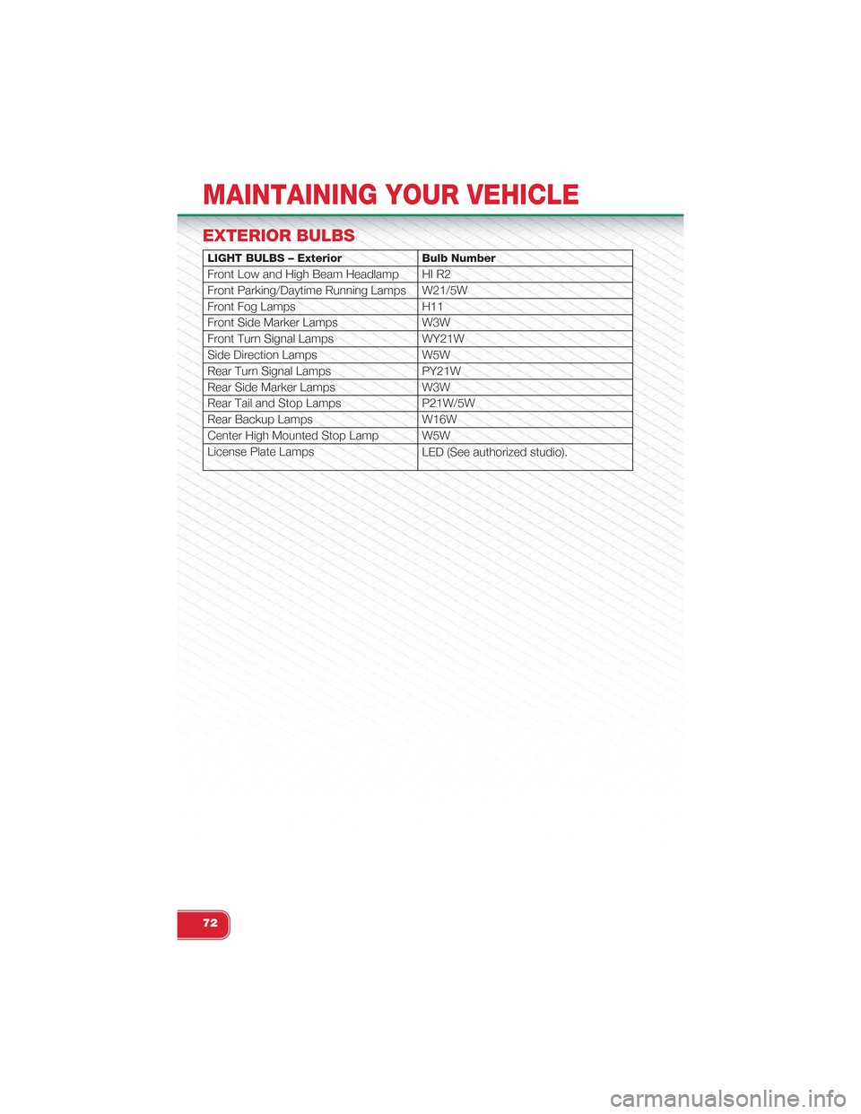
EXTERIOR BULBS
LIGHT BULBS – Exterior Bulb Number
Front Low and High Beam Headlamp HI R2
Front Parking/Daytime Running Lamps W21/5W
Front Fog Lamps H11
Front Side Marker Lamps W3W
Front Turn Signal Lamps WY21W
Side Direction Lamps W5W
Rear Turn Signal Lamps PY21W
Rear Side Marker Lamps W3W
Rear Tail and Stop Lamps P21W/5W
Rear Backup Lamps W16W
Center High Mounted Stop Lamp W5W
License Plate LampsLED (See authorized studio).
MAINTAINING YOUR VEHICLE
72