FIAT 500C 2015 2.G Owners Manual
Manufacturer: FIAT, Model Year: 2015, Model line: 500C, Model: FIAT 500C 2015 2.GPages: 438, PDF Size: 2.96 MB
Page 151 of 438
14. Brake Warning LightThis light monitors various brake functions,
including brake fluid level and parking brake
application. If the brake light turns on it may
indicate that the parking brake is applied, that
the brake fluid level is low, or that there is a problem with
the Anti-lock Brake System reservoir.
If the light remains on when the parking brake has been
disengaged, and the fluid level is at the full mark on the
master cylinder reservoir, it indicates a possible brake
hydraulic system malfunction or that a problem with the
Brake Booster has been detected by the Anti-Lock Brake
System (ABS) / Electronic Stability Control (ESC) system.
In this case, the light will remain on until the condition
has been corrected. If the problem is related to the brake
booster, the ABS pump will run when applying the brake
and a brake pedal pulsation may be felt during each stop. The dual brake system provides a reserve braking capac-
ity in the event of a failure to a portion of the hydraulic
system. A leak in either half of the dual brake system is
indicated by the Brake Warning Light, which will turn on
when the brake fluid level in the master cylinder has
dropped below a specified level.
The light will remain on until the cause is corrected.
NOTE:
The light may flash momentarily during sharp
cornering maneuvers, which change fluid level condi-
tions. The vehicle should have service performed, and
the brake fluid level checked.
If brake failure is indicated, immediate repair is neces-
sary.
4
UNDERSTANDING YOUR INSTRUMENT PANEL 149
Page 152 of 438
WARNING!
Driving a vehicle with the red brake light on is
dangerous. Part of the brake system may have failed.
It will take longer to stop the vehicle. You could have
a collision. Have the vehicle checked immediately.
Vehicles equipped with the ABS, are also equipped with
Electronic Brake Force Distribution (EBD). In the event of
an EBD failure, the Brake Warning Light will turn on
along with the ABS Light. Immediate repair to the ABS
system is required.
Operation of the Brake Warning Light can be checked by
turning the ignition switch from the OFF position to the
ON/RUN position. The light should illuminate for ap-
proximately two seconds. The light should then turn off
unless the parking brake is applied or a brake fault is
detected. If the light does not illuminate, have the light
inspected by an authorized dealer. The light also will turn on when the parking brake is
applied with the ignition switch in the ON/RUN posi-
tion.
NOTE:
This light shows only that the parking brake is
applied. It does not show the degree of brake application.
15. Anti-Lock Brake (ABS) Light
This light monitors the Anti-lock Brake System
(ABS). The light will turn on when the ignition
switch is turned to the ON/RUN position and
may stay on for as long as four seconds.
If the ABS light remains on or turns on while driving, it
indicates that the anti-lock portion of the brake system is
not functioning and that service is required. However,
the conventional brake system will continue to operate
normally if the BRAKE warning light is not on.
If the ABS light is on, the brake system should be serviced
as soon as possible to restore the benefits of anti-lock
150 UNDERSTANDING YOUR INSTRUMENT PANEL
Page 153 of 438
brakes. If the ABS light does not turn on when the
ignition switch is turned to the ON/RUN position, have
the light inspected by an authorized dealer.
16. Gas Pedal Percentage Gauge/Turbo Gauge/ECO In-
dex Gauge
Depending on what options and trim level, your vehicle
is equipped with there are three gauges available.•Gas Pedal Percentage Gauge: This gauge shows
what percent the gas pedal is currently depressed at.
• Turbo Gauge: This gauge shows the current turbo
usage.
• ECO Index Gauge: The ECO Index gauge allows the
driver to monitor their driving style in order to
increase fuel economy. The efficiency of the driving
style is displayed on a gauge located on the right
side of the instrument cluster and ranges from a
minimum value of 0 up to a maximum value of 5 (0
= low, 5 = high). A higher “ECO” index indicates a more fuel efficient drive style and will increase your
fuel economy. A lower “ECO” index indicates fre-
quent accelerations/decelerations and will decrease
your fuel economy. The index is recalculated ap-
proximately every second and takes into account a
combination of the instant fuel economy and your
driving style during the current trip.
NOTE: Different trips may have different values even if
the same driving style is maintained. Some factors that
may impact the calculated index value are:
•Traffic conditions
• Trip duration
• Temperature (engine and ambient)
17. Fuel Gauge
Shows level of fuel in tank when ignition switch is in the
ON/RUN position.
4
UNDERSTANDING YOUR INSTRUMENT PANEL 151
Page 154 of 438
18. Electronic Vehicle Information Center (EVIC)
The EVIC features a driver-interactive display that is
located in the instrument cluster. For further information,
refer to “Electronic Vehicle Information Center (EVIC)” in
“Understanding Your Instrument Panel.”
19. Temperature Gauge
The temperature gauge shows engine coolant tempera-
ture. Any reading within the normal range indicates that
the engine cooling system is operating satisfactorily.
The gauge pointer will likely indicate a higher tempera-
ture when driving in hot weather, up mountain grades,
or when towing a trailer. It should not be allowed to
exceed the upper limits of the normal operating range.CAUTION!
Driving with a hot engine cooling system could
damage your vehicle. If the temperature gauge reads
“H” pull over and stop the vehicle. Idle the vehicle
with the air conditioner turned off until the pointer
drops back into the normal range. If the pointer
remains on the “H” and you hear continuous chimes,
turn the engine off immediately and call an autho-
rized dealer for service.
WARNING!
A hot engine cooling system is dangerous. You or
others could be badly burned by steam or boiling
coolant. You may want to call an authorized dealer
for service if your vehicle overheats. If you decide to
look under the hood yourself, see “Maintaining Your
(Continued)
152 UNDERSTANDING YOUR INSTRUMENT PANEL
Page 155 of 438
WARNING!(Continued)
Vehicle.” Follow the warnings under the “Cooling
System Pressure Cap” paragraph.
20. Tachometer
The tachometer indicates engine speed in Revolutions
Per Minute (RPM x 1000).
21. Speedometer / Trip Odometer / Electronic Vehicle
Information Center (EVIC) Display Area
This display indicates the total distance the vehicle has
been driven.
U.S. Federal regulations require that upon transfer of
vehicle ownership, the seller certify to the purchaser the
correct mileage that the vehicle has been driven. If your
odometer needs to be repaired or serviced, the repair
technician should leave the odometer reading the same
as it was before the repair or service. If s/he cannot do so, then the odometer must be set at zero, and a sticker must
be placed in the door jamb stating what the mileage was
before the repair or service. It is a good idea for you to
make a record of the odometer reading before the repair/
service, so that you can be sure that it is properly reset, or
that the door jamb sticker is accurate if the odometer
must be reset at zero.
NOTE:
If the vehicle is equipped with the Electronic
Vehicle Information Center (EVIC) in the instrument
cluster, all warnings including “door” and “gate” and
“Change Engine Oil” will only be displayed in the EVIC
display. Refer to “Electronic Vehicle Information Center
(EVIC) in “Understanding Your Instrument Panel.”
22. Low Fuel Light
When the fuel level reaches approximately 1.0
gallon (3.8L), this light will turn on, and remain
on until fuel is added.
4
UNDERSTANDING YOUR INSTRUMENT PANEL 153
Page 156 of 438
23. Generic Warning LightThe Generic Warning Light will illuminate if
any of the following conditions occur: Oil
Change Request, Engine Oil Pressure Sensor
Failure, External Light Failure, Fuel Cut-Off
Intervention, Fuel Cut-Off Not Available, Parking Sensor
Failure.
24. Cruise On Indicator — If Equipped
This light will turn on when the electronic
speed control is ON. For further information,
refer to “Electronic Speed Control” in “Under-
standing Your Instrument Panel.”
25. Charging System Light
This light shows the status of the electrical charg-
ing system. The light should come on when the
ignition switch is first turned to ON/RUN and remain on
briefly as a bulb check. If the light stays on or comes on while driving, turn off some of the vehicle’s non-essential
electrical devices or increase engine speed (if at idle). If
the charging system light remains on, it means that the
vehicle is experiencing a problem with the charging
system. Obtain SERVICE IMMEDIATELY. See an autho-
rized dealer.
If jump starting is required, refer to “Jump Starting
Procedures” in “What To Do In Emergencies.”
26. Electronic Throttle Control (ETC) Light
This light informs you of a problem with the
Electronic Throttle Control (ETC) system. If a
problem is detected, the light will come on
while the engine is running. Cycle the ignition
key when the vehicle has completely stopped and the
shift lever is placed in the NEUTRAL position. The light
should turn off. If the light remains lit with the engine
running, your vehicle will usually be drivable. However,
see an authorized dealer for service as soon as possible. If
154 UNDERSTANDING YOUR INSTRUMENT PANEL
Page 157 of 438
the light is flashing when the engine is running, imme-
diate service is required and you may experience reduced
performance, an elevated/rough idle or engine stall and
your vehicle may require towing. The light will come on
when the ignition is first turned to ON/RUN and remain
on briefly as a bulb check. If the light does not come on
during starting, have the system checked by an autho-
rized dealer.
27. Oil Pressure Warning LightThis light indicates low engine oil pressure. The
light should turn on momentarily when the engine is
started. If the light turns on while driving, stop the
vehicle and shut off the engine as soon as possible. A
chime will sound for four minutes when this light turns
on.
Do not operate the vehicle until the cause is corrected.
This light does not indicate how much oil is in the engine.
The engine oil level must be checked under the hood. 28. Engine Temperature Warning Light
This light warns of an overheated engine condi-
tion. The engine coolant temperature indicator
will illuminate and a single chime will sound after
reaching a set threshold.
If the light turns on while driving, safely pull over and
stop the vehicle. If the A/C system is on, turn it off. Also,
shift the transmission into NEUTRAL and idle the ve-
hicle. If the temperature reading does not return to
normal, turn the engine off immediately and call for
service. Refer to “If Your Engine Overheats” in “What To
Do In Emergencies” for further information.
ELECTRONIC VEHICLE INFORMATION CENTER
(EVIC)
The Electronic Vehicle Information Center (EVIC) fea-
tures a driver-interactive display that is located in the
instrument cluster.
4
UNDERSTANDING YOUR INSTRUMENT PANEL 155
Page 158 of 438
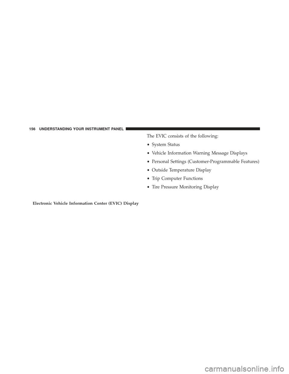
The EVIC consists of the following:
•System Status
• Vehicle Information Warning Message Displays
• Personal Settings (Customer-Programmable Features)
• Outside Temperature Display
• Trip Computer Functions
• Tire Pressure Monitoring Display
Electronic Vehicle Information Center (EVIC) Display
156 UNDERSTANDING YOUR INSTRUMENT PANEL
Page 159 of 438
EVIC Displays
1. Red Telltales (Left Bank)•Hood Ajar
• Low Oil Pressure
• Electronic Throttle Control •
Door Ajar
• Speed Limiter — If Equipped
2. Amber Telltales •Ice Risk
• Fuel Cut Off
• Fuel Cut Off Failed
• Hill Holder Failed
• Oil Change Request
• Check Lights
• Vehicle Lock
3. Electronic Speed Control Active
4. Amber Telltales •Generic Warning Light
• Glow Plug Light
• Park Sensor Failed
• Stop Lamp Failed
Instrument Cluster
4
UNDERSTANDING YOUR INSTRUMENT PANEL 157
Page 160 of 438
5. Red Telltales (Right Bank)•Trunk Ajar
• Transmission Failure
• Battery Charge Indicator
6. Exceeded Speed Limiter
7. Shift Up or Down Indicators
8. Gear Indicator
EVIC Control Buttons
Push and release the MENUbutton briefly to access the
EVIC. Push and hold the MENUbutton (approximately
one second) to return to the main screen.
Push and release the UP
button to scroll upward
through the displayed menu and the related options
or to increase the displayed value.
Push and release the DOWNbutton to scroll down-
ward through the displayed menu and the related
options or to decrease the value displayed.
NOTE: UPand DOWNbuttons activate differ-
ent functions according to the following situations:
• To scroll the menu options upwards or downwards.
• To increase or decrease values during settings.
NOTE: When opening one of the front doors, the EVIC
display will turn on the clock and the miles or kilometers
covered (for versions/markets, where provided) for a
few seconds.
158 UNDERSTANDING YOUR INSTRUMENT PANEL