FIAT 500E 2014 2.G Workshop Manual
Manufacturer: FIAT, Model Year: 2014, Model line: 500E, Model: FIAT 500E 2014 2.GPages: 92, PDF Size: 3.24 MB
Page 51 of 92
•On your mobile phone, search for devices equipped with Bluetooth® wireless technol-
ogy (the setting on your mobile phone might be called Discover or New Device).In
this list you will find BLUE&ME™ (name identifying the BLUE&ME™ system on your
car) select it.
•When prompted by the mobile phone, enter the PIN number shown on the instru-
ment panel display using your mobile phone keypad.If pairing is successful, the system
will say “Connecting” and at the end the display will show as confirmation message, the
ID of the paired mobile phone.
•It is essential to wait until you see this confirmation message on the display.Pressing
PHONE/MENU button on the steering wheel or MUTE/ESC button before the mes-
sage is displayed may cancel the pairing process.If the pairing process fails, an error
message will be displayed: in this event repeat the pairing procedure.
•At first pairing, BLUE&ME™ will say “Welcome” immediately after connecting.This
message will no longer be heard when your phone automatically connects to the
BLUE&ME™ system on future ignition cycles.
•BLUE&ME™ will ask if you would like to copy your paired phone phonebook to
BLUE&ME™.It is recommended to copy it.To start copying the phonebook say “Yes,”
otherwise say “No.”
•For certain mobile phones the phonebook is not copied automatically, in this case you
must transfer the phonebook contacts using your mobile phone keypad.If
BLUE&ME™ asks you to do this, then perform this procedure following the instruc-
tions specific to your mobile phone and press the PHONE/MENU button on the
steering wheel when you have finished.Certain mobile phones may require you to
indicate that you do not want to be asked every time to copy the phonebook.If this is
the case, this could be indicated by checking a box on the phone during the pairing
process.If applicable, this option will only be presented on the phone during the pair-
ing process.
Making A Phone Call
•Assume that “John Smith” is one of the contacts stored in your phonebook.To call
John Smith, proceed as follows:
1.Press the VR steering wheel button and pronounce “Call John Smith.” If the name is
recognized, the system will display the recognized contact’s information on the display
screen.
2.If there is just one phone number for John Smith in your phonebook, the system will
ask if you would like to call John Smith.To start the call say “Yes,” otherwise say “No.”
If John Smith has several phone numbers, the system will ask which phone number
you would like to call (e.g.: “Call John Smith (at) Work or (at) Home?”).Answer with
the type of required phone number (e.g.: “(at) Home”).
ELECTRONICS
49
Page 52 of 92
3.If John Smith has several phone numbers but the “location” (e.g.: the type of phone
number like work, home, etc.) is missing, the system will display the selected contact
and a list of related phone numbers on the instrument cluster display.The hands-free
phone system will ask if you would like to call the phone number displayed.To r e -
spond with “Yes,” pronounce “Yes,” otherwise say “No.” If this is the correct contact
but the wrong number, say “Forward” or “Backward” to navigate to the phone num-
ber you’d like to call.To call the displayed phone number, pronounce “Call.” You can
also scroll through the phone number list manually by pressing the buttons on the
back of the steering wheel until you find the required number.Then, press PRESET
UP/OK button on the rear of the steering wheel to start the call.
4.To end the phone call, press the PHONE HANG UP button on the steering wheel.
Media Player
•With the BLUE&ME™ media player you can play, via the car sound system, the digital
audio files stored on a USB device by simply connecting it to the USB port located in
the glove compartment of the car.
•The MEDIA PLAYER menu enables the following:
– Display tracks stored on your USB stick/iPod®.
– Play audio files stored on your USB stick/iPod® (BLUE&ME™ recognizes.wma,.mp3
and.wav,.aac formats for audio files and.wpl and.m3u for playlists).
How To Connect The USB Stick/iPod® To BLUE&ME™
•To connect your USB stick/iPod® to BLUE&ME™, proceed as follows:
•USB devices without USB wire: just connect the USB stick/iPod® (directly or by an
extension lead) to the USB port on the car.
•USB stick/iPod® with USB wire: use the wire to connect the USB stick/iPod® to
the USB port on the car.
•Turn the ignition key to ON.BLUE&ME™ will start automatically to play your digital
tracks selecting them from the library built at the moment the USB stick/iPod® is
connected.
•If AUTOPLAY is set to “ON,” BLUE&ME™ will start playback automatically.
•Refer to the iPod®/USB/MP3 CONTROL section in this manual and the BLUE&ME™
User's Manual on the DVD for more details.
WARNING!
Driving while distracted can result in loss of vehicle control, accident and injury.It is
strongly recommended that you use extreme caution when using any device or feature
that may take your focus off the road or your hands off the steering wheel.Your pri-
mary responsibility is the safe operation of your vehicle.
ELECTRONICS
50
Page 53 of 92
iPod®/USB/MP3 CONTROL
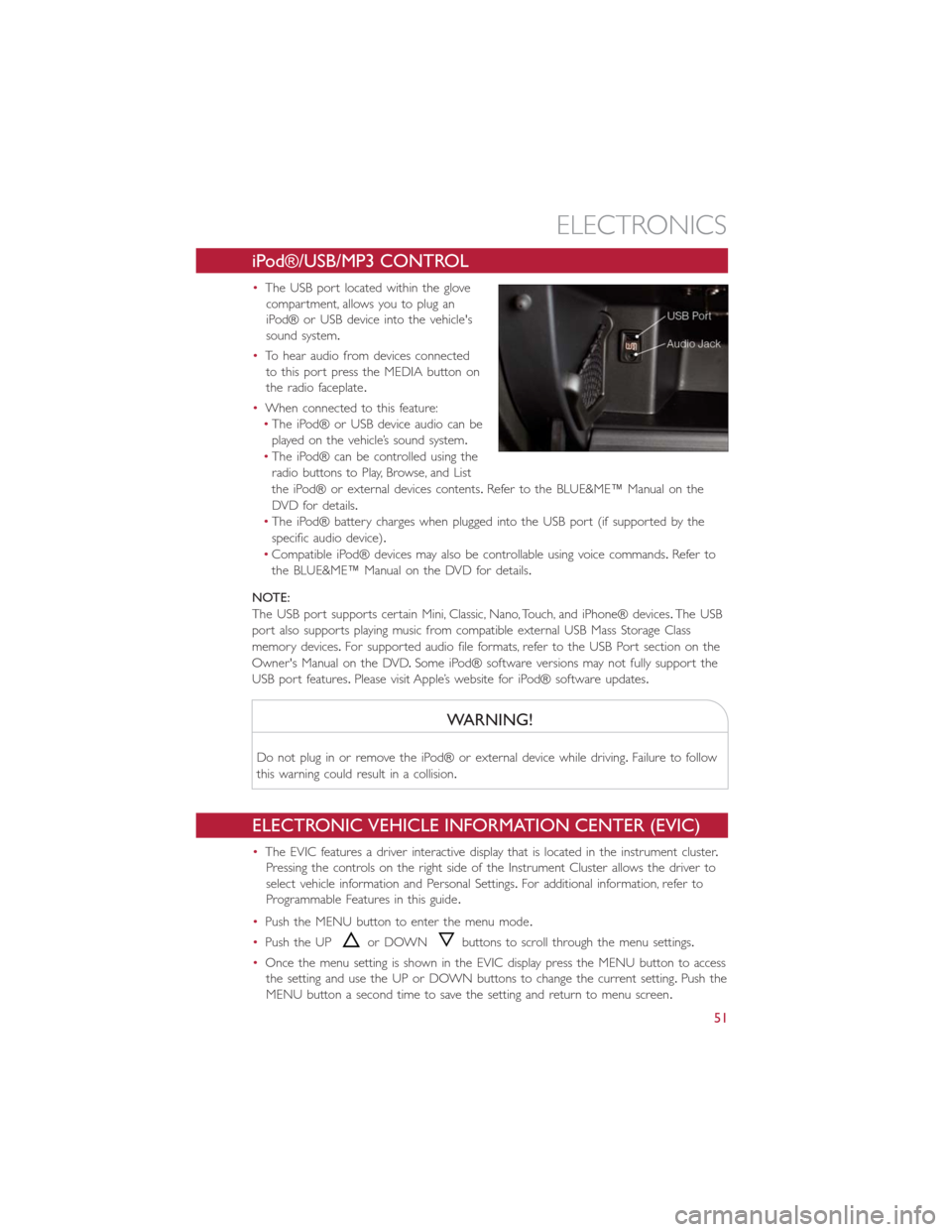
•The USB port located within the glove
compartment, allows you to plug an
iPod® or USB device into the vehicle's
sound system.
•To hear audio from devices connected
to this port press the MEDIA button on
the radio faceplate.
•When connected to this feature:
•The iPod® or USB device audio can be
played on the vehicle’s sound system.
•The iPod® can be controlled using the
radio buttons to Play, Browse, and List
the iPod® or external devices contents.Refer to the BLUE&ME™ Manual on the
DVD for details.
•The iPod® battery charges when plugged into the USB port (if supported by the
specific audio device).
•Compatible iPod® devices may also be controllable using voice commands.Refer to
the BLUE&ME™ Manual on the DVD for details.
NOTE:
The USB port supports certain Mini, Classic, Nano, Touch, and iPhone® devices.The USB
port also supports playing music from compatible external USB Mass Storage Class
memory devices.For supported audio file formats, refer to the USB Port section on the
Owner's Manual on the DVD.Some iPod® software versions may not fully support the
USB port features.Please visit Apple’s website for iPod® software updates.
WARNING!
Do not plug in or remove the iPod® or external device while driving.Failure to follow
this warning could result in a collision.
ELECTRONIC VEHICLE INFORMATION CENTER (EVIC)
•The EVIC features a driver interactive display that is located in the instrument cluster.
Pressing the controls on the right side of the Instrument Cluster allows the driver to
select vehicle information and Personal Settings.For additional information, refer to
Programmable Features in this guide.
•Push the MENU button to enter the menu mode.
•Push the UP
or DOWNbuttons to scroll through the menu settings.
•Once the menu setting is shown in the EVIC display press the MENU button to access
the setting and use the UP or DOWN buttons to change the current setting.Push the
MENU button a second time to save the setting and return to menu screen.
ELECTRONICS
51
Page 54 of 92
PROGRAMMABLE FEATURES
Electronic Vehicle Information Center (EVIC)
•Push the MENU button to enter the menu mode.
•Push the UP
or DOWNbuttons to scroll through the menu settings.
•Once the menu setting is shown in the EVIC display press the MENU button to access
the setting and use the UP or DOWN buttons to change the current setting.Push the
MENU button a second time to save the setting and return to menu screen.
•Charging Schedule•Daytime Running Lights
•Set Date•Button Volume
•Set Time•Hill Start Assist
•Units•Stored Warning
•Languages•Tutorial
•Audio Display•Connectivity ID
•Battery % Display•Restore Factory Settings
•Auto Door Lock•Exit Menu
•Remote Unlock
Selecting An Option Of The Main Menu Without Submenu:
•Briefly push the MENU button to select the main menu option to set.
•Push the UP or DOWN button to select the new setting.
•Briefly press the MENU button to store the new setting and go back to the main
menu option previously selected.
Selecting An Option Of The Main Menu With Submenu:
•Briefly push the MENU button to display the first submenu option.
•Push the UP or DOWN button to scroll through all the submenu options.
•Briefly press the MENU button to select the displayed submenu option and to open
the relevant setup menu.
•Push the UP or DOWN button to select the new setting for this submenu option.
•Briefly press the MENU button to store the new setting and go back to the previously
selected submenu option.
•Push and hold the MENU button to return to the main menu (short hold) or the
main screen (longer hold).
NOTE:
The charging schedule is based on the date and time programmed in the EVIC.
ELECTRONICS
52
Page 55 of 92
TRIP BUTTON
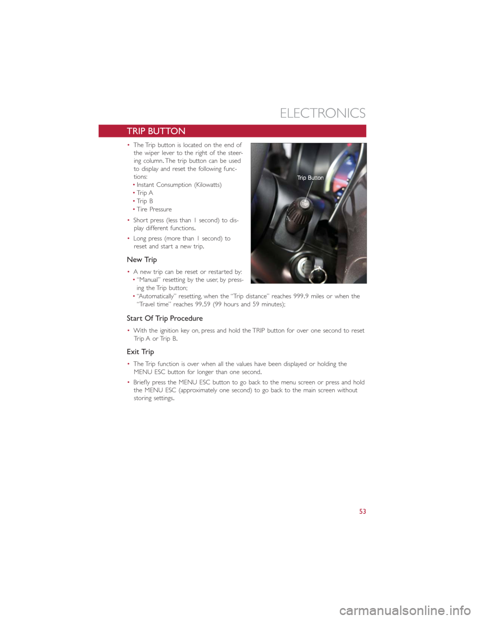
•The Trip button is located on the end of
the wiper lever to the right of the steer-
ing column.The trip button can be used
to display and reset the following func-
tions:
•Instant Consumption (Kilowatts)
•Trip A
•Trip B
•Tire Pressure
•Short press (less than 1 second) to dis-
play different functions.
•Long press (more than 1 second) to
reset and start a new trip.
New Trip
•A new trip can be reset or restarted by:
•“Manual” resetting by the user, by press-
ing the Trip button;
•“Automatically” resetting, when the “Trip distance” reaches 999.9 miles or when the
“Travel time” reaches 99.59 (99 hours and 59 minutes);
Start Of Trip Procedure
•With the ignition key on, press and hold the TRIP button for over one second to reset
Trip A or Trip B.
Exit Trip
•The Trip function is over when all the values have been displayed or holding the
MENU ESC button for longer than one second.
•Briefly press the MENU ESC button to go back to the menu screen or press and hold
the MENU ESC (approximately one second) to go back to the main screen without
storing settings.
ELECTRONICS
53
Page 56 of 92
POWER OUTLET
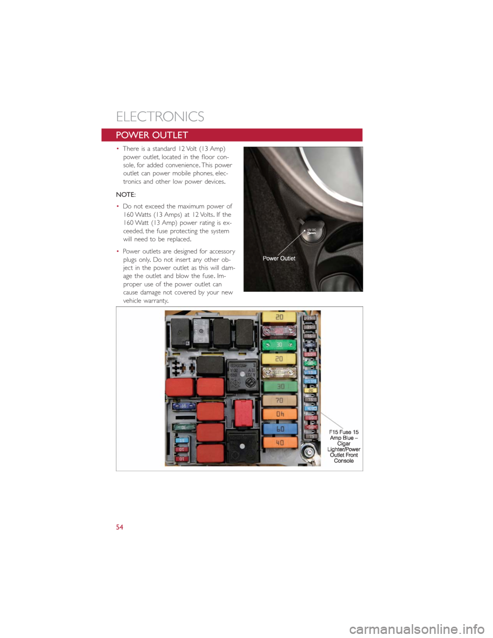
•There is a standard 12 Volt (13 Amp)
power outlet, located in the floor con-
sole, for added convenience.This power
outlet can power mobile phones, elec-
tronics and other low power devices.
NOTE:
•Do not exceed the maximum power of
160 Watts (13 Amps) at 12 Volts.If the
160 Watt (13 Amp) power rating is ex-
ceeded, the fuse protecting the system
will need to be replaced.
•Power outlets are designed for accessory
plugs only.Do not insert any other ob-
ject in the power outlet as this will dam-
age the outlet and blow the fuse.Im-
proper use of the power outlet can
cause damage not covered by your new
vehicle warranty.
ELECTRONICS
54
Page 57 of 92
TRAILER TOWING WEIGHTS (MAXIMUM TRAILER
WEIGHT RATINGS)
•Trailer towing with this vehicle is not recommended.
RECREATIONAL TOWING (BEHIND MOTORHOME, ETC.)
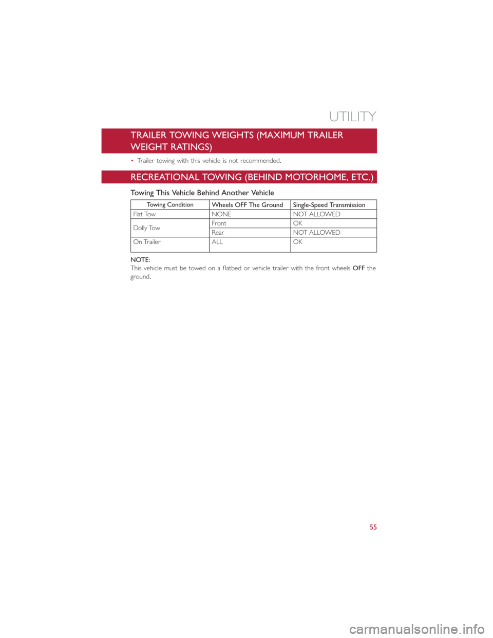
Towing This Vehicle Behind Another Vehicle
Towing ConditionWheels OFF The Ground Single-Speed Transmission
Flat Tow NONE NOT ALLOWED
Dolly TowFront OK
Rear NOT ALLOWED
On Trailer ALL OK
NOTE:
This vehicle must be towed on a flatbed or vehicle trailer with the front wheelsOFFthe
ground.
UTILITY
55
Page 58 of 92
24-HOUR ROADSIDE ASSISTANCE
•If your FIAT 500e requires jump start assistance, tire service, lockout service or towing
due to a defect covered under the Basic Limited Warranty, dial toll-free
1-888-242-6342.See your Warranty booklet for further details.
•Provide your name, vehicle identification number and license plate number.
•Provide your location, including telephone number, from which you are calling.
•Briefly describe the nature of the problem and answer a few simple questions.
•You will be given the name of the service provider and an estimated time of arrival.If
you feel you are in an “unsafe situation”, please let us know.With your consent, we will
contact local police or safety authorities.
INSTRUMENT CLUSTER WARNING LIGHTS
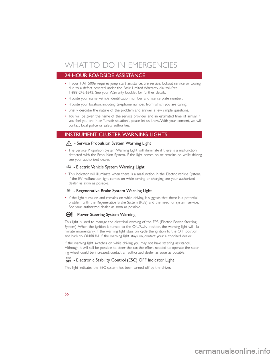
- Service Propulsion System Warning Light
•The Service Propulsion System Warning Light will illuminate if there is a malfunction
detected with the Propulsion System.If the light comes on or remains on while driving
see your authorized dealer.
- Electric Vehicle System Warning Light
•This indicator will illuminate when there is a malfunction in the Electric Vehicle System.
If the EV malfunction light comes on while driving or charging see your authorized
dealer as soon as possible.
- Regenerative Brake System Warning Light
•If the light turns on and remains on while driving, it suggests that there is a potential
problem with the Regenerative Brake System (RBS) and the need for system service.
See your authorized dealer as soon as possible.
- Power Steering System Warning
This light is used to manage the electrical warning of the EPS (Electric Power Steering
System).When the ignition is turned to the ON/RUN position, the warning light will illu-
minate momentarily.If the warning light stays on, cycle the ignition to the OFF position
and back to ON/RUN.If the warning light stays on, contact your authorized dealer.
If the warning light switches on while driving you may not have steering assistance.
Although it will still be possible to steer the car, the effort needed to operate the steer-
ing wheel could be increased: contact an authorized dealer as soon as possible.
- Electronic Stability Control (ESC) OFF Indicator Light
This light indicates the ESC system has been turned off by the driver.
WHAT TO DO IN EMERGENCIES
56
Page 59 of 92
Partial Off
This mode is entered by momentarily pressing the ESC Off switch.This mode is intended
for times when a more spirited driving experience is desired.It is also intended for driv-
ing in deep snow, sand or gravel conditions, when more wheel spin than ESC would nor-
mally allow is required to gain traction.To turn ESC on again, momentarily press the
switch again.This will restore the normal ESC On mode of operation.
Full Off
This mode is intended for off-highway or off-road use only and should not be used on
public roadways.In this mode, all TCS and ESC stability features are turned OFF, except
for the limited slip feature described in the TCS section.To enter the “Full Off ” mode,
depress and hold the ESC OFF switch for five seconds.After five seconds, the ESC OFF
Indicator Light will illuminate, and the “ESC OFF” message will display in the EVIC.To turn
ESC ON again, momentarily press the ESC OFF switch.
- Electronic Stability Control (ESC) Activation / Malfunction
Indicator Light
The “ESC Activation/Malfunction Indicator Light” in the instrument cluster will come on
for four seconds when the ignition switch is turned to the ON/RUN position.If the “ESC
Activation/Malfunction Indicator Light” comes on continuously with the engine running, a
malfunction has been detected in the ESC system.If this light remains on, see your
authorized dealer as soon as possible to have the problem diagnosed and corrected.
NOTE:
•The “ESC Off Indicator Light” and the “ESC Activation/Malfunction Indicator Light”
come on momentarily each time the ignition switch is turned to ON/RUN.
•Each time the ignition is turned to ON/RUN, the ESC system will be ON even if it
was turned off previously.
•ESC Activation/Malfunction Light can blink during a ESC or TC intervention.
- Tire Pressure Monitoring System (TPMS) Light
•Each tire, including the spare (if provided), should be checked monthly when cold and
inflated to the inflation pressure recommended by the vehicle manufacturer on the
vehicle placard or tire inflation pressure label.(If your vehicle has tires of a different
size than the size indicated on the vehicle placard or tire inflation pressure label, you
should determine the proper tire inflation pressure for those tires.)
•As an added safety feature, your vehicle has been equipped with a Tire Pressure Moni-
toring System (TPMS) that illuminates a low tire pressure telltale when one or more
of your tires is significantly under-inflated.Accordingly, when the low tire pressure tell-
tale illuminates, you should stop and check your tires as soon as possible, and inflate
them to the proper pressure.Driving on a significantly under-inflated tire causes the
tire to overheat and can lead to tire failure.Under-inflation also reduces fuel efficiency
and tire tread life, and may affect the vehicle’s handling and stopping ability.
WHAT TO DO IN EMERGENCIES
57
Page 60 of 92
•IF THE LIGHT STARTS FLASHING INDICATING A LOW TIRE PRESSURE, ADJUST
THE AIR PRESSURE IN THE LOW TIRE TO THE AIR PRESSURE SHOWN ON THE
VEHICLE PLACARD OR TIRE INFLATION PRESSURE LABEL LOCATED ON THE
DRIVER'S DOOR.
NOTE:
After inflation, the vehicle may need to be driven for 20 minutes before the flashing light
will turn off.
•Please note that the TPMS is not a substitute for proper tire maintenance, and it is the
driver’s responsibility to maintain correct tire pressure, even if under-inflation has not
reached the level to trigger illumination of the TPMS low tire pressure telltale.
•Your vehicle has also been equipped with a TPMS malfunction indicator to indicate
when the system is not operating properly.The TPMS malfunction indicator is com-
bined with the low tire pressure telltale.When the system detects a malfunction, the
telltale will flash for approximately one minute and then remain continuously illumi-
nated.This sequence will continue upon subsequent vehicle start-ups as long as the
malfunction exists.
•When the malfunction indicator is illuminated, the system may not be able to detect
or signal low tire pressure as intended.TPMS malfunctions may occur for a variety of
reasons, including the installation of replacement or alternate tires or wheels on the
vehicle that prevent the TPMS from functioning properly.Always check the TPMS mal-
function telltale after replacing one or more tires or wheels on your vehicle, to ensure
that the replacement or alternate tires and wheels allow the TPMS to continue to
function properly.
NOTE:
Tire pressures change by approximately 1 psi (7 kPa) per 12° F (7° C) of air tempera-
ture change.Keep this in mind when checking tire pressure inside a garage, especially in
the Winter.Example: If garage temperature is 68°F (20°C) and the outside temperature
is 32°F (0°C), then the cold tire inflation pressure should be increased by 3 psi (21 kPa),
which equals 1 psi (7 kPa) for every 12°F (7°C) for this outside temperature condition.
CAUTION!
The TPMS has been optimized for the original equipment tires and wheels.TPMS pres-
sures and warning have been established for the tire size equipped on your vehicle.
Undesirable system operation or sensor damage may result when using replacement
equipment that is not of the same size, type, and/or style.Aftermarket wheels can cause
sensor damage.Do not use tire sealant from a can, or balance beads if your vehicle is
equipped with a TPMS, as damage to the sensors may result.
WHAT TO DO IN EMERGENCIES
58