air FIAT 500E 2016 2.G Owner's Guide
[x] Cancel search | Manufacturer: FIAT, Model Year: 2016, Model line: 500E, Model: FIAT 500E 2016 2.GPages: 132, PDF Size: 4.59 MB
Page 95 of 132
If the sealant (white fluid) does not flow within0–10seconds through the Sealant
Hose (6):
1.Push the Power Button (4) to turn Off the Tire Service Kit.Disconnect the Sealant
Hose (6) from the valve stem.Make sure the valve stem is free of debris.Reconnect
the Sealant Hose (6) to the valve stem.Check that the Mode Select Knob (5) is in
the Sealant Mode position and not Air Mode.Push the Power Button (4) to turn On
the Tire Service Kit.
2.Connect the Power Plug (8) to a different 12 Volt power outlet in your vehicle or
another vehicle, if available.Make sure the engine is running before turning ON the
Tire Service Kit.
3.The Sealant Bottle (1) may be empty due to previous use.Call for assistance.
NOTE:
If the Mode Select Knob (5) is on Air Mode and the pump is operating, air will dispense
from the Air Pump Hose (7) only, not the Sealant Hose (6).
If the sealant (white fluid) does flow through the Sealant Hose (6):
1.Continue to operate the pump until sealant is no longer flowing through hose (typi-
cally takes 30 - 70 seconds).As the sealant flows through the Sealant Hose (6), the
Pressure Gauge (3) can read as high as 70 psi (4.8 Bar).The Pressure Gauge (3) will
decrease quickly from approximately 70 psi (4.8 Bar) to the actual tire pressure when
the Sealant Bottle (1) is empty.
2.The pump will start to inject air into the tire immediately after the Sealant Bottle (1)
is empty.Continue to operate the pump and inflate the tire to the pressure indicated
on the tire pressure label on the driver-side latch pillar (recommended pressure).
Check the tire pressure by looking at the Pressure Gauge (3).
If the tire does not inflate to at least 26 psi (1.8 Bar) pressure within 15 minutes:
•The tire is too badly damaged.Do not attempt to drive the vehicle further.Call for
assistance.
NOTE:
If the tire becomes over-inflated, push the Deflation Button to reduce the tire pressure
to the recommended inflation pressure before continuing.
If the tire inflates to the recommended pressure or is at least 26 psi (1.8 Bar) pressure
within 15 minutes:
1.Push the Power Button (4) to turn off the Tire Service Kit.
2.Remove the Speed Limit sticker from the top of the Sealant Bottle (1) and place the
sticker on the instrument panel.
3.Immediately disconnect the Sealant Hose (6) from the valve stem, reinstall the cap on
the fitting at the end of the hose, and place the Tire Service Kit in the vehicle storage
location.Quickly proceed to (D) “Drive Vehicle.”
WHAT TO DO IN EMERGENCIES
93
Page 96 of 132
CAUTION!
•The metal end fitting from Power Plug (8) may get hot after use, so it should be
handled carefully.
•Failure to reinstall the cap on the fitting at the end of the Sealant Hose (6) can
result in sealant contacting your skin, clothing, and the vehicle’s interior.It can also
result in sealant contacting internal Tire Service Kit components which may cause
permanent damage to the kit.
(D) Drive Vehicle:
Immediately after injecting sealant and inflating the tire, drive the vehicle 5 miles (8 km)
or 10 minutes to ensure distribution of the Tire Service Kit Sealant within the tire.Do
not exceed 55 mph (90 km/h).
WARNING!
Tire Service Kit is not a permanent flat tire repair.Have the tire inspected and repaired
or replaced after using Tire Service Kit.Do not exceed 55 mph (90 km/h) until the tire
is repaired or replaced.Failure to follow this warning can result in injuries that are seri-
ous or fatal to you, your passengers, and others around you.
(E) After Driving:
Pull over to a safe location.Refer to “Whenever You Stop to Use Tire Service Kit” before
continuing.
1.Push in the Mode Select Knob (5) and turn to the Air Mode position.
2.Uncoil the power plug and insert the plug into the vehicle's 12 Volt power outlet.
3.Uncoil the Air Pump Hose (7) (black in color) and screw the fitting at the end of
hose (7) onto the valve stem.
4.Check the pressure in the tire by reading the Pressure Gauge (3).
If tire pressure is less than 19 psi (1.3 Bar):
The tire is too badly damaged.Do not attempt to drive the vehicle further.Call for assis-
tance.
WHAT TO DO IN EMERGENCIES
94
Page 97 of 132
If the tire pressure is 19 psi (1.3 Bar) or higher:
1.Push the Power Button (4) to turn on Tire Service Kit and inflate the tire to the pres-
sure indicated on the tire and loading information label on the driver-side door open-
ing.
NOTE:
If the tire becomes over-inflated, push the Deflation Button to reduce the tire pressure
to the recommended inflation pressure before continuing.
2.Disconnect the Tire Service Kit from the valve stem, reinstall the cap on the valve
stem and unplug from 12 Volt outlet.
3.Place the Tire Service Kit in its proper storage area in the vehicle.
4.Have the tire inspected and repaired or replaced at the earliest opportunity at an
authorized dealer or tire service center.
5.Remove the Speed Limit sticker from the instrument panel after the tire has been
repaired.
6.Replace the Sealant Bottle (1) and Sealant Hose (6) assembly at your authorized
dealer as soon as possible.Refer to (F) “Sealant Bottle and Hose Replacement”.
NOTE:
When having the tire serviced, advise the authorized dealer or service center that the
tire has been sealed using the Tire Service Kit.
(F) Sealant Bottle And Hose Replacement:
1.Uncoil the Sealant Hose (6) (clear in color).
2.Locate the round Sealant Bottle release button in the recessed area under the sealant
bottle.
3.Push the Sealant Bottle release button.The Sealant Bottle (1) will pop up.Remove the
bottle and dispose of it accordingly.
4.Clean any remaining sealant from the Tire Service Kit housing.
5.Position the new Sealant Bottle (1) in the housing so that the Sealant Hose (6) aligns
with the hose slot in the front of the housing.Push the bottle into the housing.An
audible click will be heard indicating the bottle is locked into place.
6.Verify that the cap is installed on the fitting at the end of the Sealant Hose (6) and
return the hose to its storage area (located on the bottom of the air pump).
7.Return the Tire Service Kit to its storage location in the vehicle.
WHAT TO DO IN EMERGENCIES
95
Page 102 of 132
TOWING A DISABLED VEHICLE
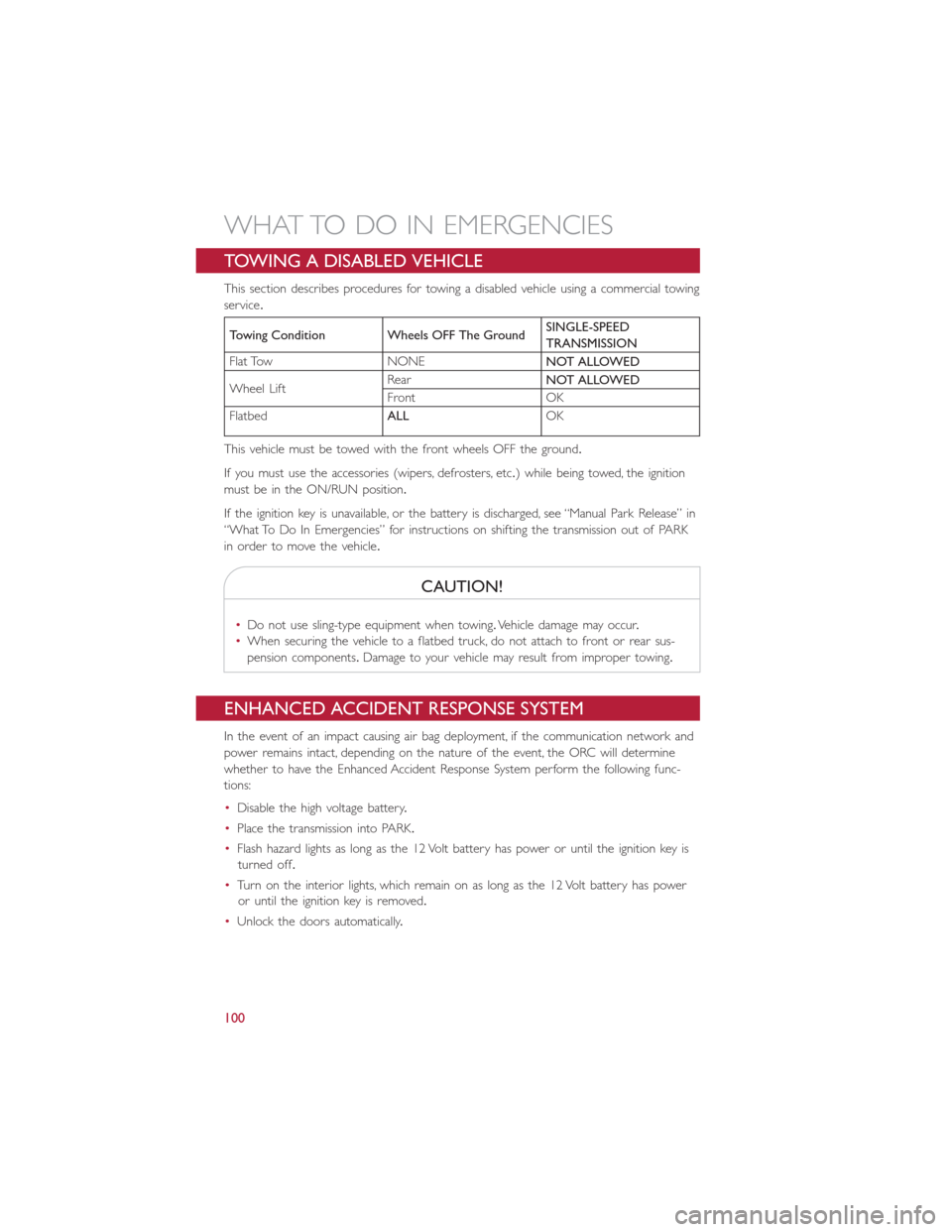
This section describes procedures for towing a disabled vehicle using a commercial towing
service.
Towing Condition Wheels OFF The GroundSINGLE-SPEED
TRANSMISSION
Flat Tow NONE
NOT ALLOWED
Wheel LiftRear
NOT ALLOWED
Front OK
Flatbed
ALLOK
This vehicle must be towed with the front wheels OFF the ground.
If you must use the accessories (wipers, defrosters, etc.) while being towed, the ignition
must be in the ON/RUN position.
If the ignition key is unavailable, or the battery is discharged, see “Manual Park Release” in
“What To Do In Emergencies” for instructions on shifting the transmission out of PARK
in order to move the vehicle.
CAUTION!
•Do not use sling-type equipment when towing.Vehicle damage may occur.
•When securing the vehicle to a flatbed truck, do not attach to front or rear sus-
pension components.Damage to your vehicle may result from improper towing.
ENHANCED ACCIDENT RESPONSE SYSTEM
In the event of an impact causing air bag deployment, if the communication network and
power remains intact, depending on the nature of the event, the ORC will determine
whether to have the Enhanced Accident Response System perform the following func-
tions:
•Disable the high voltage battery.
•Place the transmission into PARK.
•Flash hazard lights as long as the 12 Volt battery has power or until the ignition key is
turned off.
•Turn on the interior lights, which remain on as long as the 12 Volt battery has power
or until the ignition key is removed.
•Unlock the doors automatically.
WHAT TO DO IN EMERGENCIES
100
Page 104 of 132
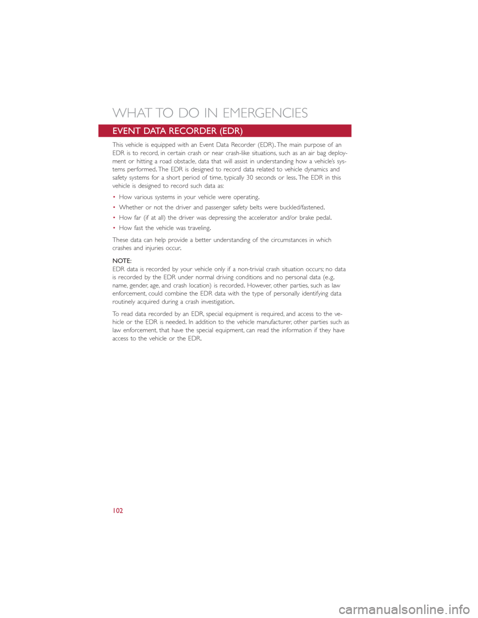
EVENT DATA RECORDER (EDR)
This vehicle is equipped with an Event Data Recorder (EDR).The main purpose of an
EDR is to record, in certain crash or near crash-like situations, such as an air bag deploy-
ment or hitting a road obstacle, data that will assist in understanding how a vehicle’s sys-
tems performed.The EDR is designed to record data related to vehicle dynamics and
safety systems for a short period of time, typically 30 seconds or less.The EDR in this
vehicle is designed to record such data as:
•How various systems in your vehicle were operating.
•Whether or not the driver and passenger safety belts were buckled/fastened.
•How far (if at all) the driver was depressing the accelerator and/or brake pedal.
•How fast the vehicle was traveling.
These data can help provide a better understanding of the circumstances in which
crashes and injuries occur.
NOTE:
EDR data is recorded by your vehicle only if a non-trivial crash situation occurs; no data
is recorded by the EDR under normal driving conditions and no personal data (e.g.
name, gender, age, and crash location) is recorded.However, other parties, such as law
enforcement, could combine the EDR data with the type of personally identifying data
routinely acquired during a crash investigation.
To read data recorded by an EDR, special equipment is required, and access to the ve-
hicle or the EDR is needed.In addition to the vehicle manufacturer, other parties such as
law enforcement, that have the special equipment, can read the information if they have
access to the vehicle or the EDR.
WHAT TO DO IN EMERGENCIES
102
Page 110 of 132
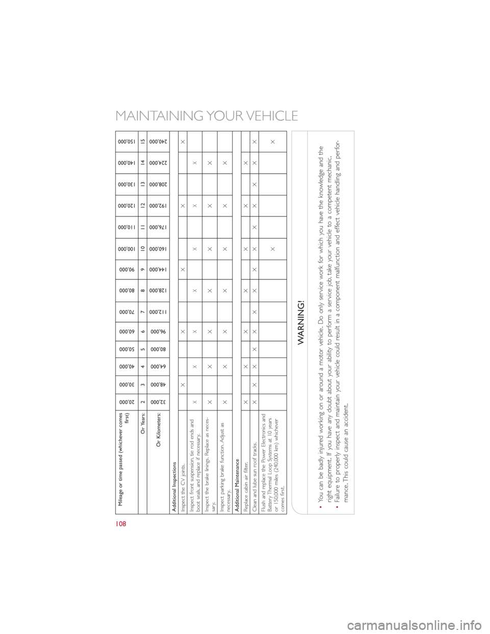
Mileage or time passed (whichever comes
first)
20,000
30,000
40,000
50,000
60,000
70,000
80,000
90,000
100,000
110,000
120,000
130,000
140,000
150,000
Or Years: 2 3 4 5 6 7 8 9 10 11 12 13 14 15
Or Kilometers:
32,000
48,000
64,000
80,000
96,000
112,000
128,000
144,000
160,000
176,000
192,000
208,000
224,000
240,000
Additional Inspections
Inspect the CV joints.XX X X X
Inspect front suspension, tie rod ends and
boot seals, and replace if necessary.
XXX X X X X
Inspect the brake linings.Replace as neces-
sary.XXX X X X X
Inspect parking brake function.Adjust as
necessary.XXX X X X X
Additional Maintenance
Replace cabin air filter.XXX X X X X
Clean and lube sun roof tracks.XX XX X X X X X X X X X X
Flush and replace the Power Electronics and
Battery Thermal Loop Systems at 10 years
or 150,000 miles (240,000 km) whichever
comes first.XX
WARNING!
•You can be badly injured working on or around a motor vehicle.Do only service work for which you have the knowledge and the
right equipment.If you have any doubt about your ability to perform a service job, take your vehicle to a competent mechanic.
•Failure to properly inspect and maintain your vehicle could result in a component malfunction and effect vehicle handling and perfor-
mance.This could cause an accident.
MAINTAINING YOUR VEHICLE
108
Page 112 of 132
FUSES
WARNING!
•When replacing a blown fuse, always use an appropriate replacement fuse with
the same amp rating as the original fuse.Never replace a fuse with another fuse
of higher amp rating.Never replace a blown fuse with metal wires or any other
material.Failure to use proper fuses may result in serious personal injury, fire
and/or property damage.
•Before replacing a fuse, make sure that the ignition is off and that all the other
services are switched off and/or disengaged.
•If the replaced fuse blows again, contact an authorized dealer.
•If a general protection fuse for safety systems (air bag system, braking system),
power unit systems (engine system, gearbox system) or steering system blows,
contact an authorized dealer.
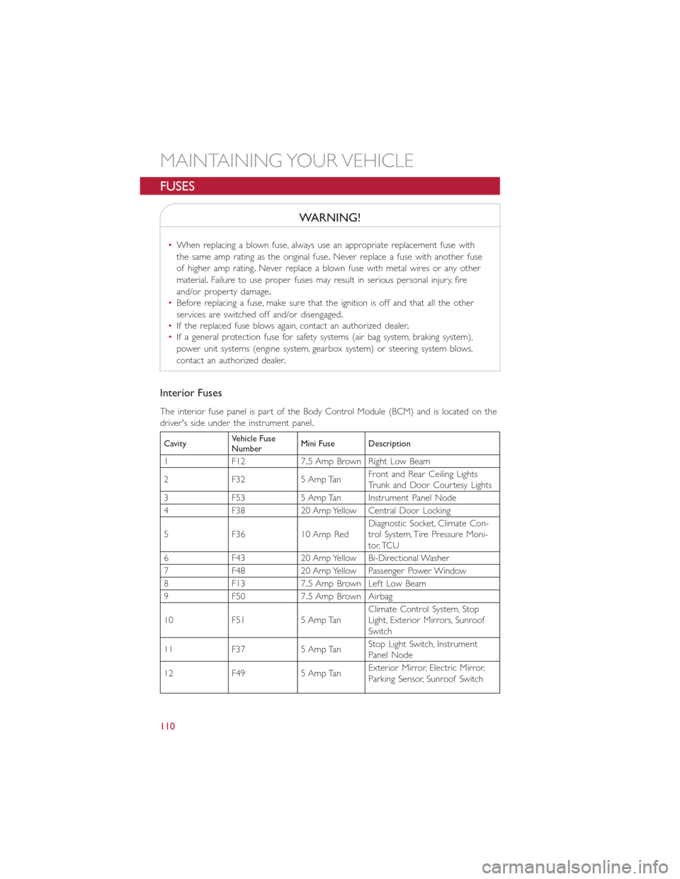
Interior Fuses
The interior fuse panel is part of the Body Control Module (BCM) and is located on the
driver's side under the instrument panel.
CavityVehicle Fuse
NumberMini Fuse Description
1 F12 7.5 Amp Brown Right Low Beam
2 F32 5 Amp TanFront and Rear Ceiling Lights
Trunk and Door Courtesy Lights
3 F53 5 Amp Tan Instrument Panel Node
4 F38 20 Amp Yellow Central Door Locking
5 F36 10 Amp RedDiagnostic Socket, Climate Con-
trol System, Tire Pressure Moni-
tor, TCU
6 F43 20 Amp Yellow Bi-Directional Washer
7 F48 20 Amp Yellow Passenger Power Window
8 F13 7.5 Amp Brown Left Low Beam
9 F50 7.5 Amp Brown Airbag
10 F51 5 Amp TanClimate Control System, Stop
Light, Exterior Mirrors, Sunroof
Switch
11 F37 5 Amp TanStop Light Switch, Instrument
Panel Node
12 F49 5 Amp TanExterior Mirror, Electric Mirror,
Parking Sensor, Sunroof Switch
MAINTAINING YOUR VEHICLE
110
Page 113 of 132
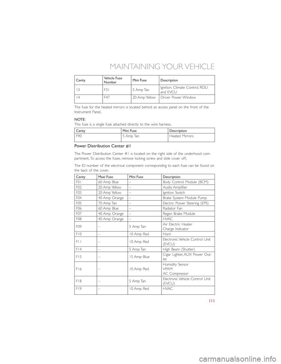
CavityVehicle Fuse
NumberMini Fuse Description
13 F31 5 Amp TanIgnition, Climate Control, RDU
and EVCU
14 F47 20 Amp Yellow Driver Power Window
The fuse for the heated mirrors is located behind an access panel on the front of the
Instrument Panel.
NOTE:
This fuse is a single fuse attached directly to the wire harness.
Cavity Mini Fuse Description
F90 5 Amp Tan Heated Mirrors
Power Distribution Center #1
The Power Distribution Center #1 is located on the right side of the underhood com-
partment.To access the fuses, remove locking screw and slide cover off.
The ID number of the electrical component corresponding to each fuse can be found on
thebackofthecover.
Cavity Maxi Fuse Mini Fuse Description
F01 60 Amp Blue – Body Control Module (BCM)
F02 20 Amp Yellow – Audio Amplifier
F03 20 Amp Yellow – Ignition Switch
F04 40 Amp Orange – Brake System Module Pump
F05 70 Amp Tan – Electric Power Steering (EPS)
F06 60 Amp Blue – Radiator Fan
F07 40 Amp Orange – Regen Brake Module
F08 40 Amp Orange – HVAC
F09 – 5 Amp TanAir Electric Heater
Charge Indicator
F10 – 10 Amp Red Horn
F11 – 10 Amp RedElectronic Vehicle Control Unit
(EVCU)
F14 – 5 Amp Tan High Beam (Shutter)
F15 – 15 Amp BlueCigar Lighter, AUX Power Out-
let
F16 – 10 Amp RedHumidity Sensor
VPAM
AC Compressor
F18 – 5 Amp TanElectronic Vehicle Control Unit
(EVCU)
F19 – 10 Amp Red HVAC
MAINTAINING YOUR VEHICLE
111
Page 116 of 132
CAUTION!
Because of the reduced ground clearance, do not take your vehicle through an auto-
matic car wash with a compact or limited-use temporary spare installed.Damage to the
vehicle may result.
Spare Tire Matching Original Equipped Tire And Wheel — If Equipped
Your vehicle may be equipped with a spare tire and wheel equivalent in look and func-
tion to the original equipment tire and wheel found on the front or rear axle of your
vehicle.This spare tire may be used in the tire rotation for your vehicle.If your vehicle
has this option, refer to an authorized tire dealer for the recommended tire rotation
pattern.
Compact Spare Tire — If Equipped
The compact spare is for temporary emergency use only.You can identify if your vehicle
is equipped with a compact spare by looking at the spare tire description on the Tire and
Loading Information Placard located on the driver’s side door opening or on the sidewall
of the tire.Compact spare tire descriptions begin with the letter “T” or “S” preceding
the size designation.Example: T145/80D18 103M.
T, S = Temporary Spare Tire
Since this tire has limited tread life, the original equipment tire should be repaired (or
replaced) and reinstalled on your vehicle at the first opportunity.
Do not install a wheel cover or attempt to mount a conventional tire on the compact
spare wheel, since the wheel is designed specifically for the compact spare tire.Do not
install more than one compact spare tire and wheel on the vehicle at any given time.
WARNING!
Compact spares are for temporary emergency use only.With these spares, do not drive
more than 50 mph (80 km/h).Temporary use spares have limited tread life.When the
tread is worn to the tread wear indicators, the temporary use spare tire needs to be
replaced.Be sure to follow the warnings, which apply to your spare.Failure to do so
could result in spare tire failure and loss of vehicle control.
MAINTAINING YOUR VEHICLE
114
Page 117 of 132
Full Size Spare — If Equipped
The full size spare is for temporary emergency use only.This tire may look like the origi-
nally equipped tire on the front or rear axle of your vehicle, but it is not.This spare tire
may have limited tread life.When the tread is worn to the tread wear indicators, the
temporary use full size spare tire needs to be replaced.Since it is not the same as your
original equipment tire, replace (or repair) the original equipment tire and reinstall on the
vehicle at the first opportunity.
Limited Use Spare — If Equipped
The limited-use spare tire is for temporary emergency use only.This tire is identified by a
label located on the limited-use spare wheel.This label contains the driving limitations for
this spare.This tire may look like the original equipped tire on the front or rear axle of
your vehicle, but it is not.Installation of this limited-use spare tire affects vehicle handling.
Since it is not the same as your original equipment tire, replace (or repair) the original
equipment tire and reinstall on the vehicle at the first opportunity.
WARNING!
Limited-use spares are for emergency use only.Installation of this limited-use spare tire
affects vehicle handling.With this tire, do not drive more than the speed listed on the
limit-use spare wheel.Keep inflated to the cold tire inflation pressures listed on your
Tire and Loading Information Placard located on the driver’s side B-Pillar or the rear
edge of the driver’s side door.Replace (or repair) the original equipment tire at the
first opportunity and reinstall it on your vehicle.Failure to do so could result in loss of
vehicle control.
MAINTAINING YOUR VEHICLE
115