FIAT 500E 2017 2.G Owners Manual
Manufacturer: FIAT, Model Year: 2017, Model line: 500E, Model: FIAT 500E 2017 2.GPages: 300, PDF Size: 2.58 MB
Page 211 of 300
Refer to the “Maintenance Schedule” for the proper
maintenance intervals. The reasons for any rapid or
unusual wear should be corrected prior to rotation
being performed.
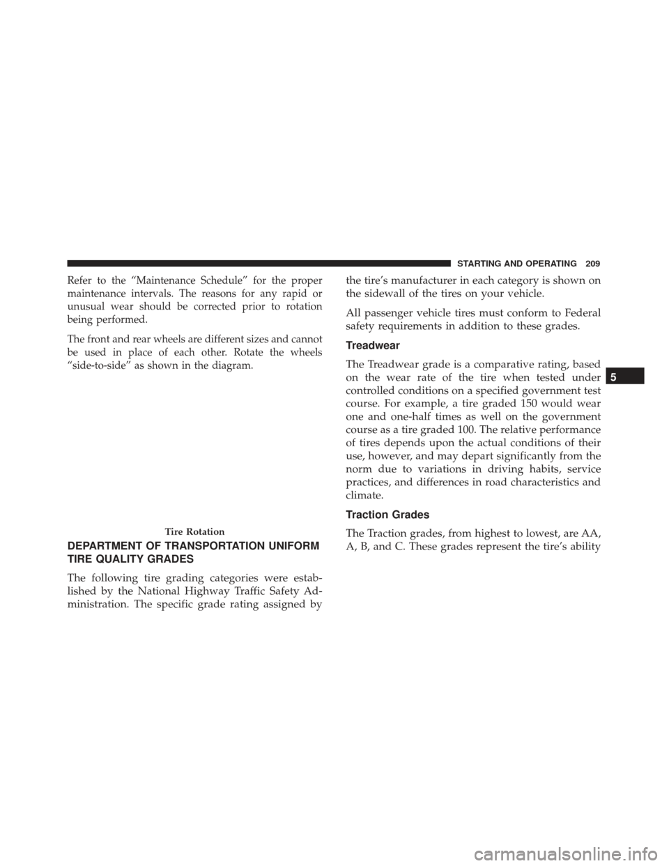
The front and rear wheels are different sizes and cannot
be used in place of each other. Rotate the wheels
“side-to-side” as shown in the diagram.
DEPARTMENT OF TRANSPORTATION UNIFORM
TIRE QUALITY GRADES
The following tire grading categories were estab-
lished by the National Highway Traffic Safety Ad-
ministration. The specific grade rating assigned bythe tire’s manufacturer in each category is shown on
the sidewall of the tires on your vehicle.
All passenger vehicle tires must conform to Federal
safety requirements in addition to these grades.
Treadwear
The Treadwear grade is a comparative rating, based
on the wear rate of the tire when tested under
controlled conditions on a specified government test
course. For example, a tire graded 150 would wear
one and one-half times as well on the government
course as a tire graded 100. The relative performance
of tires depends upon the actual conditions of their
use, however, and may depart significantly from the
norm due to variations in driving habits, service
practices, and differences in road characteristics and
climate.
Traction Grades
The Traction grades, from highest to lowest, are AA,
A, B, and C. These grades represent the tire’s ability
Tire Rotation
5
STARTING AND OPERATING 209
Page 212 of 300
to stop on wet pavement, as measured under con-
trolled conditions on specified government test sur-
faces of asphalt and concrete. A tire marked C may
have poor traction performance.
WARNING!
The traction grade assigned to this tire is based
on straight-ahead braking traction tests, and does
not include acceleration, cornering, hydroplan-
ing, or peak traction characteristics.
Temperature Grades
The temperature grades are A (the highest), B, and C,
representing the tire’s resistance to the generation of
heat and its ability to dissipate heat, when tested
under controlled conditions on a specified indoor
laboratory test wheel. Sustained high temperature
can cause the material of the tire to degenerate and
reduce tire life, and excessive temperature can lead
to sudden tire failure. The grade C corresponds to a
level of performance, which all passenger vehicle
tires must meet under the Federal Motor Vehicle
Safety Standard No. 109. Grades B and A represent higher levels of performance on the laboratory test
wheel, than the minimum required by law.
WARNING!
The temperature grade for this tire is established
for a tire that is properly inflated and not over-
loaded. Excessive speed, under-inflation, or ex-
cessive loading, either separately or in combina-
tion, can cause heat buildup and possible tire
failure.
TIRE PRESSURE MONITOR SYSTEM
The Tire Pressure Monitor System (TPMS) will warn the
driver of a low tire pressure based on the vehicle
recommended cold placard pressure.
The tire pressure will vary with temperature by about
1psi (7 kPa) for every 12°F (6.5°C). This means that
when the outside temperature decreases, the tire pres-
sure will decrease. Tire pressure should always be set
based on cold inflation tire pressure. This is defined as
the tire pressure after the vehicle has not been driven
for at least three hours, or driven less than 1 mile
(1.6 km) after a three hour period. The cold tire inflation
210 STARTING AND OPERATING
Page 213 of 300
pressure must not exceed the maximum inflation pres-
sure molded into the tire sidewall. Refer to “Tires –
General Information” in “Starting And Operating” for
information on how to properly inflate the vehicle’s
tires. The tire pressure will also increase as the vehicle is
driven. This is normal and there should be no adjust-
ment for this increased pressure.
The TPMS will warn the driver of a low tire pressure if
the tire pressure falls below the low-pressure warning
limit for any reason, including low temperature effects
and natural pressure loss through the tire.
The TPMS will continue to warn the driver of low tire
pressure as long as the condition exists, and will not
turn off until the tire pressure is at or above the
recommended cold placard pressure. Once the low tire
pressure warning (Tire Pressure Monitoring Telltale
Light) illuminates, you must increase the tire pressure
to the recommended cold placard pressure in order for
the “Tire Pressure Monitoring Telltale Light” to turn off.
The system will automatically update and the “Tire
Pressure Monitoring Telltale Light” will turn off once
the system receives the updated tire pressures. Thevehicle may need to be driven for up to 20 minutes
above 15 mph (24 km/h) in order for the TPMS to
receive this information.
For example, your vehicle may have a recommended
cold (parked for more than three hours) placard pres-
sure of 33 psi (227 kPa). If the ambient temperature is
68°F (20°C) and the measured tire pressure is 28 psi
(193 kPa), a temperature drop to 20°F (-7°C) will
decrease the tire pressure to approximately 24 psi
(165 kPa). This tire pressure is low enough to turn ON
the “Tire Pressure Monitoring Telltale Light.” Driving
the vehicle may cause the tire pressure to rise to
approximately 28 psi (193 kPa), but the “Tire Pressure
Monitoring Telltale Light” will still be on. In this
situation, the “Tire Pressure Monitoring Telltale Light”
will turn off only after the tires are inflated to the
vehicle’s recommended cold placard pressure value.
CAUTION!
•
The TPMS has been optimized for the original
equipment tires and wheels. TPMS pressures and
warnings have been established for the tire size
equipped on your vehicle. Undesirable system
(Continued)
5
STARTING AND OPERATING 211
Page 214 of 300
CAUTION!(Continued)
operation or sensor damage may result when
using replacement equipment that is not of the
same size, type, and/or style. The TPM sensor is
not designed for use on aftermarket wheels and
may contribute to a poor overall system perfor-
mance or sensor damage. Customers are encour-
aged to use OEM wheels to assure proper TPM
feature operation.
• Using aftermarket tire sealants may cause the Tire
Pressure Monitoring System (TPMS) sensor to
become inoperable. After using an aftermarket
tire sealant it is recommended that you take your
vehicle to an authorized dealership to have your
sensor function checked.
• After inspecting or adjusting the tire pressure,
always reinstall the valve stem cap. This will
prevent moisture and dirt from entering the valve
stem, which could damage the Tire Pressure
Monitoring Sensor. NOTE:
•
The TPMS is not intended to replace normal tire care
and maintenance, or to provide warning of a tire
failure or condition.
• The TPMS should not be used as a tire pressure
gauge while adjusting your tire pressure.
• Driving on a significantly under-inflated tire causes
the tire to overheat and can lead to tire failure.
• Under-inflation also reduces the high voltage battery
range and tire tread life, and may affect the vehicle’s
handling and stopping ability.
• It is particularly important for you to check the tire
pressure in all of the tires on your vehicle monthly
and to maintain the proper pressure.
• The TPMS is not a substitute for proper tire mainte-
nance, and it is the driver ’s responsibility to maintain
correct tire pressure using an accurate tire pressure
gauge, even if under-inflation has not reached the
level to trigger illumination of the “Tire Pressure
Monitoring Telltale Light”.
• Seasonal temperature changes will affect tire pres-
sure, and the TPMS will monitor the actual tire
pressure in the tire.
212 STARTING AND OPERATING
Page 215 of 300
TPM System
The Tire Pressure Monitor System (TPMS) uses wireless
technology with wheel rim mounted electronic sensors
to monitor tire pressure levels. Sensors, mounted to
each wheel as part of the valve stem, transmit tire
pressure readings to the receiver module.
The TPMS consists of the following components:
•Receiver module
• Four Tire Pressure Monitoring Sensors
• Various Tire Pressure Monitoring System messages,
which display in the instrument cluster
• Tire Pressure Monitoring Telltale Light
Tire Pressure Monitoring Low Pressure
Warnings
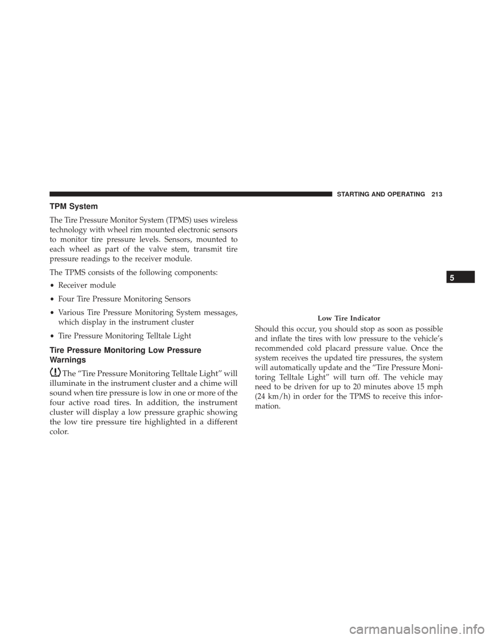
The “Tire Pressure Monitoring Telltale Light” will
illuminate in the instrument cluster and a chime will
sound when tire pressure is low in one or more of the
four active road tires. In addition, the instrument
cluster will display a low pressure graphic showing
the low tire pressure tire highlighted in a different
color.
Should this occur, you should stop as soon as possible
and inflate the tires with low pressure to the vehicle’s
recommended cold placard pressure value. Once the
system receives the updated tire pressures, the system
will automatically update and the “Tire Pressure Moni-
toring Telltale Light” will turn off. The vehicle may
need to be driven for up to 20 minutes above 15 mph
(24 km/h) in order for the TPMS to receive this infor-
mation.
Low Tire Indicator
5
STARTING AND OPERATING 213
Page 216 of 300
TPMS Warning
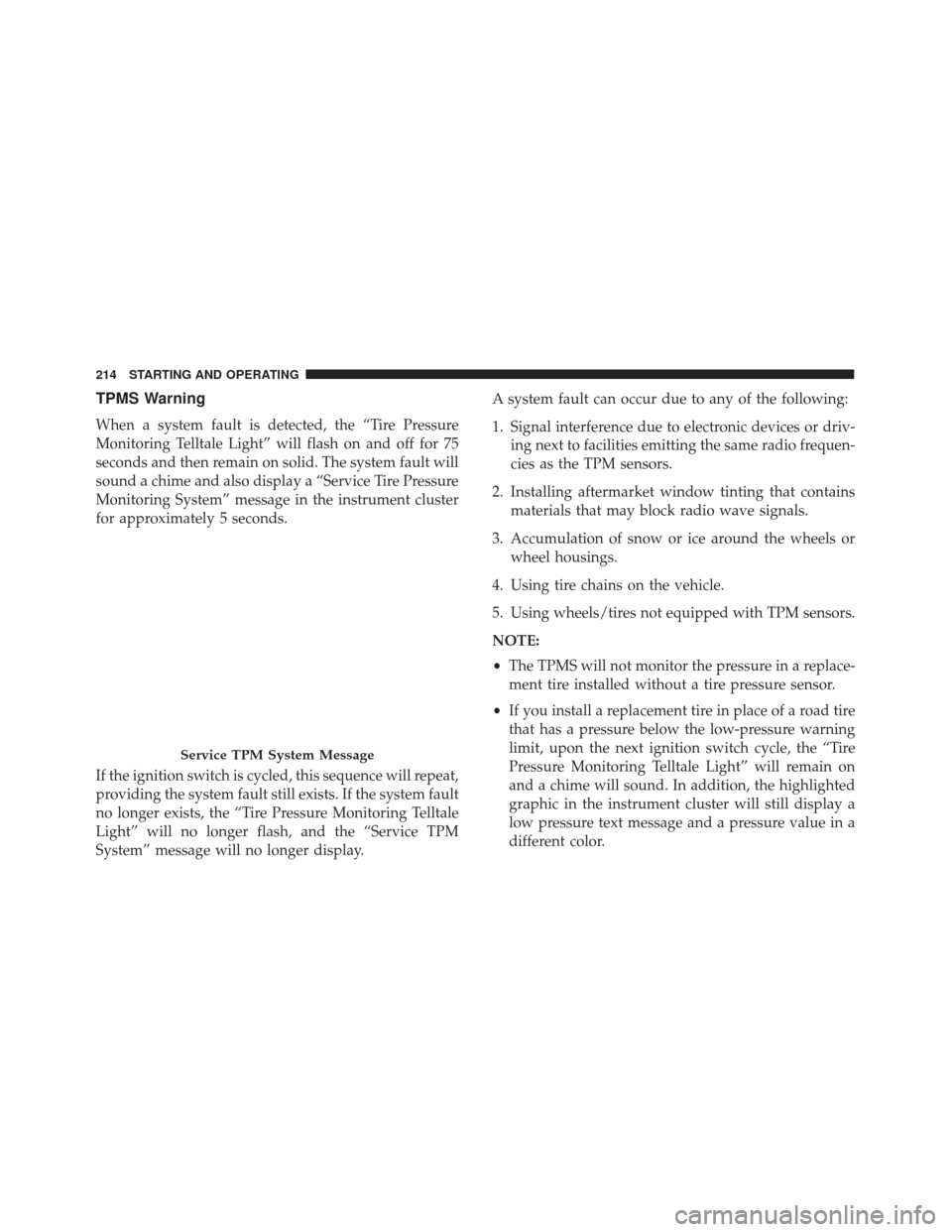
When a system fault is detected, the “Tire Pressure
Monitoring Telltale Light” will flash on and off for 75
seconds and then remain on solid. The system fault will
sound a chime and also display a “Service Tire Pressure
Monitoring System” message in the instrument cluster
for approximately 5 seconds.
If the ignition switch is cycled, this sequence will repeat,
providing the system fault still exists. If the system fault
no longer exists, the “Tire Pressure Monitoring Telltale
Light” will no longer flash, and the “Service TPM
System” message will no longer display.A system fault can occur due to any of the following:
1. Signal interference due to electronic devices or driv-
ing next to facilities emitting the same radio frequen-
cies as the TPM sensors.
2. Installing aftermarket window tinting that contains materials that may block radio wave signals.
3. Accumulation of snow or ice around the wheels or wheel housings.
4. Using tire chains on the vehicle.
5. Using wheels/tires not equipped with TPM sensors.
NOTE:
• The TPMS will not monitor the pressure in a replace-
ment tire installed without a tire pressure sensor.
• If you install a replacement tire in place of a road tire
that has a pressure below the low-pressure warning
limit, upon the next ignition switch cycle, the “Tire
Pressure Monitoring Telltale Light” will remain on
and a chime will sound. In addition, the highlighted
graphic in the instrument cluster will still display a
low pressure text message and a pressure value in a
different color.
Service TPM System Message
214 STARTING AND OPERATING
Page 217 of 300
•After driving the vehicle for up to 20 minutes above
15 mph (24 km/h), the “Tire Pressure Monitoring
Telltale Light” will flash on and off for 75 seconds
and then remain on solid. In addition, the instrument
cluster will display a “Service Tire Pressure Monitor-
ing System” message.
• For each subsequent ignition switch cycle, a chime
will sound, the “Tire Pressure Monitoring Telltale
Light” will flash on and off for 75 seconds and then
remain on solid, and the instrument cluster will
display a “Service TPM System” message.
Once you repair or replace the original road tire and
reinstall it, the TPMS will update automatically. In
addition, the “Tire Pressure Monitoring Telltale Light”
will turn off, as long as no tire pressure is below the
low-pressure warning limit in any of the four active
road tires. The vehicle may need to be driven for up to
20 minutes above 15 mph (24 km/h) in order for the
TPMS to receive this information.General Information
This device complies with Part 15 of the FCC rules and
RSS-210 of Industry Canada. Operation is subject to the
following two conditions:
(1) This device may not cause harmful interference.
(2) This device must accept any interference received,
including interference that may cause undesired opera-
tion.
NOTE: Changes or modifications not expressly ap-
proved by the party responsible for compliance could
void the user ’s authority to operate the equipment.
TRAILER TOWING
Trailer towing with this vehicle is not recommended.
5
STARTING AND OPERATING 215
Page 218 of 300
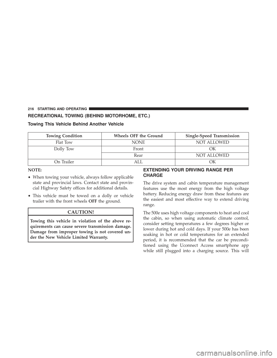
RECREATIONAL TOWING (BEHIND MOTORHOME, ETC.)
Towing This Vehicle Behind Another Vehicle
Towing ConditionWheels OFF the Ground Single-Speed Transmission
Flat Tow NONENOT ALLOWED
Dolly Tow FrontOK
Rear NOT ALLOWED
On Trailer ALLOK
NOTE:
• When towing your vehicle, always follow applicable
state and provincial laws. Contact state and provin-
cial Highway Safety offices for additional details.
• This vehicle must be towed on a dolly or vehicle
trailer with the front wheels OFFthe ground.
CAUTION!
Towing this vehicle in violation of the above re-
quirements can cause severe transmission damage.
Damage from improper towing is not covered un-
der the New Vehicle Limited Warranty.
EXTENDING YOUR DRIVING RANGE PER
CHARGE
The drive system and cabin temperature management
features use the most energy from the high voltage
battery. Reducing energy draw from these features are
the easiest and most effective way to extend driving
range.
The 500e uses high voltage components to heat and cool
the cabin, so when using automatic climate control,
consider setting temperatures a few degrees higher or
lower during hot and cold days. If your 500e has been
soaking in hot or cold temperatures for an extended
period, it is recommended that the car be precondi-
tioned using the Uconnect Access smartphone app
while still plugged into a charging source. This will
216 STARTING AND OPERATING
Page 219 of 300
allow 500e to use external power to establish a comfort-
able cabin temperature before the drive and allow the
battery to maintain the temperature at significantly
lower energy levels.
Additional tips:
•Keep tires properly inflated
• When practical, choose surface streets over the high-
way, and work to maintain a steady speed
• Avoid carrying nonessential cargo
• Be mindful of adding external accessories that may
increase aerodynamic drag
• Perform all scheduled maintenance at recommended
intervals
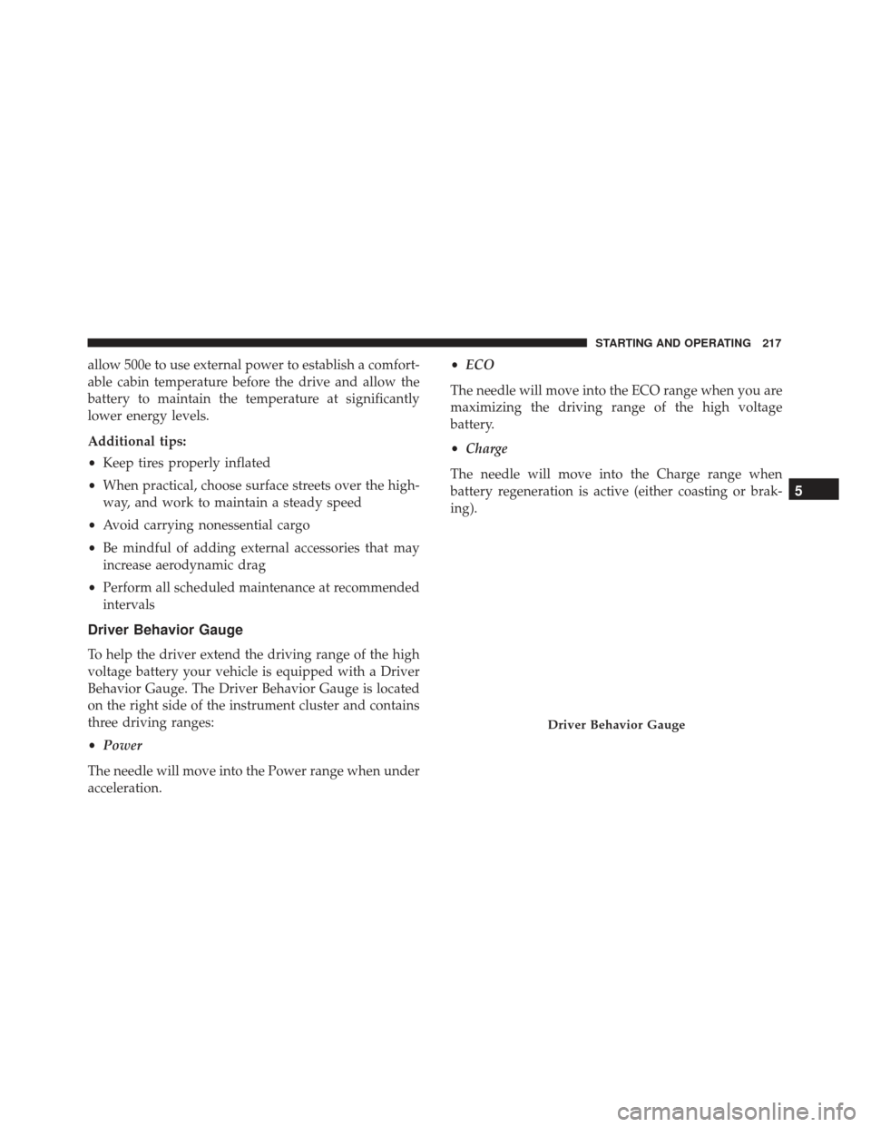
Driver Behavior Gauge
To help the driver extend the driving range of the high
voltage battery your vehicle is equipped with a Driver
Behavior Gauge. The Driver Behavior Gauge is located
on the right side of the instrument cluster and contains
three driving ranges:
• Power
The needle will move into the Power range when under
acceleration. •
ECO
The needle will move into the ECO range when you are
maximizing the driving range of the high voltage
battery.
• Charge
The needle will move into the Charge range when
battery regeneration is active (either coasting or brak-
ing).
Driver Behavior Gauge
5
STARTING AND OPERATING 217
Page 220 of 300
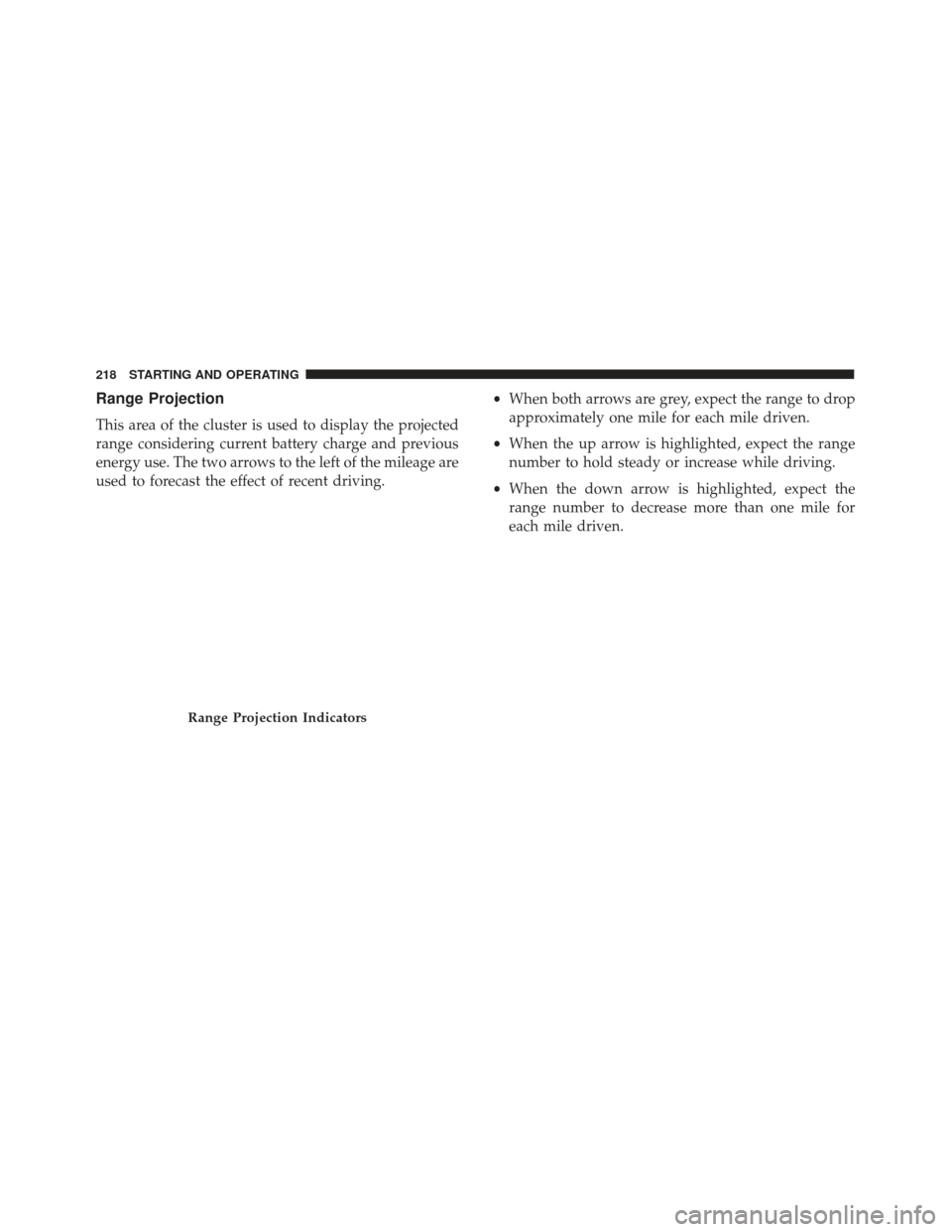
Range Projection
This area of the cluster is used to display the projected
range considering current battery charge and previous
energy use. The two arrows to the left of the mileage are
used to forecast the effect of recent driving.•
When both arrows are grey, expect the range to drop
approximately one mile for each mile driven.
• When the up arrow is highlighted, expect the range
number to hold steady or increase while driving.
• When the down arrow is highlighted, expect the
range number to decrease more than one mile for
each mile driven.
Range Projection Indicators
218 STARTING AND OPERATING