light FIAT 500L 2015 2.G Owner's Manual
[x] Cancel search | Manufacturer: FIAT, Model Year: 2015, Model line: 500L, Model: FIAT 500L 2015 2.GPages: 148, PDF Size: 3.77 MB
Page 97 of 148
Anti-Lock Brake System (ABS)/Electronic Stability Control (ESC) system.In this case, the
light will remain on until the condition has been corrected.If the problem is related to
the brake booster, the ABS pump will run when applying the brake, and a brake pedal
pulsation may be felt during each stop.
The dual brake system provides a reserve braking capacity in the event of a failure to a
portion of the hydraulic system.A leak in either half of the dual brake system is indicated
by the Brake Warning Light, which will turn on when the brake fluid level in the master
cylinder has dropped below a specified level.The light will remain on until the cause is
corrected.
Vehicles equipped with the Anti-Lock Brake System (ABS) are also equipped with Elec-
tronic Brake Force Distribution (EBD).In the event of an EBD failure, the Brake Warning
Light will turn on along with the ABS Light.Immediate repair to the ABS system is re-
quired.
Operation of the Brake Warning Light can be checked by turning the ignition switch from
the OFF position to the ON/RUN position.The light should illuminate for approximately
two seconds.The light should then turn off unless the parking brake is applied or a brake
fault is detected.If the light does not illuminate, have the light inspected by an authorized
dealer.
The light also will turn on when the parking brake is applied with the ignition switch in
the ON/RUN position.
NOTE:
This light shows only that the parking brake is applied.It does not show the degree of
brake application.
WARNING!
Driving a vehicle with the red brake light on is dangerous.Part of the brake system
may have failed.It will take longer to stop the vehicle.You could have a collision.Have
the vehicle checked immediately.
- Malfunction Indicator Light (MIL)
Certain conditions, such as a loose or missing gas cap, poor fuel quality, etc., may illumi-
nate the MIL after engine start.The vehicle should be serviced if the light stays on
through several typical driving cycles.In most situations, the vehicle will drive normally and
not require towing.
If the MIL flashes when the engine is running, serious conditions may exist that could lead
to immediate loss of power or severe catalytic converter damage.We recommend you
do not operate the vehicle.Have the vehicle serviced immediately.
WHAT TO DO IN EMERGENCIES
95
Page 98 of 148
- Electronic Stability Control (ESC) Activation / Malfunction
Indicator Light
The “ESC Activation/Malfunction Indicator Light” in the instrument cluster will come on
for four seconds when the ignition switch is turned to the ON/RUN position.If the “ESC
Activation/Malfunction Indicator Light” comes on continuously with the engine running, a
malfunction has been detected in the ESC system.If this light remains on, see your au-
thorized dealer as soon as possible to have the problem diagnosed and corrected.
NOTE:
•The “ESC Off Indicator Light” and the “ESC Activation/Malfunction Indicator Light”
come on momentarily each time the ignition switch is turned to ON/RUN.
•Each time the ignition is turned to ON/RUN, the ESC system will be ON even if it
was turned off previously.
•ESC Activation/Malfunction Light can blink during a ESC or TC intervention.
- Generic Warning Light
The Generic Warning Light will illuminate if any of the following conditions occur: Oil
Change Request, Engine Oil Pressure Sensor Failure, External Light Failure, Fuel Cut-Off
Not Available, Parking Sensor Failure, DST System Failure.
Electronic Throttle Control (ETC) Indicator Light
This light informs you of a problem with the system.
If a problem is detected, the light will come on while the engine is running.Cycle the
ignition when the vehicle has completely stopped and the shift lever is placed in the
PARK position; the light should turn off.
If the light remains lit with the engine running, your vehicle will usually be drivable.How-
ever, see an authorized dealer immediately.If the light is flashing when the engine is run-
ning, immediate service is required, and you may experience reduced performance, an
elevated/rough idle or engine stall, and your vehicle may require towing.
INSTRUMENT CLUSTER INDICATOR LIGHTS
Turn Signal Indicator
The arrows will flash with the exterior turn signals when the turn signal lever is oper-
ated.A tone will chime, and a EVIC message will appear if either turn signal is left on for
more than 1 mile (1.6 km).
NOTE:
If either indicator flashes at a rapid rate, check for a defective outside light bulb.
High Beam Indicator
Indicates that headlights are on high beam.
WHAT TO DO IN EMERGENCIES
96
Page 99 of 148
Vehicle Security Light
This light will flash rapidly for approximately 15 seconds when the vehicle security alarm
is arming.The light will flash at a slower speed continuously after the alarm is set.The
security light will also come on for about three seconds when the ignition is first turned
on.
Front Fog Light Indicator
This indicator will illuminate when the front fog lights are on.
- Electronic Speed Control SET Indicator
This indicator will illuminate when the cruising speed has been set.
- Electronic Stability Control (ESC) OFF Indicator Light
This light indicates the ESC system has been turned off by the driver.
Partial Off
This mode is entered by momentarily pressing the ESC Off switch.This mode is intended
for times when a more spirited driving experience is desired.It is also intended for driv-
ing in deep snow, sand or gravel conditions, when more wheel spin than ESC would nor-
mally allow is required to gain traction.To turn ESC on again, momentarily press the
switch again.This will restore the normal ESC On mode of operation.
Full Off
This mode is intended for off-highway or off-road use only and should not be used on
public roadways.In this mode, all TCS and ESC stability features are turned OFF, except
for the limited slip feature described in the TCS section.To enter the “Full Off ” mode,
depress and hold the ESC OFF switch for five seconds.After five seconds, the ESC OFF
Indicator Light will illuminate, and the “ESC OFF” message will display in the EVIC.To turn
ESC ON again, momentarily press the ESC OFF switch.
- Park/Headlight ON Indicator
This indicator will illuminate when the park lights or headlights are turned on.
- Power Steering System Warning
This light is used to manage the electrical warning of the EPS (Electric Power Steering
System).When the ignition is turned to the ON/RUN position, the warning light will illu-
minate momentarily.If the warning light stays on, cycle the ignition to the OFF position
and back to ON/RUN.If the warning light stays on, contact your authorized dealer.
If the warning light switches on while driving, you may not have steering assistance.Al-
though it will still be possible to steer the car, the effort needed to operate the steering
wheel could be increased: contact an authorized dealer as soon as possible.
- Defroster Indicator
Indicates that defroster is on.
WHAT TO DO IN EMERGENCIES
97
Page 106 of 148
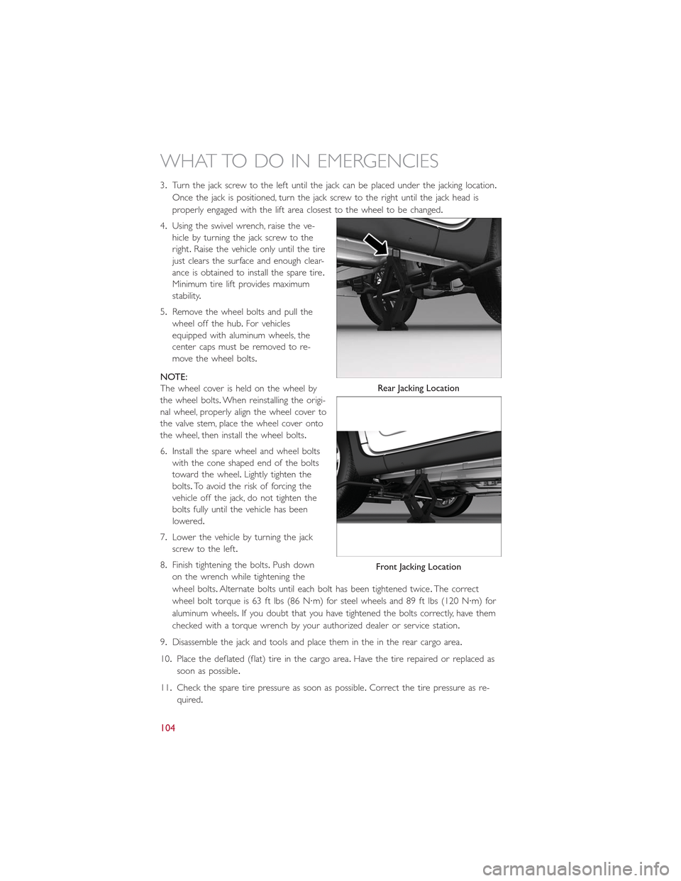
3.Turn the jack screw to the left until the jack can be placed under the jacking location.
Once the jack is positioned, turn the jack screw to the right until the jack head is
properly engaged with the lift area closest to the wheel to be changed.
4.Using the swivel wrench, raise the ve-
hicle by turning the jack screw to the
right.Raise the vehicle only until the tire
just clears the surface and enough clear-
ance is obtained to install the spare tire.
Minimum tire lift provides maximum
stability.
5.Remove the wheel bolts and pull the
wheel off the hub.For vehicles
equipped with aluminum wheels, the
center caps must be removed to re-
move the wheel bolts.
NOTE:
The wheel cover is held on the wheel by
the wheel bolts.When reinstalling the origi-
nal wheel, properly align the wheel cover to
the valve stem, place the wheel cover onto
the wheel, then install the wheel bolts.
6.Install the spare wheel and wheel bolts
with the cone shaped end of the bolts
toward the wheel.Lightly tighten the
bolts.To avoid the risk of forcing the
vehicle off the jack, do not tighten the
bolts fully until the vehicle has been
lowered.
7.Lower the vehicle by turning the jack
screw to the left.
8.Finish tightening the bolts.Push down
on the wrench while tightening the
wheel bolts.Alternate bolts until each bolt has been tightened twice.The correct
wheel bolt torque is 63 ft lbs (86 N·m) for steel wheels and 89 ft lbs (120 N·m) for
aluminum wheels.If you doubt that you have tightened the bolts correctly, have them
checked with a torque wrench by your authorized dealer or service station.
9.Disassemble the jack and tools and place them in the in the rear cargo area.
10.Place the deflated (flat) tire in the cargo area.Have the tire repaired or replaced as
soon as possible.
11.Check the spare tire pressure as soon as possible.Correct the tire pressure as re-
quired.
Rear Jacking Location
Front Jacking Location
WHAT TO DO IN EMERGENCIES
104
Page 128 of 148
MAINTENANCE PROCEDURES
For information on the maintenance procedures for your vehicle, please refer to “Mainte-
nance Procedures” in “Maintaining Your Vehicle” in your Owner’s Manual or applicable
supplement on the DVD for further details.
MAINTENANCE SCHEDULE
Your vehicle is equipped with an automatic oil change indicator system.The oil change
indicator system will remind you that it is time to take your vehicle in for scheduled
maintenance.
Based on engine operation conditions, the oil change indicator message will illuminate in
the instrument cluster.This means that service is required for your vehicle.Operating
conditions such as frequent short-trips, trailer tow and extremely hot or cold ambient
temperatures will influence when the “Change Oil” or “Oil Change Required” message is
displayed.Severe Operating Conditions can cause the change oil message to illuminate as
early as 3,500 miles (5,600 km) since last reset.Have your vehicle serviced as soon as
possible, within the next 500 miles (805 km).
Your authorized dealer will reset the oil change indicator message after completing the
scheduled oil change.If a scheduled oil change is performed by someone other than your
authorized dealer, the message can be reset by referring to the steps described under
“Electronic Vehicle Information Center (EVIC)” in “Understanding Your Instrument Panel”
in your Owners Manual on the DVD for further information.
NOTE:
Under no circumstances should oil change intervals exceed 10,000 miles (16,000 km) or
twelve months, whichever comes first.
Severe Duty All Models
Change Engine Oil at 4000 miles (6,500 km) if the vehicle is operated in a dusty and off
road environment.This type of vehicle use is considered Severe Duty
Once A Month Or Before A Long Trip:
•Check engine oil level.
•Check windshield washer fluid level.
•Check the tire inflation pressures and look for unusual wear or damage.
•Check the fluid levels of the coolant reservoir, and brake master cylinder reservoir, and
fill as needed.
•Check function of all interior and exterior lights.
MAINTAINING YOUR VEHICLE
126
Page 133 of 148
Cavity Maxi Fuse Mini Fuse Description
F21 – 15 Amp Blue Fuel Pump
F23 – 20 Amp Yellow Anti-Lock Brake Valves
F24 – 7.5 Amp Brown Stability Control System
F30 – 5 Amp Tan After Run Pump
F81 70 Amp Tan – PTC (Secondary)
F82 40 Amp Orange – Transmission
F83 40 Amp Orange – PTC (Primary)
F84 7.5 Amp Brown Transmission
F85 15 Amp Blue Front Power Outlet 12V
F86 – 15 Amp Blue Rear Power Outlet 12V
F88 7.5 Amp Brown Heated Mirrors
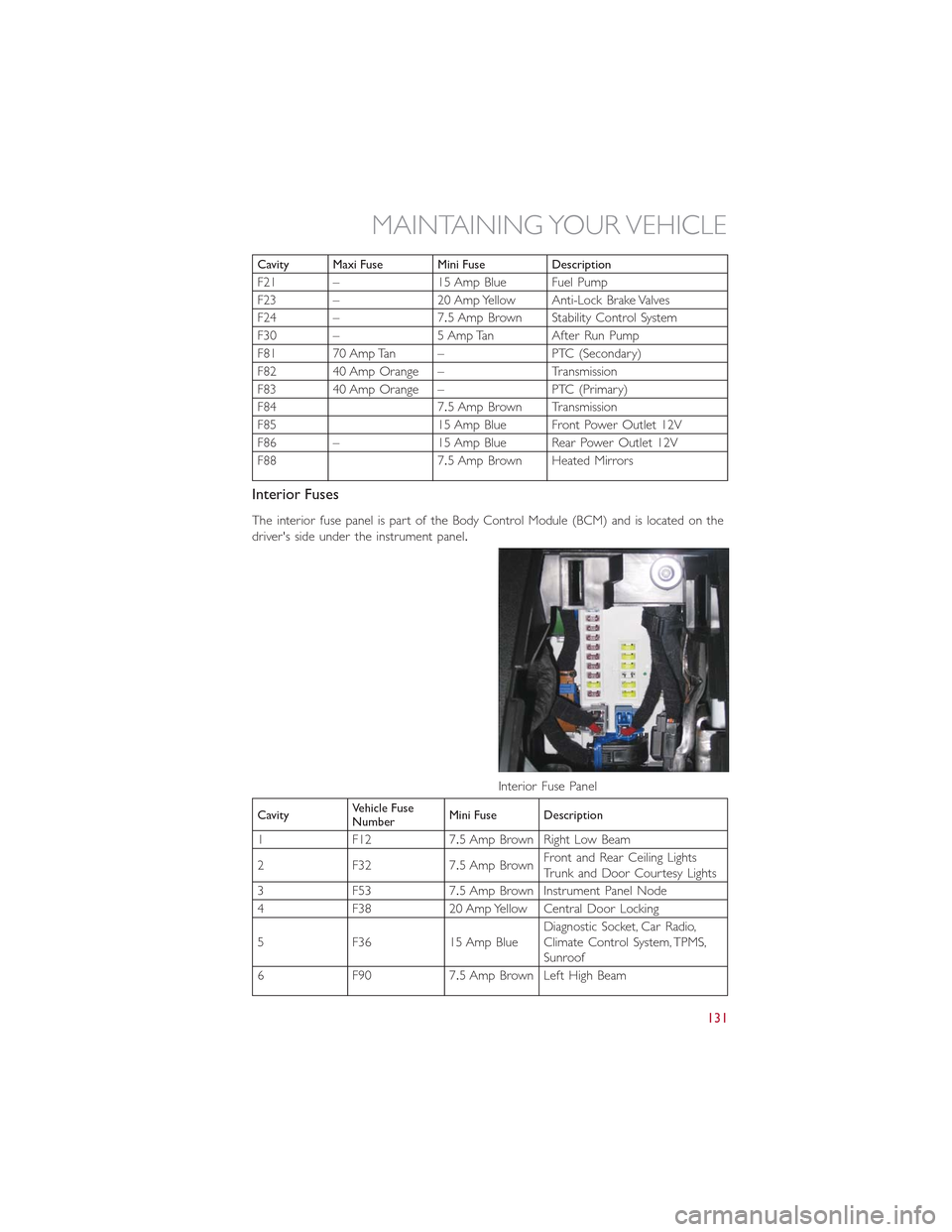
Interior Fuses
The interior fuse panel is part of the Body Control Module (BCM) and is located on the
driver's side under the instrument panel.
CavityVehicle FuseNumberMini Fuse Description
1 F12 7.5 Amp Brown Right Low Beam
2 F32 7.5 Amp BrownFront and Rear Ceiling LightsTr u n k a n d D o o r C o u r t e s y L i g h t s
3 F53 7.5 Amp Brown Instrument Panel Node
4 F38 20 Amp Yellow Central Door Locking
5 F36 15 Amp BlueDiagnostic Socket, Car Radio,Climate Control System, TPMS,Sunroof
6 F90 7.5 Amp Brown Left High Beam
Interior Fuse Panel
MAINTAINING YOUR VEHICLE
131
Page 134 of 148
CavityVehicle FuseNumberMini Fuse Description
7 F91 7.5 Amp Brown Right High Beam
8 F92 7.5 Amp Brown Left Fog Light
9 F93 7.5 Amp Brown Right Fog Light
10 F33 5 Amp Tan BSM, ESP
11 F34 20 Amp Yellow Rear Left Passenger Window
12 F49 20 Amp Yellow Rear Right Passenger Window
13 F43 20 Amp Yellow Bi-Directional Washer
14 F48 20 Amp Yellow Passenger Power Window
15 F13 7.5 Amp BrownLeft Low Beam, Headlamp Level-ing
16 F50 7.5 Amp Brown Airbag
17 F51 5 Amp Tan
Car Radio Switch, Climate Con-trol System, Stop Light, Clutch,Reverse Gear, Sunroof, ParkingSensor, Rear Camera
18 F37 7.5 Amp BrownStop Light Switch, InstrumentPanel Node
19 F49 5 Amp TanExterior Mirror, GPS, Electric Mir-ror, Parking Sensor
20 F31 5 Amp Tan Climate Control, Seat Regulation
21 F47 20 Amp Yellow Driver Power Window
Rear Interior Fuses
The rear interior fuse panel is located on the driver's side in the rear compartment.
CavityVehicle FuseNumberMini Fuse Description
1F6115AmpBlueLumbarRegulationSeats
2 F62 15 Amp Blue Heated Seats
3 F64 20 Amp Yellow Hi Fi System
4 F65 20 Amp Yellow Sun Blind
5 F66 20 Amp Yellow Sunroof
MAINTAINING YOUR VEHICLE
132
Page 141 of 148
AUTHENTIC ACCESSORIES BY MOPAR®
•The following highlights just some of the many Authentic FIAT Accessories by Mopar®
featuring a fit, finish, and functionality specifically for your FIAT 500L.
•In choosing Authentic Accessories you gain far more than expressive style, premium
protection, or extreme entertainment, you also benefit from enhancing your vehicle
with accessories that have been thoroughly tested and factory-approved.
•For the full line of Authentic FIAT Acces-
sories by Mopar®, visit your local dealer-
ship or online at mopar.com for U.S.
residents and mopar.ca for Canadian
residents.
NOTE:
All parts are subject to availability.
EXTERIOR:
•Chrome Hood Spear•17” Wheels•Front End Cover
•Chrome Mirror Cover•Wheel Locks•Molded Splash Guards
•Front Air Deflector•License Plate Frames•Vehicle Cover
•Roof And Body Graphics•Fender Badges•Valve Stem Caps
INTERIOR:
•Door Sill Guards•Pedal Kits•Premium Carpet Mats
•Cargo Tray•Key Covers•Slush Mats
•Headrest Coat Hanger•Roadside Safety Kit•Cargo Organizer
•Katzkin Leather Interiors
ELECTRONICS:
•GPS Tracking System(s)•Sound System Upgrades•Interior/Ambient Lighting
•Wi-Fi
CARRIERS:
•Bike Carrier•Luggage Carrier•Snowboard/Ski Carrier
•Hitch-mount Bike Carrier
PERFORMANCE:
•Cold Air Intake•Performance Exhaust
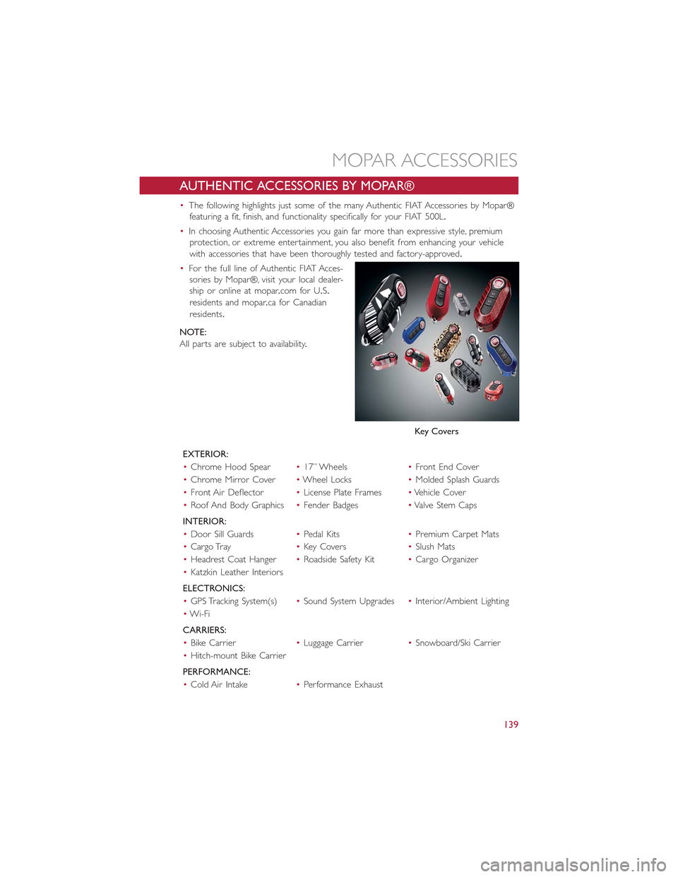
Key Covers
MOPAR ACCESSORIES
139
Page 142 of 148
FREQUENTLY ASKED QUESTIONS
GETTING STARTED
•How do I install my LATCH Equipped Child Seat? pg.16
•How do I adjust my rear seat? pg.23
ELECTRONICS
•What Sound System do I have? pg.40
•How do I set the clock on my radio? pg.43
•How do I set the presets on my radio? pg.45
•How do I use my USB/Audio Jack (AUX)? pg.47
•How do I pair my cell phone via Uconnect® Phone (Bluetooth® Hands Free Calling)?
pg.76
UTILITY
•How much can I tow with my FIAT 500L? pg.90
•How do I tow my FIAT 500L behind another vehicle? pg.140
WHAT TO DO IN EMERGENCIES
•What do I do if my TPMS warning light is blinking? pg.93
•How do I Jump-Start my vehicle? pg.113
•What should I do if my engine overheats? pg.98
•How do I change a flat tire? pg.99
MAINTAINING YOUR VEHICLE
•Where is my underhood fuse block located? pg.130
•Where is my interior fuse block located? pg.131
•What type of oil do I use? pg.124
•How often should I change my engines oil? pg.126
•What should my tire pressure be set at? pg.133
FREQUENTLY ASKED QUESTIONS
140
Page 143 of 148
Adding Engine Coolant (Antifreeze)....126
Adding Fuel.................37
Adding Washer Fluid............126
Air Bag
Advanced Front Air Bag.........12
Advance Front Air Bag.........12
Air Bags.................12
Air Bag Warning Light..........12
Driver Knee Air Bag...........13
Front Air Bag..............12Passenger Knee Air Bag.........13Rollover.................12Side Impacts...............12Air Bag Light.................92Air Bag, Side.................12Air Cleaner, Engine (Engine AirCleaner Filter).............126Air Conditioner Maintenance.......126Air Conditioning Refrigerant........126Air Conditioning System..........126AlarmDisarm The System............9Vehicle Security Alarm..........9Alarm (Security Alarm)..........9, 97Antifreeze (Engine Coolant).....124, 126Capacities...............124Disposal................126Anti-Lock Warning Light...........92Appearance Care.............126Audio Systems (Radio).........41, 45Automatic TransmissionFluid Type...............125
Battery...................126Body Mechanism Lubrication........126Brake Fluid.................125Brakes...................126Brake System................126Master Cylinder............126Warning Light..............94Break-In Recommendations, New Vehicle..26Bulb Replacement.............136Bulbs, Light.................136
Capacities, Antifreeze (Engine Coolant)..124Capacities, Fluid...............124Caps, FillerFuel..................120
Oil (Engine)..............126
Car Washes................126
Changing A Flat Tire.............99
Charging System Light............92
Child Restraint................15
Child Restraints
Center Seat LATCH...........16
Installing Child Restraints Using The
Vehicle Seat Belt.............17
Lower Anchors And Tethers ForChildren.................17Using The Top Tether Anchorage....17CleaningWheels................126Windshield Wiper Blades.......126Climate ControlAutomatic................32Manual..................31Clock....................43Clock Setting................43Cluster Warning/Indicator LightsAnti-Lock Brake (ABS) Light......92Brake Warning Light...........94Charging System Light.........92Electronic Speed Control SETIndicator.................97Electronic Throttle Control (ETC)Indicator Light..............96Engine Temperature Warning Light...94Front Fog Light Indicator........97High Beam Indicator..........96Malfunction Indicator Light (MIL)....95Oil Pressure Warning Light.......92Park/Headlight ON Indicator......97Tire Pressure Monitoring System(TPMS) Light..............93Turn Signal Indicator..........96Vehicle Security Light..........97Clutch...................126Clutch Fluid................126Compact Spare Tire............134Coolant (Antifreeze)............124Cooling System...............126Adding Coolant (Antifreeze).....126Coolant Level.............126Disposal Of Used Coolant......126Drain, Flush, And Refill.........126Inspection...............126
INDEX
141