lock FIAT 500L LIVING 2015 2.G Owner's Manual
[x] Cancel search | Manufacturer: FIAT, Model Year: 2015, Model line: 500L LIVING, Model: FIAT 500L LIVING 2015 2.GPages: 224, PDF Size: 5.92 MB
Page 74 of 224
SEAT BELTS
69) 70)
USING THE SEAT BELTSThe driver is responsible for respecting,
and ensuring that all the other
occupants of the vehicle also respect,
the local laws in force in relation to
the use of the seat belts.
Always fasten the seat belts before
setting off.
The seat belt should be worn keeping
the torso straight and rested against
the backrest.
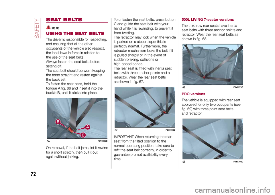
To fasten the seat belts, hold the
tongue A fig. 66 and insert it into the
buckle B, until it clicks into place.
On removal, if the belt jams, let it rewind
for a short stretch, then pull it out
again without jerking.To unfasten the seat belts, press button
C and guide the seat belt with your
hand while it is rewinding, to prevent it
from twisting.
The retractor may lock when the vehicle
is parked on a steep slope: this is
perfectly normal. Furthermore, the
retractor mechanism locks the belt if it
is pulled sharply or in the event of
sudden braking, collisions or
high-speed bends.
The rear seat is fitted with inertia seat
belts with three anchor points and a
retractor. Wear the rear seat belts
as shown in fig. 67.
IMPORTANT When returning the rear
seat from the tilted position to the
normal operating position, take care to
refit the seat belt correctly, in order to
guarantee prompt availability every
time.
500L LIVING 7-seater versionsThe third row rear seats have inertia
seat belts with three anchor points and
retractor. Wear the rear seat belts as
shown in fig. 68.PRO versionsThe vehicle is equipped with rear seat
approved for only two occupants (see
fig. 69) with three point seat belts
and retractor.
66
F0Y0085C
67
F0Y0086C
68
F0Y0379C
69
F0Y0792C
72
SAFETY
9-1-2015 12:9 Pagina 72
Page 108 of 224
Emergency refuellingProceed as follows:
❒open the luggage compartment and
take the adapter, located in the tool box
or in the Fix&Go Automatic container
(according to the versions);
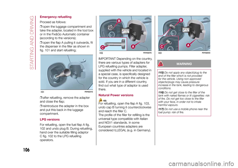
❒open the flap A pulling it outwards, fit
the dispenser in the filler as shown in
fig. 101 and start refuelling;
❒after refuelling, remove the adapter
and close the flap;
❒reintroduce the adapter in the box
and put this back in the luggage
compartment.LPG versionsFor refuelling, open the fuel flap A fig.
102 and undo plug B. During refuelling,
hand over the suitable filling adaptor
C fig. 102 to the LPG refuelling
operators.IMPORTANT Depending on the country,
there are various types of adapters for
LPG refuelling pumps. Filler adapter,
supplied with the vehicle and located in
a special case, is specifically designed
for the country in which the vehicle is
sold. If you are in a different country,
find out what type of adaptor is used
there.
Natural Power versions
62)
For refuelling, open the flap A fig. 103,
undo cap B turning it counterclockwise
and reach the filler C.
The profile of the filler for refilling is the
universal type compatible with Italian
and NGV1 standards. In some
European countries adapters are
considered ILLEGAL (e.g. in Germany).
WARNING
115)Do not apply any object/plug to the
end of the filler which is not provided
for the vehicle. Using non-approved
objects/plugs may cause pressure
increase in the tank, leading to dangerous
conditions.
116)Do not get close to the filler of the
tank with naked flames or lit cigarettes: risk
of fire. Do not get too close to the filler
with your face, in order not to inhale
harmful vapours.
117)Do not use a mobile phone near the
fuel pump: risk of fire.
101
F0Y0231C
102
F0Y0327C
103
F0Y0254C
106
STARTING AND DRIVING
9-1-2015 12:9 Pagina 106
Page 111 of 224
HAZARD WARNING
LIGHTSCONTROLPress button fig. 104 to switch the
lights on/off. When the hazard warning
lights are on, the
and
warning
lights flash.
Emergency brakingIn the event of emergency braking the
hazard warning lights switch on
automatically as well as warning lights
and
in the instrument panel.
The lights switch off automatically when
emergency braking ceases.
CHANGING A WHEEL
118) 119) 120) 121) 122)
63)
JACKPlease note that:
❒the jack weight is 1,76 kg;
❒the jack requires no adjustment;
❒the jack cannot be repaired and in
the event of a fault it must be replaced
by another original one;
❒no tool other than its cranking device
may be fitted on the jack.WHEEL REPLACEMENT
PROCEDUREProceed as follows:
❒stop the vehicle in a position that is
not dangerous for oncoming traffic
where you can change the wheel safely.
The ground should be flat if possible,
and sufficiently firm;
❒switch off the engine, pull up the
handbrake and engage the 1
stgear or
reverse. Wear the reflective safety
jacket (compulsory by law) before
getting out of the vehicle;
❒500L versions: open the tailgate and
lift the carpet;❒500L LIVING versions: open the
tailgate, lift the load platform of
the "Cargo Magic Space" holding it with
one hand and then take the toolbox.
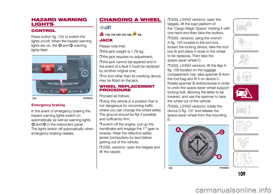
❒500L versions: using the wrench
A fig. 105 located in the tool box,
loosen the locking device, take the tool
box B and place it close to the wheel
to be replaced. Then take the
space-saver wheel C;
❒500L LIVING versions: lift the flap A
fig. 106 located on the luggage
compartment mat, take spanner B from
the tool bag and fit it on device C.
Rotate spanner B anticlockwise in order
to undo the space-saver wheel support
locking bolt, allowing the latter to be
lowered, and use the spanner to take
the wheel out of the vehicle;
❒500L LIVING versions: rotate the
device D fig. 107 and release the
space-saver wheel from the mounting
E;
104
F0Y0037C
105
F0Y0096C
109
9-1-2015 12:9 Pagina 109
Page 112 of 224
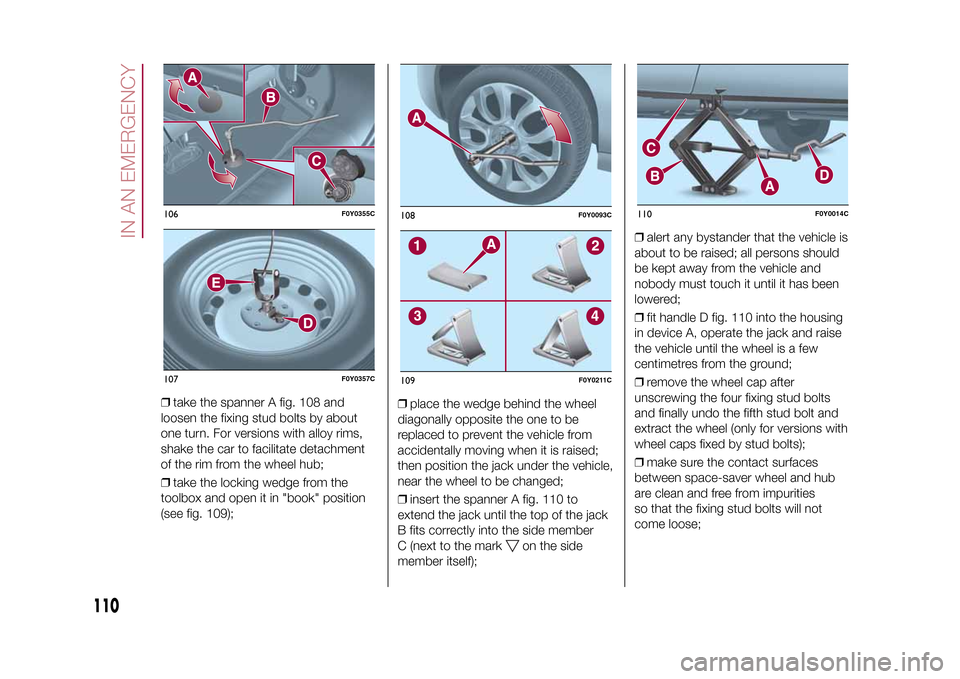
❒take the spanner A fig. 108 and
loosen the fixing stud bolts by about
one turn. For versions with alloy rims,
shake the car to facilitate detachment
of the rim from the wheel hub;
❒take the locking wedge from the
toolbox and open it in "book" position
(see fig. 109);❒place the wedge behind the wheel
diagonally opposite the one to be
replaced to prevent the vehicle from
accidentally moving when it is raised;
then position the jack under the vehicle,
near the wheel to be changed;
❒insert the spanner A fig. 110 to
extend the jack until the top of the jack
B fits correctly into the side member
C (next to the mark
on the side
member itself);❒alert any bystander that the vehicle is
about to be raised; all persons should
be kept away from the vehicle and
nobody must touch it until it has been
lowered;
❒fit handle D fig. 110 into the housing
in device A, operate the jack and raise
the vehicle until the wheel is a few
centimetres from the ground;
❒remove the wheel cap after
unscrewing the four fixing stud bolts
and finally undo the fifth stud bolt and
extract the wheel (only for versions with
wheel caps fixed by stud bolts);
❒make sure the contact surfaces
between space-saver wheel and hub
are clean and free from impurities
so that the fixing stud bolts will not
come loose;
106
F0Y0355C
107
F0Y0357C
108
F0Y0093C
109
F0Y0211C
110
F0Y0014C
110
IN AN EMERGENCY
9-1-2015 12:9 Pagina 110
Page 113 of 224
❒fit the space-saver wheel by inserting
the first stud bolt for two threads into
the hole closest to the valve; then,
tighten the stud bolt by some threads
and proceed in the same way for the
others;
❒take the spanner A fig. 105 and fully
tighten the fixing stud bolts;
❒operate the jack handle D to lower
the car. Then extract the jack;
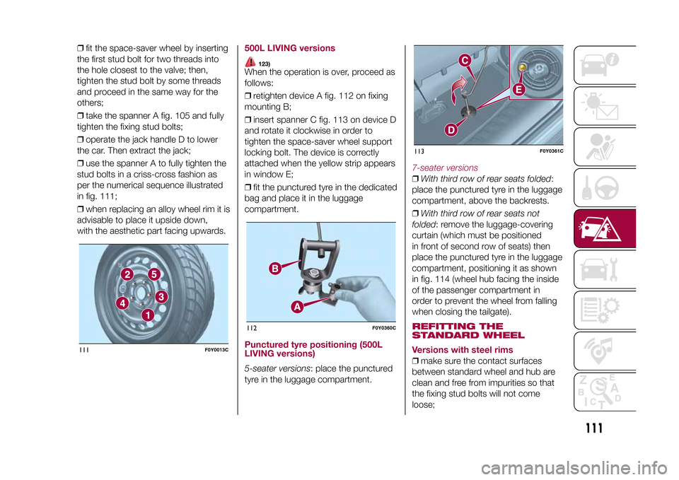
❒use the spanner A to fully tighten the
stud bolts in a criss-cross fashion as
per the numerical sequence illustrated
in fig. 111;
❒when replacing an alloy wheel rim it is
advisable to place it upside down,
with the aesthetic part facing upwards.
500L LIVING versions
123)
When the operation is over, proceed as
follows:
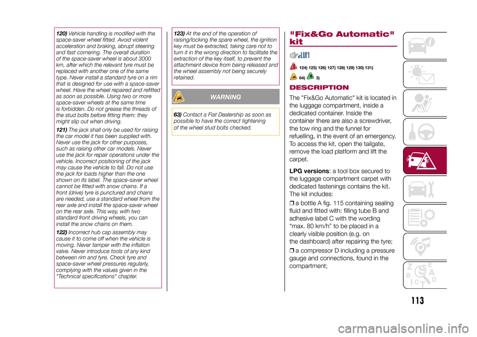
❒retighten device A fig. 112 on fixing
mounting B;
❒insert spanner C fig. 113 on device D
and rotate it clockwise in order to
tighten the space-saver wheel support
locking bolt. The device is correctly
attached when the yellow strip appears
in window E;
❒fit the punctured tyre in the dedicated
bag and place it in the luggage
compartment.Punctured tyre positioning (500L
LIVING versions)5-seater versions: place the punctured
tyre in the luggage compartment.
7-seater versions❒With third row of rear seats folded:
place the punctured tyre in the luggage
compartment, above the backrests.
❒With third row of rear seats not
folded: remove the luggage-covering
curtain (which must be positioned
in front of second row of seats) then
place the punctured tyre in the luggage
compartment, positioning it as shown
in fig. 114 (wheel hub facing the inside
of the passenger compartment in
order to prevent the wheel from falling
when closing the tailgate).REFITTING THE
STANDARD WHEEL
Versions with steel rims❒make sure the contact surfaces
between standard wheel and hub are
clean and free from impurities so that
the fixing stud bolts will not come
loose;
111
F0Y0013C
112
F0Y0360C
113
F0Y0361C
111
9-1-2015 12:9 Pagina 111
Page 115 of 224
120)Vehicle handling is modified with the
space-saver wheel fitted. Avoid violent
acceleration and braking, abrupt steering
and fast cornering. The overall duration
of the space-saver wheel is about 3000
km, after which the relevant tyre must be
replaced with another one of the same
type. Never install a standard tyre on a rim
that is designed for use with a space-saver
wheel. Have the wheel repaired and refitted
as soon as possible. Using two or more
space-saver wheels at the same time
is forbidden. Do not grease the threads of
the stud bolts before fitting them: they
might slip out when driving.
121)The jack shall only be used for raising
the car model it has been supplied with.
Never use the jack for other purposes,
such as raising other car models. Never
use the jack for repair operations under the
vehicle. Incorrect positioning of the jack
may cause the vehicle to fall. Do not use
the jack for loads higher than the one
shown on its label. The space-saver wheel
cannot be fitted with snow chains. If a
front (drive) tyre is punctured and chains
are needed, use a standard wheel from the
rear axle and install the space-saver wheel
on the rear axle. This way, with two
standard front driving wheels, you can
install the snow chains on them.
122)Incorrect hub cap assembly may
cause it to come off when the vehicle is
moving. Never tamper with the inflation
valve. Never introduce tools of any kind
between rim and tyre. Check tyre and
space-saver wheel pressures regularly,
complying with the values given in the
"Technical specifications" chapter.123)At the end of the operation of
raising/locking the spare wheel, the ignition
key must be extracted, taking care not to
turn it in the wrong direction to facilitate the
extraction of the key itself, to prevent the
attachment device from being released and
the wheel assembly not being securely
retained.
WARNING
63)Contact a Fiat Dealership as soon as
possible to have the correct tightening
of the wheel stud bolts checked.
"Fix&Go Automatic"
kit
124) 125) 126) 127) 128) 129) 130) 131)64)
3)
DESCRIPTIONThe "Fix&Go Automatic" kit is located in
the luggage compartment, inside a
dedicated container. Inside the
container there are also a screwdriver,
the tow ring and the funnel for
refuelling, in the event of an emergency.
To access the kit, open the tailgate,
remove the load platform and lift the
carpet.
LPG versions: a tool box secured to
the luggage compartment carpet with
dedicated fastenings contains the kit.
The kit includes:
❒a bottle A fig. 115 containing sealing
fluid and fitted with: filling tube B and
adhesive label C with the wording
“max. 80 km/h” to be placed in a
clearly visible position (e.g. on
the dashboard) after repairing the tyre;
❒a compressor D including a pressure
gauge and connections, found in the
compartment;
113
9-1-2015 12:9 Pagina 113
Page 120 of 224
FRONT UPPER LIGHT
CLUSTERThis contains the bulbs for direction
indicators and dipped beam headlights.
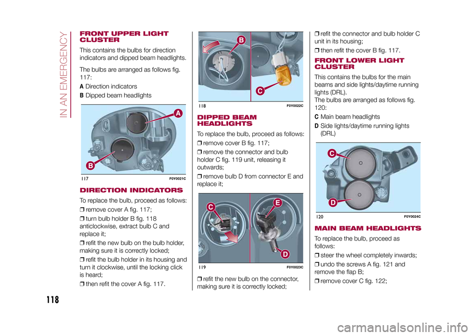
The bulbs are arranged as follows fig.
117:A
Direction indicators
B
Dipped beam headlights
DIRECTION INDICATORSTo replace the bulb, proceed as follows:
❒remove cover A fig. 117;
❒turn bulb holder B fig. 118
anticlockwise, extract bulb C and
replace it;
❒refit the new bulb on the bulb holder,
making sure it is correctly locked;
❒refit the bulb holder in its housing and
turn it clockwise, until the locking click
is heard;
❒then refit the cover A fig. 117.
DIPPED BEAM
HEADLIGHTSTo replace the bulb, proceed as follows:
❒remove cover B fig. 117;
❒remove the connector and bulb
holder C fig. 119 unit, releasing it
outwards;
❒remove bulb D from connector E and
replace it;
❒refit the new bulb on the connector,
making sure it is correctly locked;❒refit the connector and bulb holder C
unit in its housing;
❒then refit the cover B fig. 117.
FRONT LOWER LIGHT
CLUSTERThis contains the bulbs for the main
beams and side lights/daytime running
lights (DRL).
The bulbs are arranged as follows fig.
120:C
Main beam headlights
D
Side lights/daytime running lights
(DRL)
MAIN BEAM HEADLIGHTSTo replace the bulb, proceed as
follows:
❒steer the wheel completely inwards;
❒undo the screws A fig. 121 and
remove the flap B;
❒remove cover C fig. 122;
117
F0Y0021C
118
F0Y0022C
119
F0Y0023C
120
F0Y0024C
118
IN AN EMERGENCY
9-1-2015 12:9 Pagina 118
Page 121 of 224
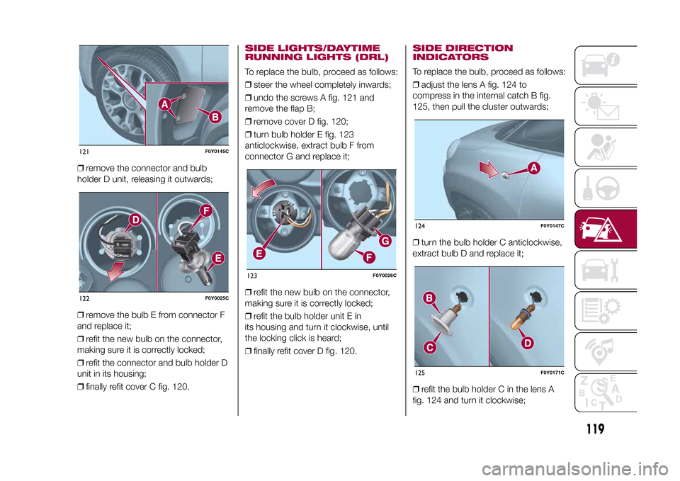
❒remove the connector and bulb
holder D unit, releasing it outwards;
❒remove the bulb E from connector F
and replace it;
❒refit the new bulb on the connector,
making sure it is correctly locked;
❒refit the connector and bulb holder D
unit in its housing;
❒finally refit cover C fig. 120.
SIDE LIGHTS/DAYTIME
RUNNING LIGHTS (DRL)To replace the bulb, proceed as follows:
❒steer the wheel completely inwards;
❒undo the screws A fig. 121 and
remove the flap B;
❒remove cover D fig. 120;
❒turn bulb holder E fig. 123
anticlockwise, extract bulb F from
connector G and replace it;
❒refit the new bulb on the connector,
making sure it is correctly locked;
❒refit the bulb holder unit E in
its housing and turn it clockwise, until
the locking click is heard;
❒finally refit cover D fig. 120.
SIDE DIRECTION
INDICATORSTo replace the bulb, proceed as follows:
❒adjust the lens A fig. 124 to
compress in the internal catch B fig.
125, then pull the cluster outwards;
❒turn the bulb holder C anticlockwise,
extract bulb D and replace it;
❒refit the bulb holder C in the lens A
fig. 124 and turn it clockwise;
121
F0Y0145C
122
F0Y0025C
123
F0Y0026C
124
F0Y0147C
125
F0Y0171C
119
9-1-2015 12:9 Pagina 119
Page 123 of 224
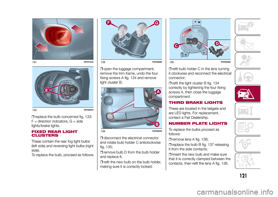
❒replace the bulb concerned fig. 133:
F = direction indicators, G = side
lights/brake lights.FIXED REAR LIGHT
CLUSTERSThese contain the rear fog light bulbs
(left side) and reversing light bulbs (right
side).
To replace the bulb, proceed as follows:❒open the luggage compartment,
remove the trim frame, undo the four
fixing screws A fig. 134 and remove
light cluster B;
❒disconnect the electrical connector
and rotate bulb holder C anticlockwise
fig. 135;
❒remove bulb D from the bulb holder
and replace it;
❒refit the new bulb on the bulb holder,
making sure it is correctly locked;❒refit bulb holder C in the lens turning
it clockwise and reconnect the electrical
connector;
❒refit the light cluster B fig. 134
correctly by tightening the four fixing
screws A, then close the luggage
compartment.
THIRD BRAKE LIGHTSThese are located in the tailgate and
are LED lights. For replacement,
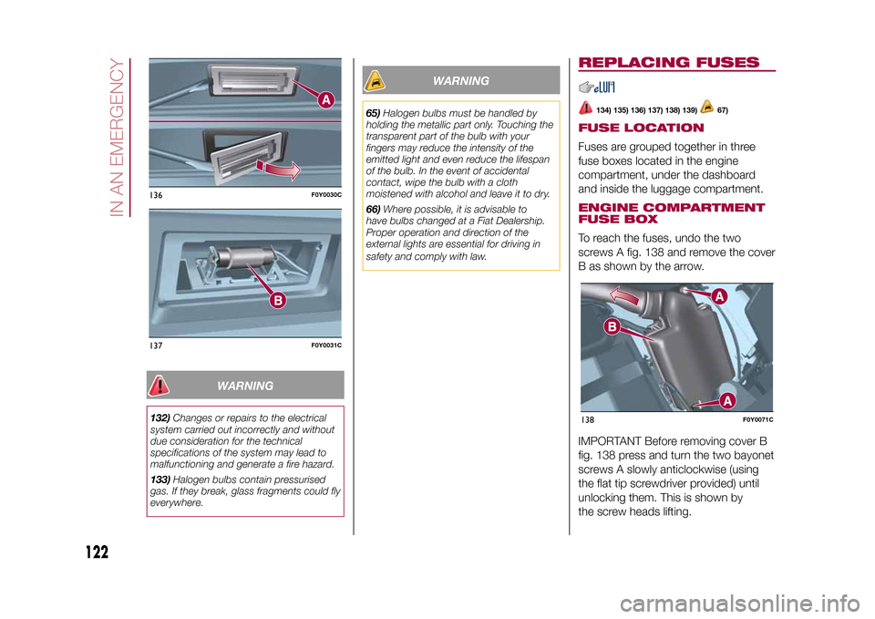
contact a Fiat Dealership.NUMBER PLATE LIGHTSTo replace the bulbs proceed as
follows:
❒remove lens A fig. 136;
❒replace the bulb B fig. 137 releasing
it from the side contacts;
❒Insert the new bulb and make sure
that it is correctly clamped between the
contacts, then refit the lens A fig. 136.
131
F0Y0151C
132
F0Y0027C
133
F0Y0028C
134
F0Y0032C
135
F0Y0029C
121
9-1-2015 12:9 Pagina 121
Page 124 of 224
WARNING
132)Changes or repairs to the electrical
system carried out incorrectly and without
due consideration for the technical
specifications of the system may lead to
malfunctioning and generate a fire hazard.
133)Halogen bulbs contain pressurised
gas. If they break, glass fragments could fly
everywhere.
WARNING
65)Halogen bulbs must be handled by
holding the metallic part only. Touching the
transparent part of the bulb with your
fingers may reduce the intensity of the
emitted light and even reduce the lifespan
of the bulb. In the event of accidental
contact, wipe the bulb with a cloth
moistened with alcohol and leave it to dry.
66)Where possible, it is advisable to
have bulbs changed at a Fiat Dealership.
Proper operation and direction of the
external lights are essential for driving in
safety and comply with law.
REPLACING FUSES
134) 135) 136) 137) 138) 139)
67)
FUSE LOCATIONFuses are grouped together in three
fuse boxes located in the engine
compartment, under the dashboard
and inside the luggage compartment.ENGINE COMPARTMENT
FUSE BOXTo reach the fuses, undo the two
screws A fig. 138 and remove the cover
B as shown by the arrow.
IMPORTANT Before removing cover B
fig. 138 press and turn the two bayonet
screws A slowly anticlockwise (using
the flat tip screwdriver provided) until
unlocking them. This is shown by
the screw heads lifting.
136
F0Y0030C
137
F0Y0031C
138
F0Y0071C
122
IN AN EMERGENCY
9-1-2015 12:9 Pagina 122