clock FIAT 500L LIVING 2015 2.G Owners Manual
[x] Cancel search | Manufacturer: FIAT, Model Year: 2015, Model line: 500L LIVING, Model: FIAT 500L LIVING 2015 2.GPages: 224, PDF Size: 5.92 MB
Page 26 of 224
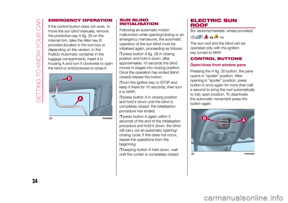
EMERGENCY OPERATIONIf the control button does not work, to
move the sun blind manually, remove
the protective cap A fig. 29 on the
internal trim, take the Allen key B
provided (located in the tool box or,
depending on the version, in the
Fix&Go Automatic container in the
luggage compartment), insert it in
housing A and turn it clockwise to open
the blind or anticlockwise to close it.
SUN BLIND
INITIALISATIONFollowing an automatic motion
malfunction while opening/closing or an
emergency manoeuvre, the automatic
operation of the sun blind must be
initialised again, proceeding as follows:
❒press button A fig. 28 in closing
position and hold it down: after
approximately 10 seconds the blind
moves in stages into closing position.
Once the operation has ended (blind
closed) release the button;
❒turn the ignition key to STOP and
keep it there for 10 seconds; then turn
it to MAR;
❒press button A in closing position
and hold it down until the blind is
completely closed: the initialisation
procedure has ended;
❒press button A again within 3
seconds of the end of the initialisation
procedure and hold it down: the blind
will carry out an automatic opening/
closing cycle: if this does not occur,
repeat the operations from the
beginning;
❒keeping button A held down, wait
until the curtain is completely closed.
ELECTRIC SUN
ROOF(for versions/markets, where provided)
23)
11)
The sun roof and the blind can be
operated only with the ignition
key turned to MAR.CONTROL BUTTONS
Open/close front window panePressing the A fig. 30 button, the pane
opens in "spoiler" position. After
opening in “spoiler” position, press
button A once again for more than half
a second to bring the roof automatically
to fully open position. To deactivate
the automatic movement press the
button again.
29
F0Y0285C
30
F0Y0120C
24
GETTING TO KNOW YOUR CAR
9-1-2015 12:9 Pagina 24
Page 27 of 224
From the fully open position press
button A: the front glass pane will move
into the "spoiler" position. In this
condition, pressing the button again for
more than half a second, the roof will
automatically move the fully closed
position. To deactivate the automatic
movement press the button again.Sun blind movementPressing the B fig. 30 button: the blind
will move towards the rear part of the
vehicle, until it is fully open. With blind
fully open press button B: the blind
will move towards the front part of the
vehicle, until it is fully closed. During the
blind automatic opening and closing
stages, press the button again to
interrupt the blind movement.EMERGENCY OPERATIONIn the case of control buttons operation
failure, the sun blind and the sun roof
can be moved manually, proceeding as
described below:
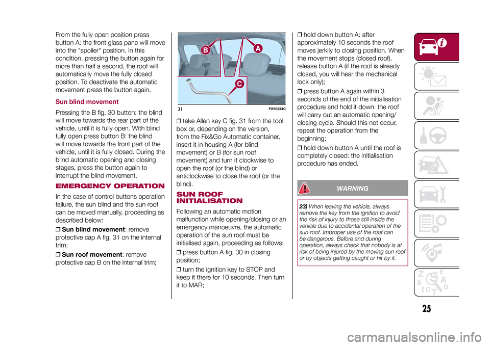
❒Sun blind movement: remove
protective cap A fig. 31 on the internal
trim;
❒Sun roof movement: remove
protective cap B on the internal trim;❒take Allen key C fig. 31 from the tool
box or, depending on the version,
from the Fix&Go Automatic container,
insert it in housing A (for blind
movement) or B (for sun roof
movement) and turn it clockwise to
open the roof (or the blind) or
anticlockwise to close the roof (or the
blind).
SUN ROOF
INITIALISATIONFollowing an automatic motion
malfunction while opening/closing or an
emergency manoeuvre, the automatic
operation of the sun roof must be
initialised again, proceeding as follows:
❒press button A fig. 30 in closing
position;
❒turn the ignition key to STOP and
keep it there for 10 seconds. Then turn
it to MAR;❒hold down button A: after
approximately 10 seconds the roof
moves jerkily to closing position. When
the movement stops (closed roof),
release button A (if the roof is already
closed, you will hear the mechanical
lock only);
❒press button A again within 3
seconds of the end of the initialisation
procedure and hold it down: the roof
will carry out an automatic opening/
closing cycle. Should this not occur,
repeat the operation from the
beginning;
❒hold down button A until the roof is
completely closed: the initialisation
procedure has ended.
WARNING
23)When leaving the vehicle, always
remove the key from the ignition to avoid
the risk of injury to those still inside the
vehicle due to accidental operation of the
sun roof. Improper use of the roof can
be dangerous. Before and during
operation, always check that nobody is at
risk of being injured by the moving sun roof
or by objects getting caught or hit by it.
31
F0Y0234C
25
9-1-2015 12:9 Pagina 25
Page 29 of 224
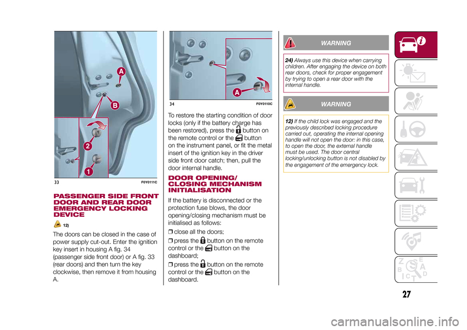
The doors can be closed in the case of
power supply cut-out. Enter the ignition
key insert in housing A fig. 34
(passenger side front door) or A fig. 33
(rear doors) and then turn the key
clockwise, then remove it from housing
A.To restore the starting condition of door
locks (only if the battery charge has
been restored), press the
button on
the remote control or thebutton
on the instrument panel, or fit the metal
insert of the ignition key in the driver
side front door catch; then, pull the
door internal handle.
DOOR OPENING/
CLOSING MECHANISM
INITIALISATIONIf the battery is disconnected or the
protection fuse blows, the door
opening/closing mechanism must be
initialised as follows:
❒close all the doors;
❒press the
button on the remote
control or the
button on the
dashboard;
❒press the
button on the remote
control or the
button on the
dashboard.
WARNING
24)Always use this device when carrying
children. After engaging the device on both
rear doors, check for proper engagement
by trying to open a rear door with the
internal handle.
WARNING
12)If the child lock was engaged and the
previously described locking procedure
carried out, operating the internal opening
handle will not open the door: in this case,
to open the door, the external handle
must be used. The door central
locking/unlocking button is not disabled by
the engagement of the emergency lock.
33
F0Y0111C
34
F0Y0110C
27
9-1-2015 12:9 Pagina 27
PASSENGER SIDE FRONT
DOOR AND REAR DOOR
EMERGENCY LOCKING
DEVICE
12)
Page 35 of 224
IMPORTANT The Dualdrive electric
power steering has an electronic
damping effect while approaching the
end of stroke. In some manoeuvring
conditions, the steering wheel might
rotate a bit before touching its
mechanical stop. This behaviour is
standard as it takes place to prevent
strong impacts on the mechanical
components inside the device.POWER STEERING
ACTIVATION/
DEACTIVATION
33) 34)
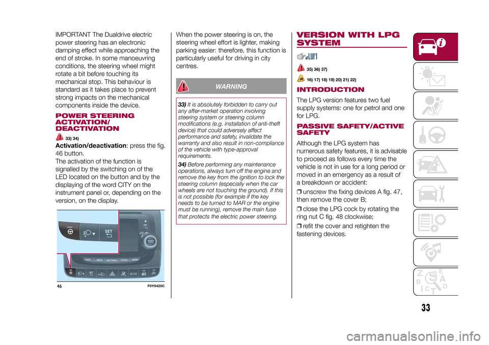
Activation/deactivation: press the fig.
46 button.
The activation of the function is
signalled by the switching on of the
LED located on the button and by the
displaying of the word CITY on the
instrument panel or, depending on the
version, on the display.When the power steering is on, the
steering wheel effort is lighter, making
parking easier: therefore, this function is
particularly useful for driving in city
centres.
WARNING
33)It is absolutely forbidden to carry out
any after-market operation involving
steering system or steering column
modifications (e.g. installation of anti-theft
device) that could adversely affect
performance and safety, invalidate the
warranty and also result in non-compliance
of the vehicle with type-approval
requirements.
34)Before performing any maintenance
operations, always turn off the engine and
remove the key from the ignition to lock the
steering column (especially when the car
wheels are not touching the ground). If this
is not possible (for example if the key
needs to be turned to MAR or the engine
must be running), remove the main fuse
that protects the electric power steering.
VERSION WITH LPG
SYSTEM
35) 36) 37)16) 17) 18) 19) 20) 21) 22)
INTRODUCTIONThe LPG version features two fuel
supply systems: one for petrol and one
for LPG.PASSIVE SAFETY/ACTIVE
SAFETYAlthough the LPG system has
numerous safety features, it is advisable
to proceed as follows every time the
vehicle is not in use for a long period or
moved in an emergency as a result of
a breakdown or accident:
❒unscrew the fixing devices A fig. 47,
then remove the cover B;
❒close the LPG cock by rotating the
ring nut C fig. 48 clockwise;
❒refit the cover and retighten the
fastening devices.
46
F0Y0420C
33
9-1-2015 12:9 Pagina 33
Page 37 of 224
IMPORTANT In order to avoid
inconsistent information by the LPG
gauge on the instrument panel, it is
recommended to refill with at least 10
litres each time.
WARNING
35)Please note that in some countries
(including Italy) there are legal restrictions
in force for parking/garaging motor
vehicles with gas that has a higher density
than air; LPG comes under this category.
36)Do not switch between the two
operating modes whilst starting the engine.
37)If gas is smelled, switch from methane
operation to petrol operation and
immediately go to a Fiat Dealership to have
the vehicle checked and possible system
faults excluded.
WARNING
16)The vehicle is equipped with a gaseous
LPG injection system designed specifically
for it: it is therefore absolutely forbidden
to alter the configuration of the system or
its components. The use of other
components or materials could cause
malfunctions and lead to a reduction
in safety; therefore, in the case of
problems, contact a Fiat Dealership. When
towing or lifting the car, follow the
instructions in the paragraph on "Towing
the car" to prevent damage to the gas
methane system parts.17)The system operates at temperatures
ranging between −20 °C and 100 °C.
18)When painting in an oven, the LPG
tank must be removed from the vehicle and
later refitted by a Fiat Dealership. Although
the LPG system has numerous safety
features, it is advisable to proceed
as follows every time the car is not in use
for a long period or moved in an
emergency as a result of a breakdown or
accident: unscrew the fastening devices of
the LPG tank, then remove it. Close the
LPG cock rotating the ring nut C clockwise
(see "Passive/active Safety"). Refit the
cover and retighten the fastening devices.
19)Only use LPG fuel for motor vehicles.
20)It is strictly forbidden to use any
additive in the LPG. Periodically (at least
once every six months) it is advisable to let
the LPG in the tank run out and, at the
first refuelling, to check that it does not
exceed the maximum capacity of 38.4 litres
(reserve included) (with a tolerance of 2
litres excess). If the level is above 38.4 litres
(reserve included) contact a Fiat
Dealership immediately.
21)When switching from petrol to methane
is requested, a metal noise is heard from
the valves which pressurise the circuit. As a
result of the switching logic described
above, the delay between the ticking of the
valve and the switching off of the warning
on the instrument panel is entirely normal.22)In particular usage conditions, such as
starting and operation at low ambient
temperature or supply of LPG with low
content of propane, the system may
temporarily switch to petrol operation,
without indicating the performed switching
on the instrument panel. In the event of
low LPG levels in the tank or request for
high performance (e.g. overtaking, car fully
laden, steep hills) the system may
automatically switch to petrol operation to
guarantee the engine power requested; the
green warning light on the instrument
panel switches on to indicate this. When
the above conditions are no longer
present, the system automatically restores
LPG operation; the green warning light
switches off. To achieve the above
automatic switching, make sure that there
is enough fuel in the petrol tank.
35
9-1-2015 12:9 Pagina 35
Page 108 of 224
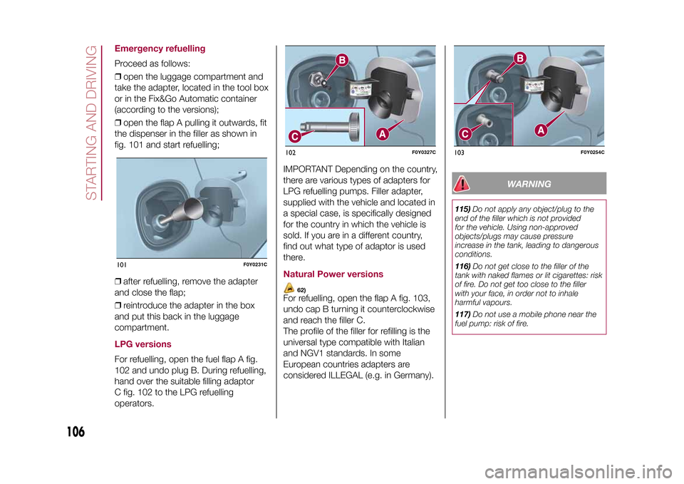
Emergency refuellingProceed as follows:
❒open the luggage compartment and
take the adapter, located in the tool box
or in the Fix&Go Automatic container
(according to the versions);
❒open the flap A pulling it outwards, fit
the dispenser in the filler as shown in
fig. 101 and start refuelling;
❒after refuelling, remove the adapter
and close the flap;
❒reintroduce the adapter in the box
and put this back in the luggage
compartment.LPG versionsFor refuelling, open the fuel flap A fig.
102 and undo plug B. During refuelling,
hand over the suitable filling adaptor
C fig. 102 to the LPG refuelling
operators.IMPORTANT Depending on the country,
there are various types of adapters for
LPG refuelling pumps. Filler adapter,
supplied with the vehicle and located in
a special case, is specifically designed
for the country in which the vehicle is
sold. If you are in a different country,
find out what type of adaptor is used
there.
Natural Power versions
62)
For refuelling, open the flap A fig. 103,
undo cap B turning it counterclockwise
and reach the filler C.
The profile of the filler for refilling is the
universal type compatible with Italian
and NGV1 standards. In some
European countries adapters are
considered ILLEGAL (e.g. in Germany).
WARNING
115)Do not apply any object/plug to the
end of the filler which is not provided
for the vehicle. Using non-approved
objects/plugs may cause pressure
increase in the tank, leading to dangerous
conditions.
116)Do not get close to the filler of the
tank with naked flames or lit cigarettes: risk
of fire. Do not get too close to the filler
with your face, in order not to inhale
harmful vapours.
117)Do not use a mobile phone near the
fuel pump: risk of fire.
101
F0Y0231C
102
F0Y0327C
103
F0Y0254C
106
STARTING AND DRIVING
9-1-2015 12:9 Pagina 106
Page 111 of 224
HAZARD WARNING
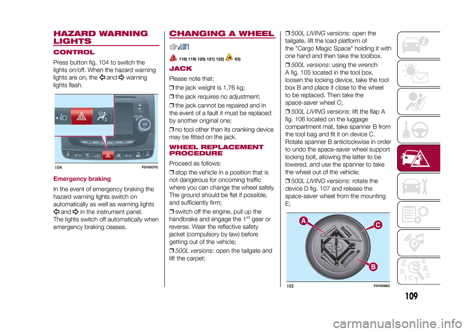
LIGHTSCONTROLPress button fig. 104 to switch the
lights on/off. When the hazard warning
lights are on, the
and
warning
lights flash.
Emergency brakingIn the event of emergency braking the
hazard warning lights switch on
automatically as well as warning lights
and
in the instrument panel.
The lights switch off automatically when
emergency braking ceases.
CHANGING A WHEEL
118) 119) 120) 121) 122)
63)
JACKPlease note that:
❒the jack weight is 1,76 kg;
❒the jack requires no adjustment;
❒the jack cannot be repaired and in
the event of a fault it must be replaced
by another original one;
❒no tool other than its cranking device
may be fitted on the jack.WHEEL REPLACEMENT
PROCEDUREProceed as follows:
❒stop the vehicle in a position that is
not dangerous for oncoming traffic
where you can change the wheel safely.
The ground should be flat if possible,
and sufficiently firm;
❒switch off the engine, pull up the
handbrake and engage the 1
stgear or
reverse. Wear the reflective safety
jacket (compulsory by law) before
getting out of the vehicle;
❒500L versions: open the tailgate and
lift the carpet;❒500L LIVING versions: open the
tailgate, lift the load platform of
the "Cargo Magic Space" holding it with
one hand and then take the toolbox.
❒500L versions: using the wrench
A fig. 105 located in the tool box,
loosen the locking device, take the tool
box B and place it close to the wheel
to be replaced. Then take the
space-saver wheel C;
❒500L LIVING versions: lift the flap A
fig. 106 located on the luggage
compartment mat, take spanner B from
the tool bag and fit it on device C.
Rotate spanner B anticlockwise in order
to undo the space-saver wheel support
locking bolt, allowing the latter to be
lowered, and use the spanner to take
the wheel out of the vehicle;
❒500L LIVING versions: rotate the
device D fig. 107 and release the
space-saver wheel from the mounting
E;
104
F0Y0037C
105
F0Y0096C
109
9-1-2015 12:9 Pagina 109
Page 113 of 224
❒fit the space-saver wheel by inserting
the first stud bolt for two threads into
the hole closest to the valve; then,
tighten the stud bolt by some threads
and proceed in the same way for the
others;
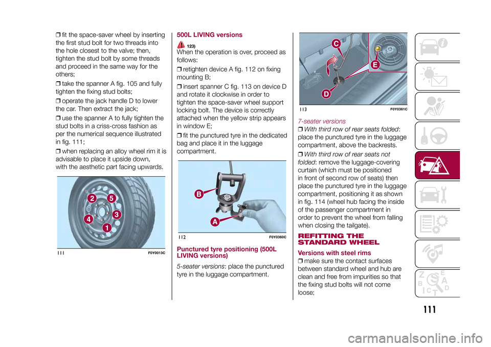
❒take the spanner A fig. 105 and fully
tighten the fixing stud bolts;
❒operate the jack handle D to lower
the car. Then extract the jack;
❒use the spanner A to fully tighten the
stud bolts in a criss-cross fashion as
per the numerical sequence illustrated
in fig. 111;
❒when replacing an alloy wheel rim it is
advisable to place it upside down,
with the aesthetic part facing upwards.
500L LIVING versions
123)
When the operation is over, proceed as
follows:
❒retighten device A fig. 112 on fixing
mounting B;
❒insert spanner C fig. 113 on device D
and rotate it clockwise in order to
tighten the space-saver wheel support
locking bolt. The device is correctly
attached when the yellow strip appears
in window E;
❒fit the punctured tyre in the dedicated
bag and place it in the luggage
compartment.Punctured tyre positioning (500L
LIVING versions)5-seater versions: place the punctured
tyre in the luggage compartment.
7-seater versions❒With third row of rear seats folded:
place the punctured tyre in the luggage
compartment, above the backrests.
❒With third row of rear seats not
folded: remove the luggage-covering
curtain (which must be positioned
in front of second row of seats) then
place the punctured tyre in the luggage
compartment, positioning it as shown
in fig. 114 (wheel hub facing the inside
of the passenger compartment in
order to prevent the wheel from falling
when closing the tailgate).REFITTING THE
STANDARD WHEEL
Versions with steel rims❒make sure the contact surfaces
between standard wheel and hub are
clean and free from impurities so that
the fixing stud bolts will not come
loose;
111
F0Y0013C
112
F0Y0360C
113
F0Y0361C
111
9-1-2015 12:9 Pagina 111
Page 120 of 224
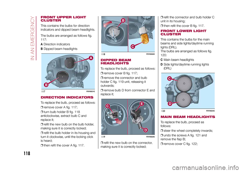
FRONT UPPER LIGHT
CLUSTERThis contains the bulbs for direction
indicators and dipped beam headlights.
The bulbs are arranged as follows fig.
117:A
Direction indicators
B
Dipped beam headlights
DIRECTION INDICATORSTo replace the bulb, proceed as follows:
❒remove cover A fig. 117;
❒turn bulb holder B fig. 118
anticlockwise, extract bulb C and
replace it;
❒refit the new bulb on the bulb holder,
making sure it is correctly locked;
❒refit the bulb holder in its housing and
turn it clockwise, until the locking click
is heard;
❒then refit the cover A fig. 117.
DIPPED BEAM
HEADLIGHTSTo replace the bulb, proceed as follows:
❒remove cover B fig. 117;
❒remove the connector and bulb
holder C fig. 119 unit, releasing it
outwards;
❒remove bulb D from connector E and
replace it;
❒refit the new bulb on the connector,
making sure it is correctly locked;❒refit the connector and bulb holder C
unit in its housing;
❒then refit the cover B fig. 117.
FRONT LOWER LIGHT
CLUSTERThis contains the bulbs for the main
beams and side lights/daytime running
lights (DRL).
The bulbs are arranged as follows fig.
120:C
Main beam headlights
D
Side lights/daytime running lights
(DRL)
MAIN BEAM HEADLIGHTSTo replace the bulb, proceed as
follows:
❒steer the wheel completely inwards;
❒undo the screws A fig. 121 and
remove the flap B;
❒remove cover C fig. 122;
117
F0Y0021C
118
F0Y0022C
119
F0Y0023C
120
F0Y0024C
118
IN AN EMERGENCY
9-1-2015 12:9 Pagina 118
Page 121 of 224
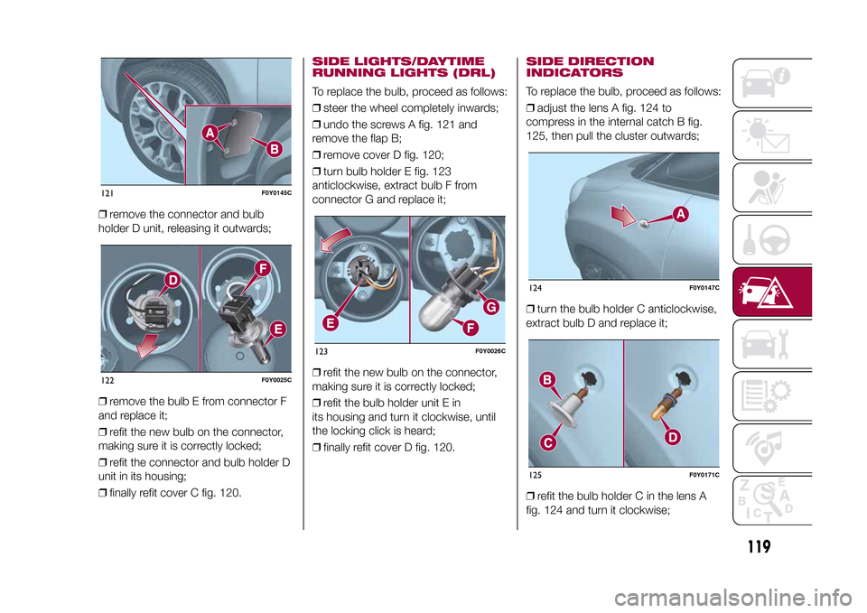
❒remove the connector and bulb
holder D unit, releasing it outwards;
❒remove the bulb E from connector F
and replace it;
❒refit the new bulb on the connector,
making sure it is correctly locked;
❒refit the connector and bulb holder D
unit in its housing;
❒finally refit cover C fig. 120.
SIDE LIGHTS/DAYTIME
RUNNING LIGHTS (DRL)To replace the bulb, proceed as follows:
❒steer the wheel completely inwards;
❒undo the screws A fig. 121 and
remove the flap B;
❒remove cover D fig. 120;
❒turn bulb holder E fig. 123
anticlockwise, extract bulb F from
connector G and replace it;
❒refit the new bulb on the connector,
making sure it is correctly locked;
❒refit the bulb holder unit E in
its housing and turn it clockwise, until
the locking click is heard;
❒finally refit cover D fig. 120.
SIDE DIRECTION
INDICATORSTo replace the bulb, proceed as follows:
❒adjust the lens A fig. 124 to
compress in the internal catch B fig.
125, then pull the cluster outwards;
❒turn the bulb holder C anticlockwise,
extract bulb D and replace it;
❒refit the bulb holder C in the lens A
fig. 124 and turn it clockwise;
121
F0Y0145C
122
F0Y0025C
123
F0Y0026C
124
F0Y0147C
125
F0Y0171C
119
9-1-2015 12:9 Pagina 119