turn signal FIAT 500X 2014 2.G User Guide
[x] Cancel search | Manufacturer: FIAT, Model Year: 2014, Model line: 500X, Model: FIAT 500X 2014 2.GPages: 476, PDF Size: 5.32 MB
Page 108 of 476
LIFTGATE
The liftgate release function is disabled when the ve-
hicle is in motion.
Opening
Opening From Outside
To unlock the liftgate from the outside, squeeze the
electronic liftgate release and pull the liftgate open with
one fluid motion.
When opening the door, the turn signal lights will flash
twice and the interior dome light will illuminate. Theinterior dome light will turn off automatically by clos-
ing the liftgate. Refer to “Interior Lights” in “Getting To
Know Your Vehicle.”
If the liftgate is left open, the interior dome light will
shut off after a few minutes to conserve battery life.
Internal Emergency Release
Proceed as follows:
1. Lower the headrests and fold the seatbacks.
2. Using the supplied screwdriver (located under cargo
floor in tool kit), remove the yellow tab.
Electronic Liftgate Release
1 — Yellow Tab
106 GETTING TO KNOW YOUR VEHICLE
Page 134 of 476
WARNING AND INDICATOR LIGHTS
The warning/indicator lights switch on in the instru-
ment panel together with a dedicated message and/or
acoustic signal when applicable. These indications are
indicative and precautionary and as such must not be
considered as exhaustive and/or alternative to the
information contained in the Owner ’s Manual, which
you are advised to read carefully in all cases. Always
refer to the information in this chapter in the event of a
failure indication.All active telltales will display first if applicable. The
system check menu may appear different based upon
equipment options and current vehicle status. Some
telltales are optional and may not appear.
Red Telltale Indicator Lights
Air Bag Warning Light
Red Telltale
Light What It Means
Air Bag Warning Light
This light will turn on for four to eight seconds as a bulb check when the ignition switch is
first turned to ON/RUN. If the light is either not on during startup, stays on, or turns on
while driving, have the system inspected at an authorized dealer as soon as possible. This
light will illuminate with a single chime when a fault with the Air Bag Warning Light has
been detected, it will stay on until the fault is cleared. If the light comes on intermittently or
remains on while driving, have an authorized dealer service the vehicle immediately. Refer
to “Occupant Restraints” in “Safety” for further information.
132 GETTING TO KNOW YOUR INSTRUMENT PANEL
Page 152 of 476
Electronic Stability Control (ESC) OFF Indicator Light
Yellow TelltaleLight What It Means
Electronic Stability Control (ESC) OFF Indicator Light
This light indicates the Electronic Stability Control (ESC) is off.
Green Telltale Indicator Lights
Turn Signal Indicator Lights
Green Telltale
Light What It Means
Turn Signal Indicator Lights
The instrument cluster arrow will flash independently for the left or right turn signal as se-
lected, as well as the exterior turn signal lamp(s) (front and rear) as selected when the multi-
function lever is moved down (left) or up (right).
150 GETTING TO KNOW YOUR INSTRUMENT PANEL
Page 166 of 476
Enhanced Seat Belt Use Reminder System
(BeltAlert)
Driver And Passenger BeltAlert — If Equipped
BeltAlert is a feature intended to remind the
driver and outboard front seat passenger (if
equipped with outboard front passenger seat
BeltAlert) to buckle their seat belts. The Belt Alert
feature is active whenever the ignition switch is in
the START or ON/RUN position.
Initial Indication
If the driver is unbuckled when the ignition switch is
first in the START or ON/RUN position, a chime will
signal for a few seconds. If the driver or outboard front
seat passenger (if equipped with outboard front passen-
ger seat BeltAlert) is unbuckled when the ignition
switch is first in the START or ON/RUN position the
Seat Belt Reminder Light will turn on and remain on
until both outboard front seat belts are buckled. The
outboard front passenger seat BeltAlert is not active
when an outboard front passenger seat is unoccupied.
BeltAlert Warning Sequence
The BeltAlert warning sequence is activated when the
vehicle is moving above a specified vehicle speed range and the driver or outboard front seat passenger is
unbuckled (if equipped with outboard front passenger
seat BeltAlert) (the outboard front passenger seat
BeltAlert is not active when the outboard front passen-
ger seat is unoccupied). The BeltAlert warning se-
quence starts by blinking the Seat Belt Reminder Light
and sounding an intermittent chime. Once the BeltAlert
warning sequence has completed, the Seat Belt Re-
minder Light will remain on until the seat belts are
buckled. The BeltAlert warning sequence may repeat
based on vehicle speed until the driver and occupied
outboard front seat passenger seat belts are buckled.
The driver should instruct all occupants to buckle their
seat belts.
Change Of Status
If the driver or outboard front seat passenger (if
equipped with outboard front passenger seat BeltAlert)
unbuckles their seat belt while the vehicle is traveling,
the BeltAlert warning sequence will begin until the seat
belts are buckled again.
The outboard front passenger seat BeltAlert is not active
when the outboard front passenger seat is unoccupied.
BeltAlert may be triggered when an animal or other
items are placed on the outboard front passenger seat or
164 SAFETY
Page 187 of 476
Enhanced Accident Response System
In the event of an impact, if the communication net-
work remains intact, and the power remains intact,
depending on the nature of the event, the ORC will
determine whether to have the Enhanced Accident
Response System perform the following functions:
•Cut off fuel to the engine.
• Flash hazard lights as long as the battery has power
or until the hazard light button is pressed. The
hazard lights can be deactivated by pressing the
hazard light button.
• Turn on the interior lights, which remain on as long
as the battery has power or for 15 minutes from the
intervention of the Enhanced Accident Response
System.
• Unlock the power door locks.
• Turn off the Fuel Pump Heater (if equipped).
• Turn off the HVAC Blower Motor.
• Close the HVAC Circulation Door.
Enhanced Accident Response System Reset
Procedure
After the event occurs, when the system is active, a
message regarding fuel cutoff is displayed. Turn the
ignition switch from ignition AVV/START or MAR/
ACC/ON/RUN to ignition STOP/OFF/LOCK. Care-
fully check the vehicle for fuel leaks in the engine
compartment and on the ground near the engine com-
partment and fuel tank before resetting the system and
starting the engine.
Depending on the nature of the event the left and right
turn signal lights, located in the instrument panel, may
both be blinking and will continue to blink. In order to
move your vehicle to the side of the road, you must
follow the system reset procedure.
6
SAFETY 185
Page 188 of 476
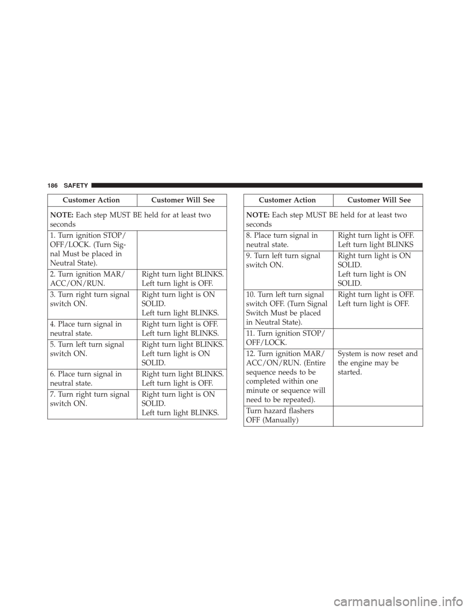
Customer Action Customer Will See
NOTE: Each step MUST BE held for at least two
seconds
1. Turn ignition STOP/
OFF/LOCK. (Turn Sig-
nal Must be placed in
Neutral State).
2. Turn ignition MAR/
ACC/ON/RUN. Right turn light BLINKS.
Left turn light is OFF.
3. Turn right turn signal
switch ON. Right turn light is ON
SOLID.
Left turn light BLINKS.
4. Place turn signal in
neutral state. Right turn light is OFF.
Left turn light BLINKS.
5. Turn left turn signal
switch ON. Right turn light BLINKS.
Left turn light is ON
SOLID.
6. Place turn signal in
neutral state. Right turn light BLINKS.
Left turn light is OFF.
7. Turn right turn signal
switch ON. Right turn light is ON
SOLID.
Left turn light BLINKS.Customer Action Customer Will See
NOTE: Each step MUST BE held for at least two
seconds
8. Place turn signal in
neutral state. Right turn light is OFF.
Left turn light BLINKS
9. Turn left turn signal
switch ON. Right turn light is ON
SOLID.
Left turn light is ON
SOLID.
10. Turn left turn signal
switch OFF. (Turn Signal
Switch Must be placed
in Neutral State). Right turn light is OFF.
Left turn light is OFF.
11. Turn ignition STOP/
OFF/LOCK.
12. Turn ignition MAR/
ACC/ON/RUN. (Entire
sequence needs to be
completed within one
minute or sequence will
need to be repeated). System is now reset and
the engine may be
started.
Turn hazard flashers
OFF (Manually)
186 SAFETY
Page 189 of 476
If a reset procedure step is not completed within 60
seconds, then the turn signal lights will blink and the
reset procedure must be performed again in order to be
successful.
Maintaining Your Air Bag System
WARNING!
•Modifications to any part of the air bag system
could cause it to fail when you need it. You could
be injured if the air bag system is not there to
protect you. Do not modify the components or
wiring, including adding any kind of badges or
stickers to the steering wheel hub trim cover or
the upper right side of the instrument panel. Do
not modify the front bumper, vehicle body struc-
ture, or add aftermarket side steps or running
boards.
• It is dangerous to try to repair any part of the air
bag system yourself. Be sure to tell anyone who
works on your vehicle that it has an air bag
system.
• Do not attempt to modify any part of your air bag
system. The air bag may inflate accidentally or
(Continued)
WARNING! (Continued)
may not function properly if modifications are
made. Take your vehicle to an authorized dealer
for any air bag system service. If your seat,
including your trim cover and cushion, needs to
be serviced in any way (including removal or
loosening/tightening of seat attachment bolts),
take the vehicle to your authorized dealer. Only
manufacturer approved seat accessories may be
used. If it is necessary to modify the air bag
system for persons with disabilities, contact your
authorized dealer.
Event Data Recorder (EDR)
This vehicle is equipped with an event data recorder
(EDR). The main purpose of an EDR is to record, in
certain crash or near crash-like situations, such as an air
bag deployment or hitting a road obstacle, data that will
assist in understanding how a vehicle’s systems per-
formed. The EDR is designed to record data related to
vehicle dynamics and safety systems for a short period
of time, typically 30 seconds or less. The EDR in this
vehicle is designed to record such data as:
•How various systems in your vehicle were operating;
6
SAFETY 187
Page 211 of 476
WARNING!(Continued)
•If the vehicle carpet has been removed and re-
installed, always properly attach carpet to the
floor and check the floor mat fasteners are secure
to the vehicle carpet. Fully depress each pedal to
check for interference with the accelerator, brake,
or clutch pedals then re-install the floor mats.
• It is recommended to only use mild soap and
water to clean your floor mats. After cleaning,
always check your floor mat has been properly
installed and is secured to your vehicle using the
floor mat fasteners by lightly pulling mat.
Periodic Safety Checks You Should Make
Outside The Vehicle
Tires
Examine tires for excessive tread wear and uneven wear
patterns. Check for stones, nails, glass, or other objects
lodged in the tread or sidewall. Inspect the tread for
cuts and cracks. Inspect sidewalls for cuts, cracks, and
bulges. Check the wheel nuts for tightness. Check the
tires (including spare) for proper cold inflation pres-
sure.
Lights
Have someone observe the operation of brake lights
and exterior lights while you work the controls. Check
turn signal and high beam indicator lights on the
instrument panel.
Door Latches
Check for proper closing, latching, and locking.
Fluid Leaks
Check area under vehicle after overnight parking for
fuel, engine coolant, oil, or other fluid leaks. Also, if
gasoline fumes are detected, or if fuel or brake fluid
leaks are suspected, the cause should be located and
corrected immediately.
6
SAFETY 209
Page 249 of 476
ParkSense Sensors
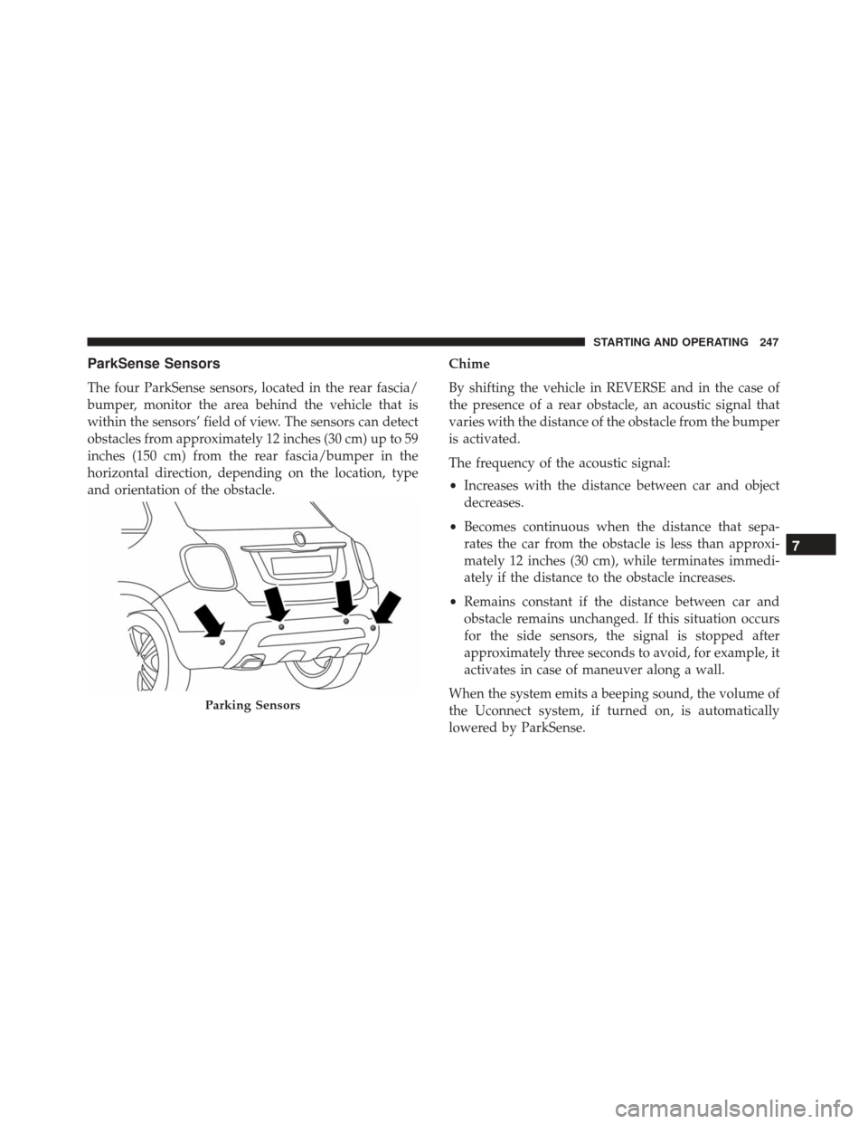
The four ParkSense sensors, located in the rear fascia/
bumper, monitor the area behind the vehicle that is
within the sensors’ field of view. The sensors can detect
obstacles from approximately 12 inches (30 cm) up to 59
inches (150 cm) from the rear fascia/bumper in the
horizontal direction, depending on the location, type
and orientation of the obstacle.Chime
By shifting the vehicle in REVERSE and in the case of
the presence of a rear obstacle, an acoustic signal that
varies with the distance of the obstacle from the bumper
is activated.
The frequency of the acoustic signal:
•
Increases with the distance between car and object
decreases.
• Becomes continuous when the distance that sepa-
rates the car from the obstacle is less than approxi-
mately 12 inches (30 cm), while terminates immedi-
ately if the distance to the obstacle increases.
• Remains constant if the distance between car and
obstacle remains unchanged. If this situation occurs
for the side sensors, the signal is stopped after
approximately three seconds to avoid, for example, it
activates in case of maneuver along a wall.
When the system emits a beeping sound, the volume of
the Uconnect system, if turned on, is automatically
lowered by ParkSense.
Parking Sensors
7
STARTING AND OPERATING 247
Page 253 of 476
CAUTION!(Continued)
above or below the sensors will not be detected
when they are in close proximity.
• The vehicle must be driven slowly when using
ParkSense in order to be able to stop in time
when an obstacle is detected. It is recommended
that the driver looks over his/her shoulder when
using ParkSense.
If it’s necessary to keep the trailer hitch and hitch ball
assembly mounted for a long period, it is possible to
filter out the trailer hitch and hitch ball assembly
presence in sensor field of view. The filtering operation
must be performed only by an authorized dealer.
LANESENSE — IF EQUIPPED
LaneSense Operation
The LaneSense system is operational at speeds above
37 mph (60 km/h) and below 112 mph (180 km/h). The
LaneSense system uses a forward looking camera to
detect lane markings and measure vehicle position
within the lane boundaries. When both lane markings are detected and the driver
unintentionally drifts out of the lane (no turn signal
applied), the LaneSense system provides a haptic warn-
ing in the form of torque applied to the steering wheel
to prompt the driver to remain within the lane bound-
aries. If the driver continues to unintentionally drift out
of the lane, the LaneSense system provides a visual
warning through the instrument cluster display to
prompt the driver to remain within the lane boundaries.
The driver may manually override the haptic warning
by applying torque into the steering wheel at any time.
When only a single lane marking is detected and the
driver unintentionally drifts across the lane marking
(no turn signal applied), the LaneSense system provides
a visual warning through the instrument cluster display
to prompt the driver to remain within the lane. When
only a single lane marking is detected, a haptic (torque)
warning will not be provided.
NOTE:
When operating conditions have been met, the
LaneSense system will monitor if the driver ’s hands are
on the steering wheel and provides an audible warning
to the driver when the driver ’s hands are not detected
on the steering wheel. The system will cancel if the
driver does not return their hands to the wheel.
7
STARTING AND OPERATING 251