FIAT 500X 2014 2.G Owners Manual
500X 2014 2.G
FIAT
FIAT
https://www.carmanualsonline.info/img/10/4525/w960_4525-0.png
FIAT 500X 2014 2.G Owners Manual
Trending: boot, fuel pressure, immobilizer, child restraint, windshield wipers, battery location, transmission fluid
Page 311 of 476
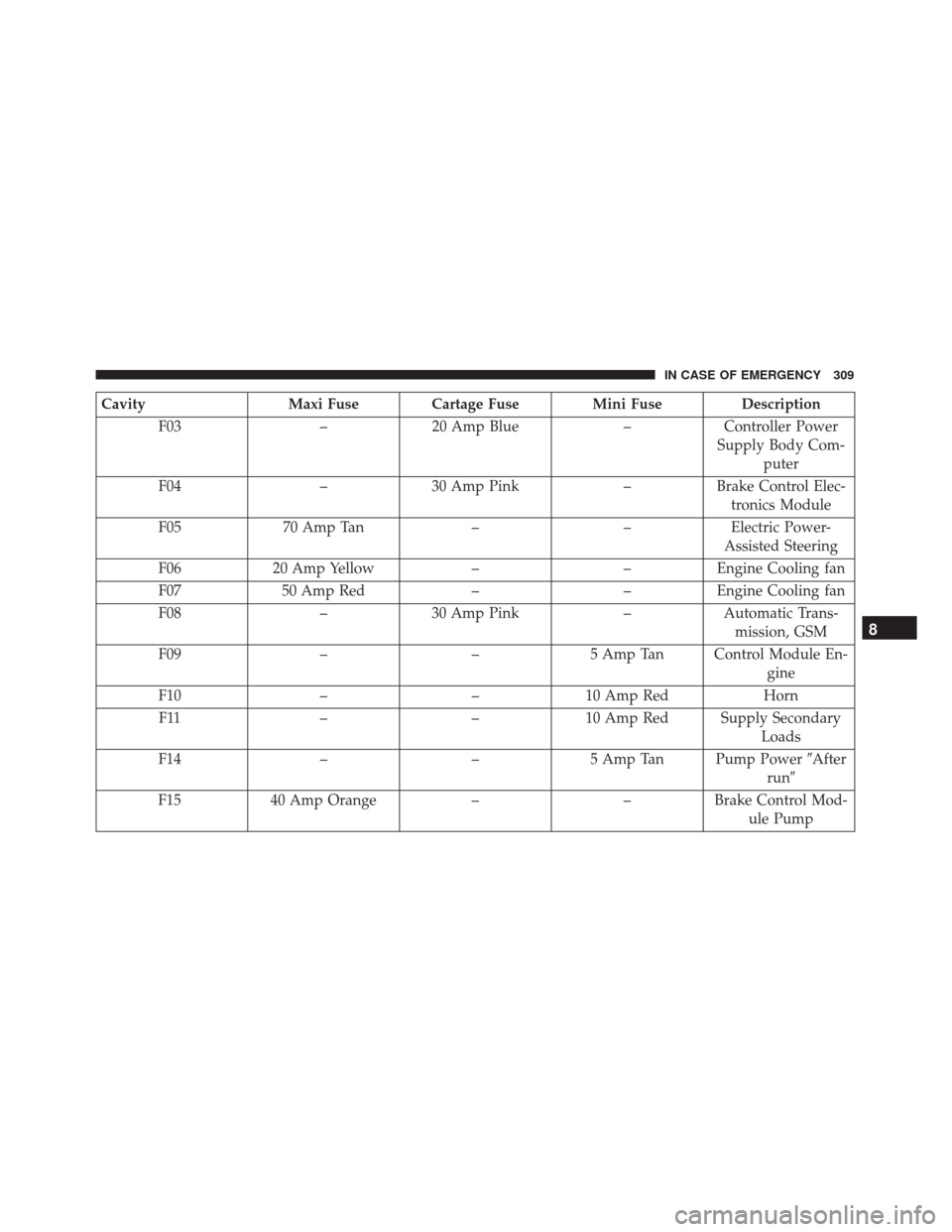
CavityMaxi Fuse Cartage Fuse Mini Fuse Description
F03 –20 Amp Blue –Controller Power
Supply Body Com- puter
F04 –30 Amp Pink –Brake Control Elec-
tronics Module
F05 70 Amp Tan ––Electric Power-
Assisted Steering
F06 20 Amp Yellow ––Engine Cooling fan
F07 50 Amp Red ––Engine Cooling fan
F08 –30 Amp Pink –Automatic Trans-
mission, GSM
F09 ––5 Amp Tan Control Module En-
gine
F10 ––10 Amp Red Horn
F11 ––10 Amp Red Supply Secondary
Loads
F14 ––5 Amp Tan Pump Power �After
run �
F15 40 Amp Orange ––Brake Control Mod-
ule Pump
8
IN CASE OF EMERGENCY 309
Page 312 of 476
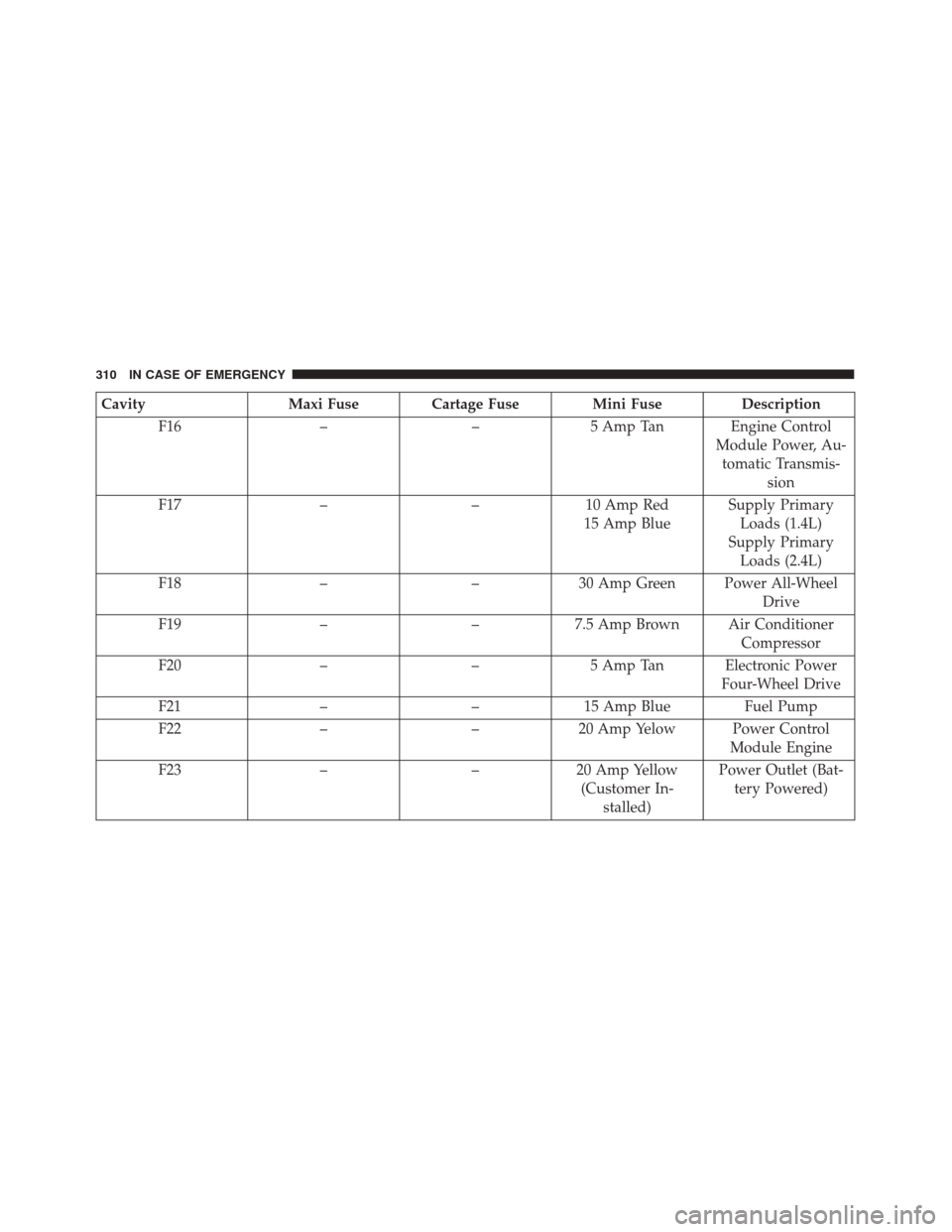
CavityMaxi Fuse Cartage Fuse Mini Fuse Description
F16 ––5 Amp Tan Engine Control
Module Power, Au-tomatic Transmis- sion
F17 ––10 Amp Red
15 Amp Blue Supply Primary
Loads (1.4L)
Supply Primary Loads (2.4L)
F18 ––30 Amp Green Power All-Wheel
Drive
F19 ––7.5 Amp Brown Air Conditioner
Compressor
F20 ––5 Amp Tan Electronic Power
Four-Wheel Drive
F21 ––15 Amp Blue Fuel Pump
F22 ––20 Amp Yelow Power Control
Module Engine
F23 ––20 Amp Yellow
(Customer In- stalled) Power Outlet (Bat-
tery Powered)
310 IN CASE OF EMERGENCY
Page 313 of 476
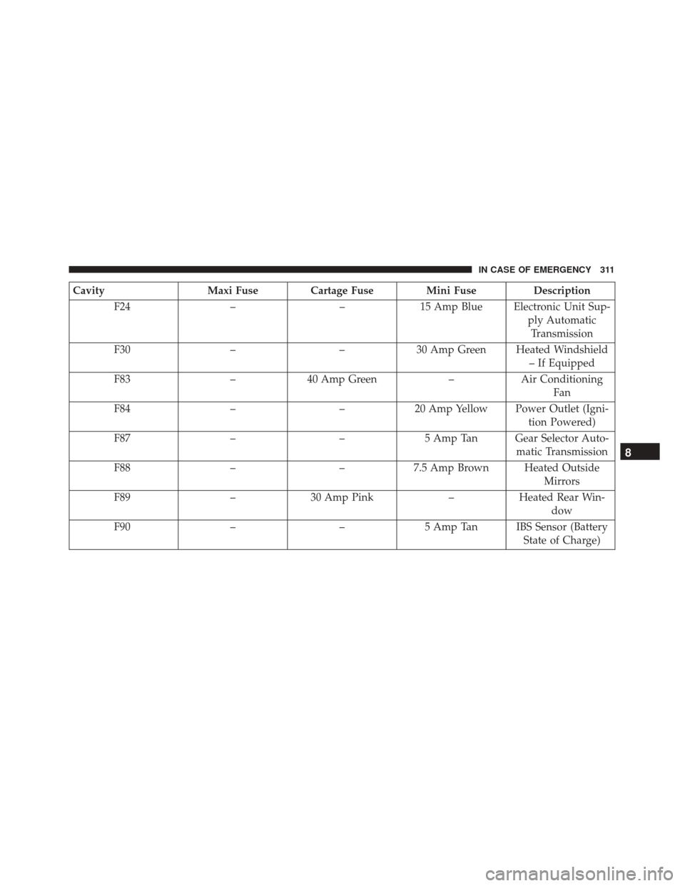
CavityMaxi Fuse Cartage Fuse Mini Fuse Description
F24 ––15 Amp Blue Electronic Unit Sup-
ply AutomaticTransmission
F30 ––30 Amp Green Heated Windshield
– If Equipped
F83 –40 Amp Green –Air Conditioning
Fan
F84 ––20 Amp Yellow Power Outlet (Igni-
tion Powered)
F87 ––5 Amp Tan Gear Selector Auto-
matic Transmission
F88 ––7.5 Amp Brown Heated Outside
Mirrors
F89 –30 Amp Pink –Heated Rear Win-
dow
F90 ––5 Amp Tan IBS Sensor (Battery
State of Charge)
8
IN CASE OF EMERGENCY 311
Page 314 of 476
Body Computer Fuse Center
The controller is located at the left side of the steering
column at the bottom of the instrument panel.
For the fuse replacement see your authorized dealer.
Body Controller Fuse Cavities
312 IN CASE OF EMERGENCY
Page 315 of 476
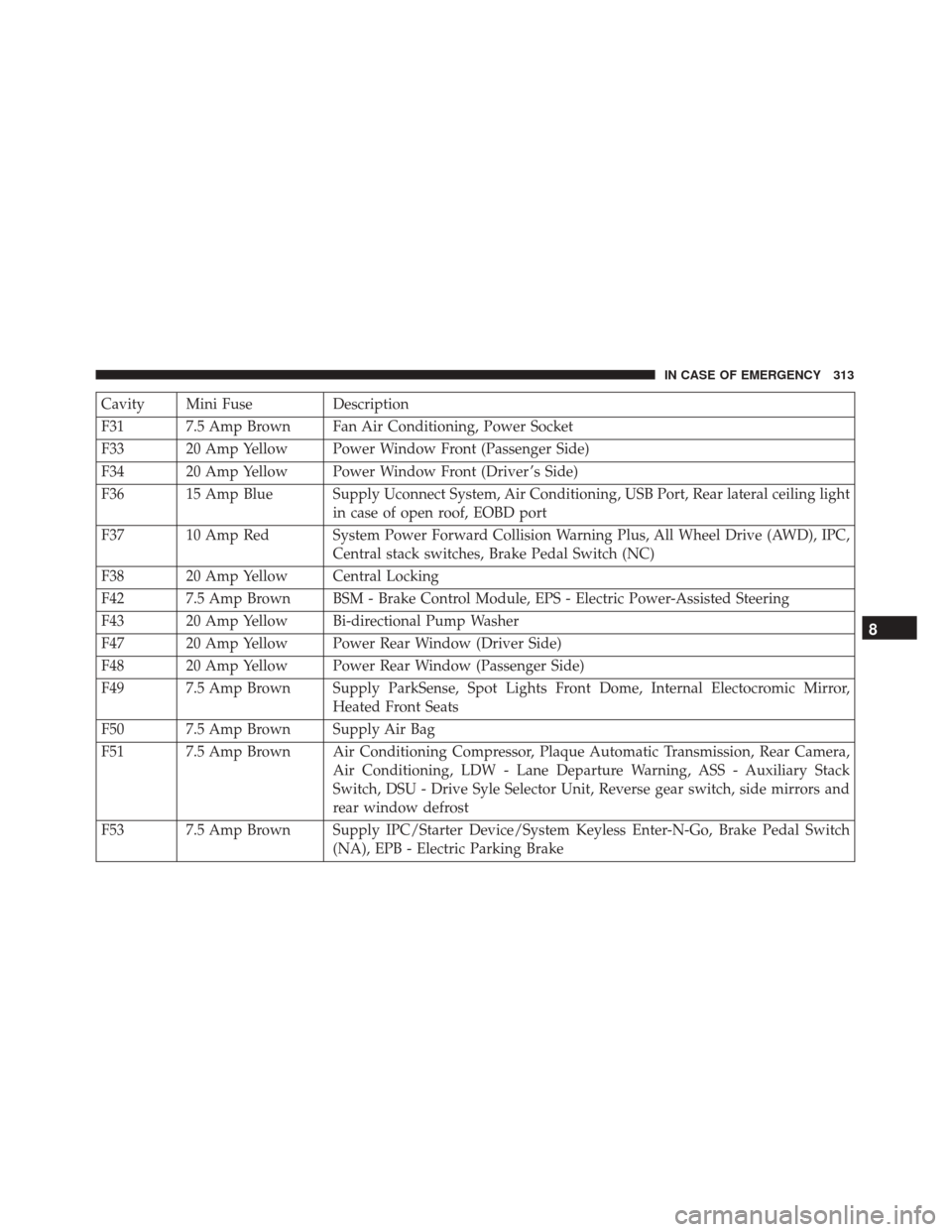
Cavity Mini FuseDescription
F31 7.5 Amp Brown Fan Air Conditioning, Power Socket
F33 20 Amp Yellow Power Window Front (Passenger Side)
F34 20 Amp Yellow Power Window Front (Driver ’s Side)
F36 15 Amp Blue Supply Uconnect System, Air Conditioning, USB Port, Rear lateral ceiling light in case of open roof, EOBD port
F37 10 Amp Red System Power Forward Collision Warning Plus, All Wheel Drive (AWD), IPC, Central stack switches, Brake Pedal Switch (NC)
F38 20 Amp Yellow Central Locking
F42 7.5 Amp Brown BSM - Brake Control Module, EPS - Electric Power-Assisted Steering
F43 20 Amp Yellow Bi-directional Pump Washer
F47 20 Amp Yellow Power Rear Window (Driver Side)
F48 20 Amp Yellow Power Rear Window (Passenger Side)
F49 7.5 Amp Brown Supply ParkSense, Spot Lights Front Dome, Internal Electocromic Mirror, Heated Front Seats
F50 7.5 Amp Brown Supply Air Bag
F51 7.5 Amp Brown Air Conditioning Compressor, Plaque Automatic Transmission, Rear Camera, Air Conditioning, LDW - Lane Departure Warning, ASS - Auxiliary Stack
Switch, DSU - Drive Syle Selector Unit, Reverse gear switch, side mirrors and
rear window defrost
F53 7.5 Amp Brown Supply IPC/Starter Device/System Keyless Enter-N-Go, Brake Pedal Switch (NA), EPB - Electric Parking Brake
8
IN CASE OF EMERGENCY 313
Page 316 of 476
Rear Cargo Fuse/Relay Distribution Unit
To access the fuses, remove the access door from the left
rear panel of the rear cargo area.Push on the left side of the access door to unhinge and
remove.
Cavity
Mini Fuse Description
F2 20 Amp Yellow Audio System
F3 20 Amp Yellow Electric Sunroof
F5 30 Amp Green Power Seat (driver side)
F6 7.5 Amp Brown Power Seat (driver side) Lumbar Adjustment
F8 20 Amp Yellow Heating Front Seats
Access Door Location
Rear Cargo Fuse Cavities
314 IN CASE OF EMERGENCY
Page 317 of 476
JACKING AND TIRE CHANGING
WARNING!
•Do not attempt to change a tire on the side of the
vehicle close to moving traffic. Pull far enough off
the road to avoid the danger of being hit when
operating the jack or changing the wheel.
• Being under a jacked-up vehicle is dangerous.
The vehicle could slip off the jack and fall on you.
You could be crushed. Never put any part of your
body under a vehicle that is on a jack. If you need
to get under a raised vehicle, take it to a service
center where it can be raised on a lift.
• Never start or run the engine while the vehicle is
on a jack.
• The jack is designed to be used as a tool for
changing tires only. The jack should not be used
to lift the vehicle for service purposes. The ve-
hicle should be jacked on a firm level surface
only. Avoid ice or slippery areas.
Jack Location/Spare Tire Stowage — If
Equipped
The jack and tools are located in the rear storage
compartment if equipped, inside a special container.
1. Open the liftgate.
Jack And Tools Location
8
IN CASE OF EMERGENCY 315
Page 318 of 476
2. Lift the access cover using the load floor handle. 3. Remove the fastener securing the spare tire.
Load Floor HandleSpare Tire Fastener
316 IN CASE OF EMERGENCY
Page 319 of 476
4. Remove the jack, wheel bolt wrench, and wheelchocks.
5. Remove the spare tire.WARNING!
A loose tire or jack thrown forward in a collision or
hard stop could endanger the occupants of the
vehicle. Always stow the jack parts and the spare
tire in the places provided. Have the deflated (flat)
tire repaired or replaced immediately.
Preparations For Jacking
1. Park the vehicle on a firm level surface as far from the edge of the roadway as possible. Avoid icy or
slippery areas.
WARNING!
Do not attempt to change a tire on the side of the
vehicle close to moving traffic, pull far enough off
the road to avoid being hit when operating the jack
or changing the wheel.
2. Turn on the Hazard Warning flasher.
3. Set the Electric Park Brake.
4. Place the gear selector into PARK (automatic trans- mission) or REVERSE (manual transmission).
Jack And Tools
1 — Wheel Bolt Wrench
2 — Jack
3 — Emergency Funnel
4 — Wheel Chock
5 — Screwdriver
6 — Emergency Allen Key
8
IN CASE OF EMERGENCY 317
Page 320 of 476
5. Turn the ignition to STOP mode.
6. Chock both the front and rear of the wheel diago-nally opposite of the jacking posi-
tion. For example, if changing the
right front tire, chock the left rear
wheel.
NOTE: Passengers should not remain in the vehicle
when the vehicle is being jacked.
Jacking Instructions
WARNING!
Carefully follow these tire changing warnings to
help prevent personal injury or damage to your
vehicle:
• Always park on a firm, level surface as far from
the edge of the roadway as possible before raising
the vehicle.
• Turn on the Hazard Warning flasher.
• Chock the wheel diagonally opposite the wheel to
be raised.
• Apply the parking brake and place an automatic
transmission in PARK.
(Continued)
WARNING! (Continued)
•Never start or run the engine with the vehicle on
a jack.
• Do not let anyone sit in the vehicle when it is on
a jack.
• Do not get under the vehicle when it is on a jack.
If you need to get under a raised vehicle, take it to
a service center where it can be raised on a lift.
• Only use the jack in the positions indicated and
for lifting this vehicle during a tire change.
• If working on or near a roadway, be extremely
careful of motor traffic.
• To assure that spare tires, flat or inflated, are
securely stowed, spares must be stowed with the
valve stem facing the ground.
318 IN CASE OF EMERGENCY
Trending: key, coolant, brakes, warning, alternator, mirror, key fob battery
