FIAT 500X 2015 2.G Owners Manual
Manufacturer: FIAT, Model Year: 2015, Model line: 500X, Model: FIAT 500X 2015 2.GPages: 240, PDF Size: 10.72 MB
Page 121 of 240
REFUELLING THE
VEHICLE
122) 123) 124)
PETROL ENGINESOnly use unleaded petrol with a number
of octanes (R.O.N.) not lower than 95
(EN 228 specification).DIESEL ENGINES
50)
Only use Diesel for motor vehicles (EN
590 specification).
When using or parking the vehicle for a
long time in the mountains or cold
areas, it is advisable to refuel using
locally available diesel. In this case, it is
also advisable to keep the tank over
50% full.REFUELLING
PROCEDURE"Capless Fuel" is a device at the
opening for the fuel tank which opens
and recloses automatically when the
fuel supply gun is introduced/removed.
The "Capless Fuel" device is provided
with an inhibitor which prevents
refuelling with incorrect fuel.
Opening the flapTo refuel proceed as follows:
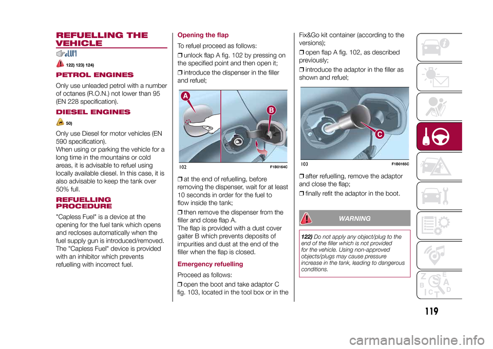
❒unlock flap A fig. 102 by pressing on
the specified point and then open it;
❒introduce the dispenser in the filler
and refuel;
❒at the end of refuelling, before
removing the dispenser, wait for at least
10 seconds in order for the fuel to
flow inside the tank;
❒then remove the dispenser from the
filler and close flap A.
The flap is provided with a dust cover
gaiter B which prevents deposits of
impurities and dust at the end of the
filler when the flap is closed.Emergency refuellingProceed as follows:
❒open the boot and take adaptor C
fig. 103, located in the tool box or in theFix&Go kit container (according to the
versions);
❒open flap A fig. 102, as described
previously;
❒introduce the adaptor in the filler as
shown and refuel;
❒after refuelling, remove the adaptor
and close the flap;
❒finally refit the adaptor in the boot.
WARNING
122)Do not apply any object/plug to the
end of the filler which is not provided
for the vehicle. Using non-approved
objects/plugs may cause pressure
increase in the tank, leading to dangerous
conditions.
102
F1B0164C
103
F1B0165C
119
15-12-2014 8:23 Pagina 119
Page 122 of 240
123)Do not get close to the filler of the
tank with naked flames or lit cigarettes: risk
of fire. Do not get too close to the filler
with your face, in order not to inhale
harmful vapours.
124)Do not use a mobile phone near the
fuel pump: risk of fire.
WARNING
50)Vehicles with a diesel engine must only
be filled with diesel fuel for motor vehicles,
in compliance with European Standard
EN 590. The use of other products or
mixtures may damage the engine beyond
repair and consequently invalidate the
warranty, due to the damage caused. If
you accidentally refuel with another type of
fuel, do not start the engine, and drain
the tank. If the engine has run, even for a
very short time, you will need to have
the entire fuel supply system emptied in
addition to the tank.
120
STARTING AND DRIVING
15-12-2014 8:23 Pagina 120
Page 123 of 240
IN AN EMERGENCY
A punctured tyre or a burnt-out bulb?
At times, a problem may interfere
with our journey.
The pages on emergencies can help
you to deal with critical situations
independently and with calm.
In an emergency we recommend that
you call the freephone number found in
the Warranty Booklet.
It is also possible to call the national or
international universal freephone
number to search for the nearest Fiat
Dealership.HAZARD WARNING LIGHTS...........122
BULB REPLACEMENT....................122
REPLACING FUSES........................128
CHANGING A WHEEL ....................133
FIX&GO AUTOMATIC KIT ................136
EMERGENCY STARTING ................138
FUEL CUT-OFF SYSTEM ................140
AUTOMATIC TRANSMISSION
GEAR LEVER UNLOCKING.............140
TOWING THE VEHICLE ..................142
121
15-12-2014 8:23 Pagina 121
Page 124 of 240
HAZARD WARNING
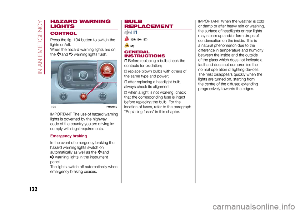
LIGHTSCONTROLPress the fig. 104 button to switch the
lights on/off.
When the hazard warning lights are on,
the
and
warning lights flash.
IMPORTANT The use of hazard warning
lights is governed by the highway
code of the country you are driving in:
comply with legal requirements.
Emergency brakingIn the event of emergency braking the
hazard warning lights switch on
automatically as well as the
and
warning lights in the instrument
panel.
The lights switch off automatically when
emergency braking ceases.
BULB
REPLACEMENT
125) 126) 127)51)
GENERAL
INSTRUCTIONS❒Before replacing a bulb check the
contacts for oxidation;
❒replace blown bulbs with others of
the same type and power;
❒after replacing a headlight bulb,
always check its alignment;
❒when a light is not working, check
that the corresponding fuse is intact
before replacing the bulb. For the
location of fuses, refer to the paragraph
“Replacing fuses” in this chapter.IMPORTANT When the weather is cold
or damp or after heavy rain or washing,
the surface of headlights or rear lights
may steam up and/or form drops of
condensation on the inside. This is
a natural phenomenon due to the
difference in temperature and humidity
between the inside and the outside
of the glass which does not indicate a
fault and does not compromise the
normal operation of lighting devices.
The mist disappears quickly when the
lights are turned on, starting from
the centre of the diffuser, extending
progressively towards the edges.
104
F1B0185C
122
IN AN EMERGENCY
15-12-2014 8:23 Pagina 122
Page 125 of 240
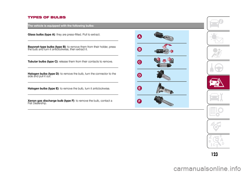
TYPES OF BULBSThe vehicle is equipped with the following bulbs:Glass bulbs (type A): they are press-fitted. Pull to extract.Bayonet-type bulbs (type B): to remove them from their holder, press
the bulb and turn it anticlockwise, then extract it.
Tubular bulbs (type C): release them from their contacts to remove.
Halogen bulbs (type D): to remove the bulb, turn the connector to the
side and pull it out.
Halogen bulbs (type E): to remove the bulb, turn it anticlockwise.
Xenon gas discharge bulb (type F): to remove the bulb, contact a
Fiat Dealership.
123
15-12-2014 8:23 Pagina 123
Page 126 of 240
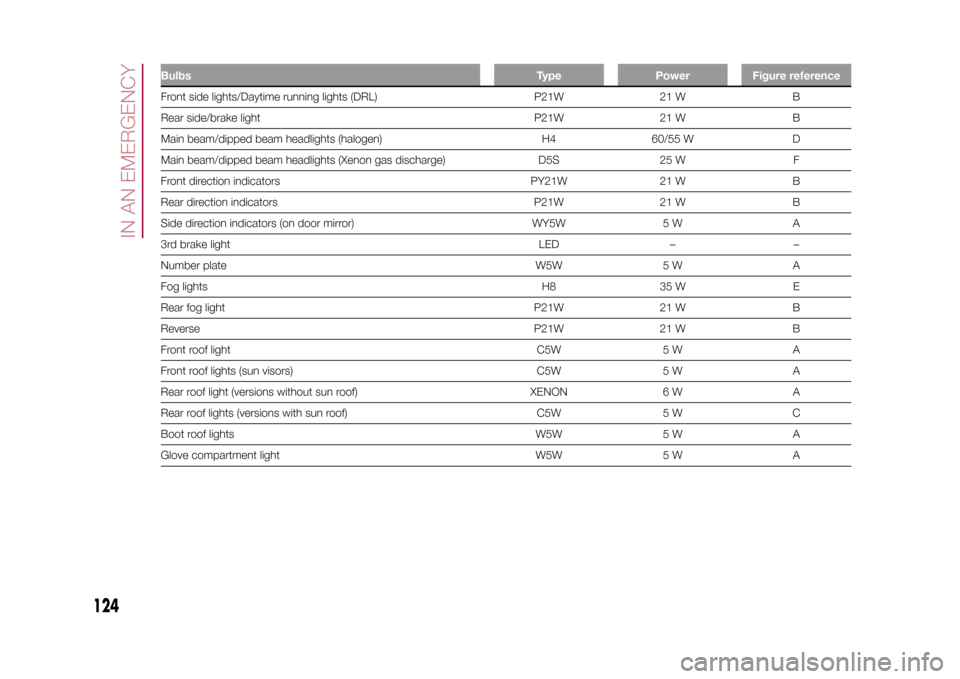
Bulbs Type Power Figure referenceFront side lights/Daytime running lights (DRL) P21W 21 W B
Rear side/brake light P21W 21 W B
Main beam/dipped beam headlights (halogen) H4 60/55 W D
Main beam/dipped beam headlights (Xenon gas discharge) D5S 25 W F
Front direction indicators PY21W 21 W B
Rear direction indicators P21W 21 W B
Side direction indicators (on door mirror) WY5W 5 W A
3rd brake light LED – –
Number plate W5W 5 W A
Fog lights H8 35 W E
Rear fog light P21W 21 W B
Reverse P21W 21 W B
Front roof light C5W 5 W A
Front roof lights (sun visors) C5W 5 W A
Rear roof light (versions without sun roof) XENON 6 W A
Rear roof lights (versions with sun roof) C5W 5 W C
Boot roof lights W5W 5 W A
Glove compartment light W5W 5 W A
124
IN AN EMERGENCY
15-12-2014 8:23 Pagina 124
Page 127 of 240
REPLACING AN
EXTERNAL BULB
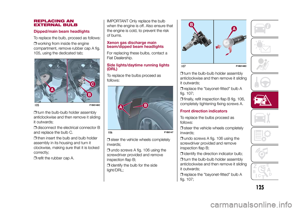
Dipped/main beam headlightsTo replace the bulb, proceed as follows:
❒working from inside the engine
compartment, remove rubber cap A fig.
105, using the dedicated tab;
❒turn the bulb-bulb holder assembly
anticlockwise and then remove it sliding
it outwards;
❒disconnect the electrical connector B
and replace the bulb C.
❒then insert the bulb and bulb holder
assembly in its housing and turn it
clockwise, making sure that it is locked
correctly;
❒refit the rubber cap A.IMPORTANT Only replace the bulb
when the engine is off. Also ensure that
the engine is cold, to prevent the risk
of burns.
Xenon gas discharge main
beam/dipped beam headlightsFor replacing these bulbs, contact a
Fiat Dealership.Side lights/daytime running lights
(DRL)To replace the bulbs proceed as
follows:
❒steer the vehicle wheels completely
inwards;
❒undo screws A fig. 106 using the
screwdriver provided and remove
inspection flap B;
❒identify the bulb for the side
light/DRL;❒turn the bulb-bulb holder assembly
anticlockwise and then remove it sliding
it outwards;
❒replace the "bayonet-fitted" bulb A
fig. 107;
❒finally, refit inspection flap B fig. 106,
completely tightening fixing screws A.
Front direction indicatorsTo replace the bulbs proceed as
follows:
❒steer the vehicle wheels completely
inwards;
❒undo screws A fig. 106 using the
screwdriver provided and remove
inspection flap B;
❒identify the direction indicator bulb;
❒turn the bulb-bulb holder assembly
anticlockwise and then remove it sliding
it outwards;
❒replace the "bayonet-fitted" bulb A
fig. 107;
105
F1B0146C
106
F1B0147
107
F1B0148C
125
15-12-2014 8:23 Pagina 125
Page 128 of 240
❒finally, refit inspection flap B fig. 106,
completely tightening fixing screws A.Fog lightsTo replace the bulbs proceed as
follows:
❒steer the vehicle wheels completely
inwards;
❒undo screws A fig. 106 using the
screwdriver provided and remove
inspection flap B;
❒identify the fog light bulb;
❒turn the bulb-bulb holder assembly
anticlockwise and then remove it sliding
it outwards;
❒disconnect the electrical connector;
❒replace the bulb-bulb holder
assembly B fig. 107.
❒reconnect the electrical connector to
the new bulb-bulb holder assembly,
then fit it ensuring that it locks correctly;
❒fit the assembly turning it clockwise,
ensuring that it locks correctly;
❒finally, refit inspection flap B fig. 106,
completely tightening fixing screws A.Side direction indicatorsIMPORTANT The procedure is only
described by way of illustration. It
is advisable to contact a Fiat Dealership
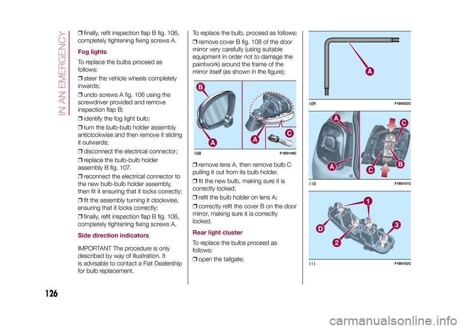
for bulb replacement.To replace the bulb, proceed as follows:
❒remove cover B fig. 108 of the door
mirror very carefully (using suitable
equipment in order not to damage the
paintwork) around the frame of the
mirror itself (as shown in the figure);
❒remove lens A, then remove bulb C
pulling it out from its bulb holder.
❒fit the new bulb, making sure it is
correctly locked;
❒refit the bulb holder on lens A;
❒correctly refit the cover B on the door
mirror, making sure it is correctly
locked.
Rear light clusterTo replace the bulbs proceed as
follows:
❒open the tailgate;108
F1B0149C
109
F1B0022C
110
F1B0151C
111
F1B0152C
126
IN AN EMERGENCY
15-12-2014 8:23 Pagina 126
Page 129 of 240
❒use the wrench A fig. 109 supplied
with the vehicle (located inside the case
with the on-board documentation),
undo the two screws A fig. 110, then
release the light cluster from the
relevant pin fastenings, pulling
cautiously;
❒disconnect the central connector B,
then undo the two screws C;
❒release the tabs indicated by the
arrows and extract the bulb holder
assembly D fig. 111;
❒identify the bulb to be replaced (1
Side/Stop - 2 Direction indicator -
3 Rear fog light or Reverse);
❒all bulbs are "bayonet-fitted";
therefore they must be lightly pressed
and simultaneously turned to be
replaced: anticlockwise for extraction,
clockwise for fitting;
❒correctly refit the bulb holder
assembly D in the light casing; stop
when you hear that the tabs click into
place;
❒tighten the two screws C fig. 110 and
reconnect the central connector B;
❒refit the lens unit, fully tightening the
two screws A;
❒reclose the tailgate.
3rd
brake lights
The 3
rd
brake lights are LED-based. For
their replacement, contact a Fiat
Dealership.
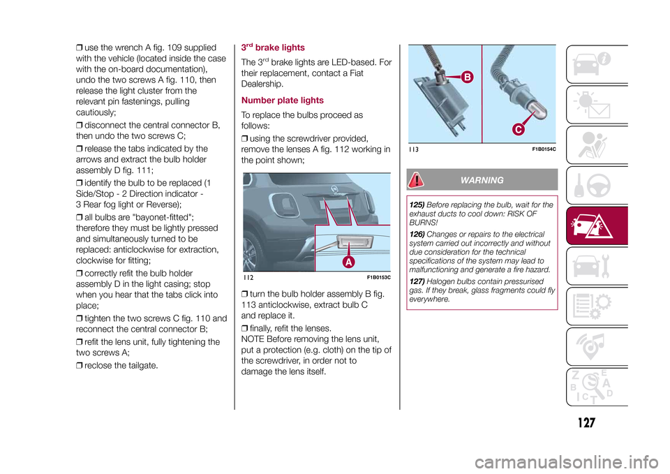
Number plate lightsTo replace the bulbs proceed as
follows:
❒using the screwdriver provided,
remove the lenses A fig. 112 working in
the point shown;
❒turn the bulb holder assembly B fig.
113 anticlockwise, extract bulb C
and replace it.
❒finally, refit the lenses.
NOTE Before removing the lens unit,
put a protection (e.g. cloth) on the tip of
the screwdriver, in order not to
damage the lens itself.
WARNING
125)Before replacing the bulb, wait for the
exhaust ducts to cool down: RISK OF
BURNS!
126)Changes or repairs to the electrical
system carried out incorrectly and without
due consideration for the technical
specifications of the system may lead to
malfunctioning and generate a fire hazard.
127)Halogen bulbs contain pressurised
gas. If they break, glass fragments could fly
everywhere.
112
F1B0153C
113
F1B0154C
127
15-12-2014 8:23 Pagina 127
Page 130 of 240
WARNING
51)Halogen bulbs must be handled by
holding the metallic part only. Touching the
transparent part of the bulb with your
fingers may reduce the intensity of the
emitted light and even reduce the lifespan
of the bulb. In the case of accidental
contact, rub the lamp with a cloth and
alcohol and leave to dry.
REPLACING FUSESINTRODUCTION
128) 129) 130) 131)52) 53)
Fuses protect the electrical system:
they intervene (blow) in the event of a
failure or improper action on the
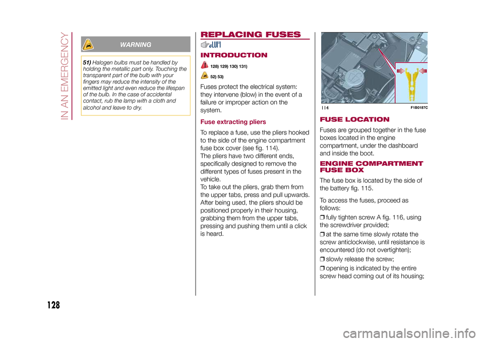
system.Fuse extracting pliersTo replace a fuse, use the pliers hooked
to the side of the engine compartment
fuse box cover (see fig. 114).
The pliers have two different ends,
specifically designed to remove the
different types of fuses present in the
vehicle.
To take out the pliers, grab them from
the upper tabs, press and pull upwards.
After being used, the pliers should be
positioned properly in their housing,
grabbing them from the upper tabs,
pressing and pushing them until a click
is heard.
FUSE LOCATIONFuses are grouped together in the fuse
boxes located in the engine
compartment, under the dashboard
and inside the boot.ENGINE COMPARTMENT
FUSE BOXThe fuse box is located by the side of
the battery fig. 115.
To access the fuses, proceed as
follows:
❒fully tighten screw A fig. 116, using
the screwdriver provided;
❒at the same time slowly rotate the
screw anticlockwise, until resistance is
encountered (do not overtighten);
❒slowly release the screw;
❒opening is indicated by the entire
screw head coming out of its housing;114
F1B0187C
128
IN AN EMERGENCY
15-12-2014 8:23 Pagina 128