diagram FIAT 500X 2015 2.G Owners Manual
[x] Cancel search | Manufacturer: FIAT, Model Year: 2015, Model line: 500X, Model: FIAT 500X 2015 2.GPages: 240, PDF Size: 10.72 MB
Page 106 of 240

MANUAL GEARBOX
110)37)
To engage the gears, press the clutch
pedal fully and put the gear lever into
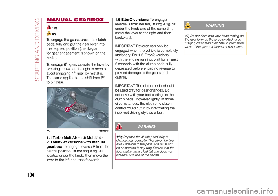
the required position (the diagram
for gear engagement is shown on the
knob ).
To engage 6
th
gear, operate the lever by
pressing it towards the right in order to
avoid engaging 4
th
gear by mistake.
The same applies to the shift from 6
th
to 5
th
gear.
1.4 Turbo MultiAir - 1.6 MultiJet -
2.0 MultiJet versions with manual
gearbox:To engage reverse R from the
neutral position, lift the ring A fig. 90
located under the knob, then move the
lever to the left and then forwards.1.6 E.torQ versions:To engage
reverse R from neutral, lift ring A fig. 90
under the knob and at the same time
move the lever to the right and then
backwards.
IMPORTANT Reverse can only be
engaged when the vehicle is completely
stationary. For 1.6 E.torQ versions:
with the engine running, wait for at least
2 seconds with the clutch pedal fully
depressed before engaging reverse to
prevent damage to the gears and
grating.
IMPORTANT The clutch pedal should
be used only for gear changes. Do
not drive with your foot resting on the
clutch pedal, however lightly. In some
circumstances, the electronic clutch
control could cut in by interpreting the
incorrect driving style as a fault.
WARNING
110)Depress the clutch pedal fully to
change gear correctly. Therefore, the floor
area underneath the pedal unit must not
be obstructed in any way. Ensure that the
floor mat is always laid flat and does not
interfere with use of the pedals.
WARNING
37)Do not drive with your hand resting on
the gear lever as the force exerted, even
if slight, could lead over time to premature
wear of the gearbox internal components.
90
F1B0134C
104
STARTING AND DRIVING
12-1-2015 15:6 Pagina 104
Page 120 of 240

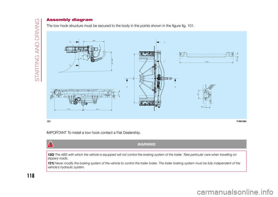
Assembly diagramThe tow hook structure must be secured to the body in the points shown in the figure fig. 101.
.
IMPORTANT To install a tow hook contact a Fiat Dealership.
WARNING
120)The ABS with which the vehicle is equipped will not control the braking system of the trailer. Take particular care when travelling on
slippery roads.
121)Never modify the braking system of the vehicle to control the trailer brake. The trailer braking system must be fully independent of the
vehicle’s hydraulic system.101
F1B0168C
118
STARTING AND DRIVING
15-12-2014 8:23 Pagina 118
Page 135 of 240

CHANGING A WHEELJACKPlease note that:
❒the weight of the jack is 2.8 kg;
❒The jack requires no adjustment;
❒the jack cannot be repaired and in
the event of a fault it must be replaced
by another original one;
❒No tool other than its cranking device
may be fitted on the jack.CHANGING PROCEDURE
132) 133) 134) 135) 136) 137) 138) 139)
Proceed as follows:
❒stop the vehicle in a position that is
not dangerous for oncoming traffic
where you can change the wheel safely.
The ground should be flat if possible,
and sufficiently firm;
❒stop the engine, engage the hazard
warning lights and the electric parking
brake;
❒engage first gear or reverse or, for
versions with automatic transmission,
move the lever to position P (Park);
❒wear the reflective safety jacket
(compulsory by law in certain countries)
before getting out of the vehicle;❒open the boot and position the
reconfigurable load platform in
an inclined position (see "Boot" in the
"Knowing your vehicle" chapter);
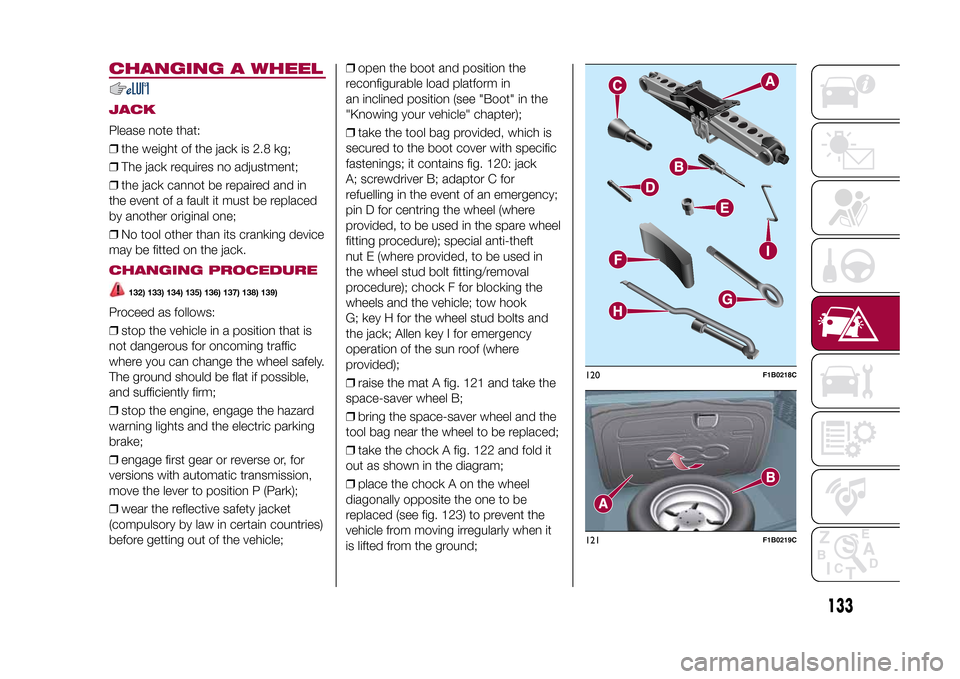
❒take the tool bag provided, which is
secured to the boot cover with specific
fastenings; it contains fig. 120: jack
A; screwdriver B; adaptor C for
refuelling in the event of an emergency;
pin D for centring the wheel (where
provided, to be used in the spare wheel
fitting procedure); special anti-theft
nut E (where provided, to be used in
the wheel stud bolt fitting/removal
procedure); chock F for blocking the
wheels and the vehicle; tow hook
G; key H for the wheel stud bolts and
the jack; Allen key I for emergency
operation of the sun roof (where
provided);
❒raise the mat A fig. 121 and take the
space-saver wheel B;
❒bring the space-saver wheel and the
tool bag near the wheel to be replaced;
❒take the chock A fig. 122 and fold it
out as shown in the diagram;
❒place the chock A on the wheel
diagonally opposite the one to be
replaced (see fig. 123) to prevent the
vehicle from moving irregularly when it
is lifted from the ground;
120
F1B0218C
121
F1B0219C
133
15-12-2014 8:23 Pagina 133