warning FIAT 500X 2018 Owner handbook (in English)
[x] Cancel search | Manufacturer: FIAT, Model Year: 2018, Model line: 500X, Model: FIAT 500X 2018Pages: 276, PDF Size: 7.08 MB
Page 25 of 276
STEERING WHEEL
15) 16)
ADJUSTMENTS
The steering wheel can be adjusted
both in height and axially.
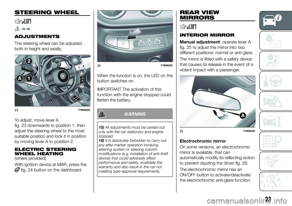
To adjust, move lever A
fig. 23 downwards to position 1, then
adjust the steering wheel to the most
suitable position and lock it in position
by moving lever A to position 2.
ELECTRIC STEERING
WHEEL HEATING
(where provided)
With ignition device at MAR, press the
fig. 24 button on the dashboard.When the function is on, the LED on the
button switches on.
IMPORTANT The activation of this
function with the engine stopped could
flatten the battery.
WARNING
15)
All adjustments must be carried out
only with the car stationary and engine
stopped.
16) It is absolutely forbidden to carry out
any after-market operation involving
steering system or steering column
modifications (e.g. installation of anti-theft
device) that could adversely affect
performance and safety, invalidate the
warranty and also result in the car not
meeting type-approval requirements.
REAR VIEW
MIRRORS
INTERIOR MIRROR
Manual adjustment: operate lever A
fig. 25 to adjust the mirror into two
different positions: normal or anti-glare.
The mirror is fitted with a safety device
that causes its release in the event of a
violent impact with a passenger.
Electrochromic mirror
On some versions, an electrochromic
mirror is available, that can
automatically modify its reflecting action
to prevent dazzling the driver fig. 26.
The electrochromic mirror has an
ON/OFF button to activate/deactivate
the electrochromic anti-glare function.
23F1B0628C
24F1B0625C
25F1B0033C
23
Page 27 of 276
Mirrors realignment operation
In case one of the door mirrors has
been moved manually it may occur that
the mirror itself does not retain its
position in a stable way while driving.
In that case it is necessary to carry out
the following realignment operation:
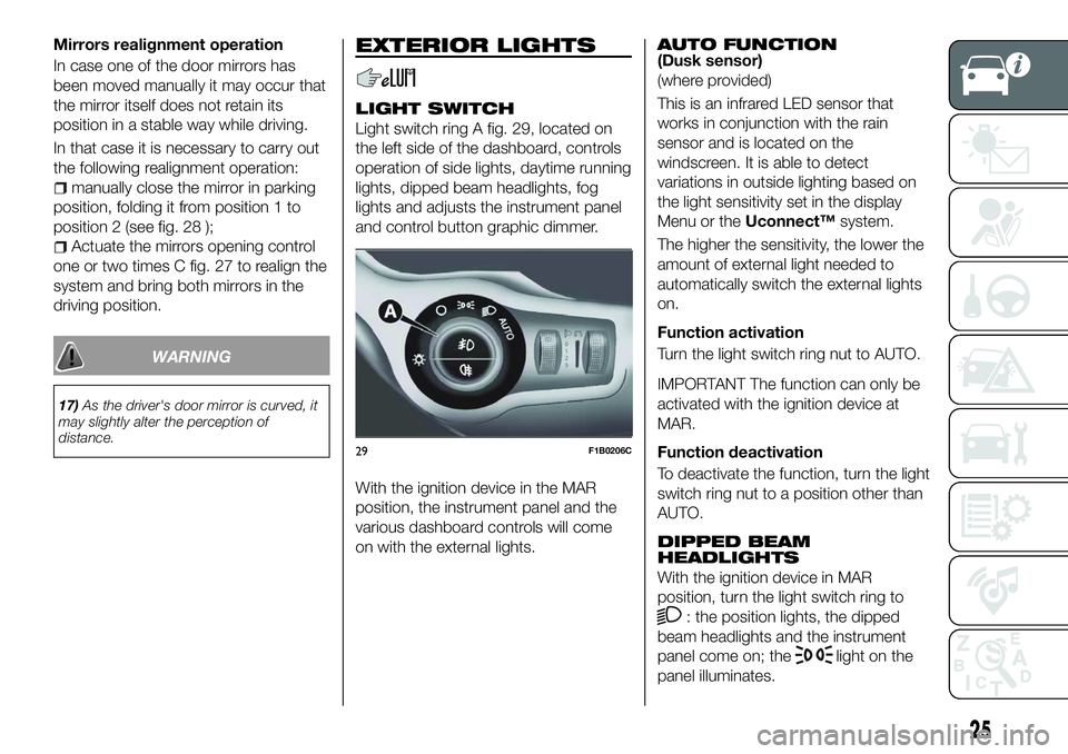
manually close the mirror in parking
position, folding it from position 1 to
position 2 (see fig. 28 );
Actuate the mirrors opening control
one or two times C fig. 27 to realign the
system and bring both mirrors in the
driving position.
WARNING
17) As the driver's door mirror is curved, it
may slightly alter the perception of
distance.
EXTERIOR LIGHTS
LIGHT SWITCH
Light switch ring A fig. 29, located on
the left side of the dashboard, controls
operation of side lights, daytime running
lights, dipped beam headlights, fog
lights and adjusts the instrument panel
and control button graphic dimmer.
With the ignition device in the MAR
position, the instrument panel and the
various dashboard controls will come
on with the external lights.
AUTO FUNCTION(Dusk sensor)
(where provided)
This is an infrared LED sensor that
works in conjunction with the rain
sensor and is located on the
windscreen. It is able to detect
variations in outside lighting based on
the light sensitivity set in the display
Menu or the Uconnect™ system.
The higher the sensitivity, the lower the
amount of external light needed to
automatically switch the external lights
on.
Function activation
Turn the light switch ring nut to AUTO.
IMPORTANT The function can only be
activated with the ignition device at
MAR.
Function deactivation
To deactivate the function, turn the light
switch ring nut to a position other than
AUTO.
DIPPED BEAM
HEADLIGHTS
With the ignition device in MAR
position, turn the light switch ring to
: the position lights, the dipped
beam headlights and the instrument
panel come on; the
light on the
panel illuminates.
29F1B0206C
25
Page 28 of 276
DAYTIME RUNNING
LIGHTS (DRL)
"Daytime Running Lights"
18) 19)
With the ignition device in the MAR
position and the light ring turned to the
Oposition, the daytime running lights
are automatically activated. The other
lights and interior lighting remain off.
The daytime running lights are
temporarily deactivated when the
direction indicators are activated. When
the direction indicators are deactivated,
the daylight running lights are
reactivated.
FOG LIGHTS(where provided)
The fog light switch is integrated with
the light switch.
With the ignition device in the MAR
position and the dipped beam
headlights on, press the
button to
switch on the fog lights.
When the fog lights are on, the position
and number plates lights are on while
the daytime running lights are off.
To switch them off, press the button
again or turn the light switch ring to O.
REAR FOG LIGHT(where provided)
The button which turns the rear fog light
on and off is integrated in the light
switch.
With the ignition device in the MAR
position and the dipped beam
headlights or fog lights on, press the
button to switch on the rear fog
light.
PARKING LIGHTS
These can be turned on by turning the
light switch ring to the
position.
The
warning light switches on in
the instrument panel.
IMPORTANT NOTE Do not select this
light switch position when the car is
moving, but only to indicate that the car
is parked when prescribed by the
regulations in force in the country where
you are driving (Highway Code).
To turn the lights off, turn the light
switch ring to the Oposition
HEADLIGHTS OFF DELAY
(Follow me home)
Activation
With multifunction display and
Uconnect™Radio: turn the ignition
device to STOP. Within 2 minutes, pull
the left stalk to headlight flashing mode:
the headlight off delay is activated for
30 seconds. The function can be activated for 7 times in sequence, i.e.
up to a total of 210 seconds.
With reconfigurable multifunction
display and/orUconnect™7'': the
headlight off delay can be set (from 0,
30, 60 to 90 seconds) in the Menu.
If the headlight off delay is set to
0 seconds, it is possible to turn on the
lights for a predefined time of
30 seconds using the main beam
headlights stalk within 2 minutes after
stopping the engine. It is possible to
turn on the lights 7 times, for a
maximum of 210 seconds.
If the value set on the Menu is different
from 0, the lights can be switched of for
the predetermined time by taking the
ring from position
(with the engine
running) to position O(with the engine
off).
The function can be activated
automatically on versions with dusk
sensor: turn the ring to the AUTO
position with the engine running. The
dipped beam headlights will be turned
on if the sensor detects a low level of
light. The headlights off delay is
activated automatically when the engine
is switched off with the headlights on
for the time selected in the Menu.
26
GETTING TO KNOW YOUR CAR
Page 29 of 276
Deactivation
If the function is activated by using the
left steering wheel stalk, the function
can be deactivated by holding the left
lever in "main beam flashing" mode for
longer than 2 seconds or by waiting for
the deactivation time shown on the
display.
The function cannot be deactivated if it
is activated using the light line. The
headlights will be switched off at the
end of the set time.
Turning the ignition device to the MAR
position will deactivate the function.
MAIN BEAM HEADLIGHTS
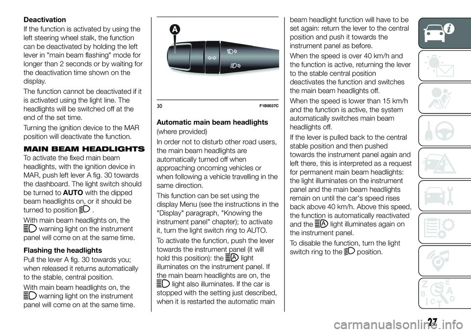
To activate the fixed main beam
headlights, with the ignition device in
MAR, push left lever A fig. 30 towards
the dashboard. The light switch should
be turned toAUTOwith the dipped
beam headlights on, or it should be
turned to position
.
With main beam headlights on, the
warning light on the instrument
panel will come on at the same time.
Flashing the headlights
Pull the lever A fig. 30 towards you;
when released it returns automatically
to the stable, central position.
With main beam headlights on, the
warning light on the instrument
panel will come on at the same time. Automatic main beam headlights
(where provided)
In order not to disturb other road users,
the main beam headlights are
automatically turned off when
approaching oncoming vehicles or
when following a vehicle travelling in the
same direction.
This function can be set using the
display Menu (see the instructions in the
"Display" paragraph, "Knowing the
instrument panel" chapter); to activate
it, turn the light switch ring to AUTO.
To activate the function, push the lever
towards the instrument panel (it will
hold this position): the
light
illuminates on the instrument panel. If
the main beam headlights are on, the
light also illuminates. If the car is
stopped with the setting just described,
when it is restarted the automatic main beam headlight function will have to be
set again: return the lever to the central
position and push it towards the
instrument panel as before.
When the speed is over 40 km/h and
the function is active, returning the lever
to the stable central position
deactivates the function and switches
the main beam headlights off.
When the speed is lower than 15 km/h
and the function is active, the system
automatically switches main beam
headlights off.
If the lever is pulled back to the central
stable position and then pushed
towards the instrument panel again and
left there, this is interpreted as a request
for permanent main beam headlights:
the light illuminates on the instrument
panel and the main beam headlights
remain on until the car's speed rises
back above 40 km/h. Above this speed,
the function is automatically reactivated
and the
light illuminates again on
the instrument panel.
To disable the function, turn the light
switch ring to the
position.
30F1B0037C
27
Page 30 of 276
DIRECTION INDICATORS
Bring left stalk A fig. 30 to the (stable)
position:
upwards: activates the right direction
indicator;
downwards: activates the left direction
indicator.
The
orwarning light respectively
will flash on the instrument panel.
The direction indicators switch off
automatically when the steering wheel
is straightened or when the daytime
running lights (DRL)/parking lights are
activated.
"Lane Change" function
If you wish to signal a lane change while
running, place the left stalk in the
unstable position for less than half a
second.
The direction indicator on the side
selected will flash five times and then
switch off automatically.
HEADLIGHT ALIGNMENT
ADJUSTMENT
Headlight alignment corrector
The headlight alignment corrector
operates with ignition device at MAR
and dipped headlights on.
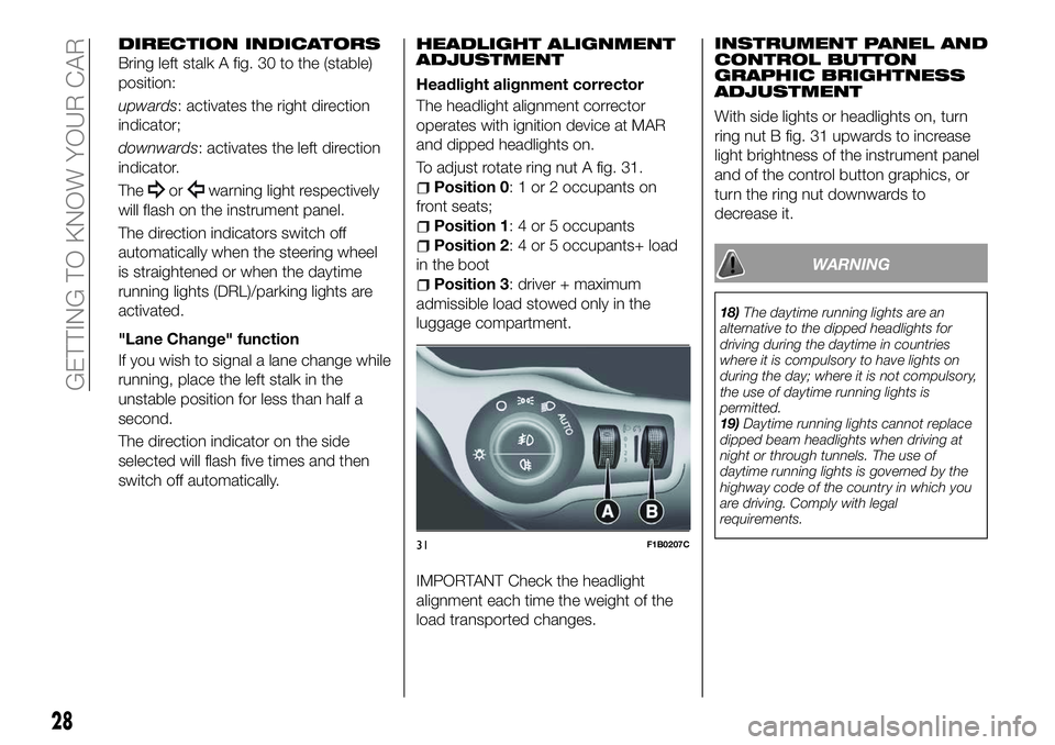
To adjust rotate ring nut A fig. 31.
Position 0: 1 or 2 occupants on
front seats;
Position 1: 4 or 5 occupants
Position 2: 4 or 5 occupants+ load
in the boot
Position 3: driver + maximum
admissible load stowed only in the
luggage compartment.
IMPORTANT Check the headlight
alignment each time the weight of the
load transported changes. INSTRUMENT PANEL AND
CONTROL BUTTON
GRAPHIC BRIGHTNESS
ADJUSTMENT
With side lights or headlights on, turn
ring nut B fig. 31 upwards to increase
light brightness of the instrument panel
and of the control button graphics, or
turn the ring nut downwards to
decrease it.
WARNING
18)
The daytime running lights are an
alternative to the dipped headlights for
driving during the daytime in countries
where it is compulsory to have lights on
during the day; where it is not compulsory,
the use of daytime running lights is
permitted.
19) Daytime running lights cannot replace
dipped beam headlights when driving at
night or through tunnels. The use of
daytime running lights is governed by the
highway code of the country in which you
are driving. Comply with legal
requirements.
31F1B0207C
28
GETTING TO KNOW YOUR CAR
Page 34 of 276
If, after using the function, the ignition
device is set back to MAR with the
blades in a position other than rest
position (at the base of the windscreen),
they will only return to rest position
following a command given using the
stalk (stalk upwards, into unstable
position) or when a speed of 5 km/h is
exceeded.
IMPORTANT Before activating the
function, make sure that when the
engine is turned on the windscreen
wiper is free of snow or ice
Deactivation
The function is deactivated if:
2 minutes have passed since the
ignition device was set to STOP;
the ignition device is set to MAR and
the blades are in rest position;
the ignition device is set to MAR and
a wiping command is carried out.
REAR WINDOW WIPER/
WASHER
Turn the ring B fig. 33 to set the
rearscreen wiper to operate in the
following modes:
continuous: when ring is in the
position;
intermittent: when ring is in the
position and the windscreen wiper is
stationary;
synchronous: when the rearscreen
wiper ring is in the
position and the
windscreen wiper is moving or set to
AUTO. In this mode, the rear window
wiper makes one stroke for each two
strokes of the windscreen wiper;
single wipe: with the selector in the
position, the windscreen wiper on
and reverse gear engaged.
Push the stalk towards the dashboard
(rocking position) to activate the rear
window washer jet. Keep pushing the
lever to automatically activate both the
rear window washer jet and the rear
window wiper with a single movement.
Releasing the stalk will activate three
strokes, as described for the
windscreen wiper. The smart wash
cycle will not be performed if the ring is
in the
position.
Deactivation
The function stops when the stalk is
released.
WARNING
20) If the window needs to be cleaned,
make sure the device is deactivated or the
ignition button and the key are on STOP.
IMPORTANT
7) Never use the windscreen wipers to
remove layers of snow or ice from the
windscreen. In such conditions, the
windscreen wiper may be subjected to
excessive stress and the motor cut-out
switch, which prevents operation for a few
seconds, may intervene. If operation is not
subsequently restored, even after restarting
the engine, contact a Fiat Dealership.
8) Do not operate the windscreen wiper
with the blades lifted from the windscreen.
9) Do not activate the rain sensor when
washing the car in an automatic car wash.
10) Make sure the device is switched off if
there is ice on the windscreen.
32
GETTING TO KNOW YOUR CAR
Page 40 of 276
The window is therefore lowered by
about 5 cm from its initial stop position.
The window cannot be operated in any
way during this time.
Electric window system
initialisation
If power supply is interrupted, the
electric window automatic operation
must be reinitialised.
The initialisation procedure described
below must be carried out with the
doors closed and for each door:
close the window by holding down
the button;
once the window has closed
completely, keep holding the button
down for at least a further 3 seconds.
WARNING
21) Incorrect use of the electric windows
may be dangerous. Before and during
operation, always check that nobody is
exposed to the risk of being injured either
directly by the moving window or through
objects getting caught or hit by it. When
leaving the vehicle (equipped with
mechanical key with remote control),
always remove the key from the ignition
device to prevent accidental operation of
the electric windows from being a hazard
for those still on board.
ELECTRIC SUN
ROOF
22)11)
The electric sun roof comprises two
glass panels (the front one is mobile
and the rear one fixed) and is fitted with
two manually operated sun blinds.
Operation of the sun roof is only
possible with the ignition device at
MAR.
OPENING
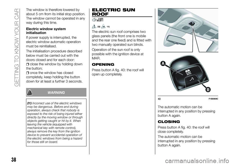
Press button A fig. 40: the roof will
open up completely.
The automatic motion can be
interrupted in any position by pressing
button A again.
CLOSING
Press button A fig. 40: the roof will
close completely.
The automatic motion can be
interrupted in any position by pressing
button A again.
40F1B0069C
38
GETTING TO KNOW YOUR CAR
Page 41 of 276
SWIVEL OPENING
To bring the roof into "swivel" position,
press and release button B fig. 40.
This type of swivel-opening can be
activated irrespective of the position of
the sun roof. When starting with the
roof in closed position, pressing the
button automatically causes its
swivel-opening. If the roof is already
open, the button must be held until the
roof reaches the swivel-opening
position.
Pressing button B again during
automatic movement of the roof will
stop it.
SUN BLIND MOVEMENT
The blind is manually-operated: it can
be stopped in any position.
ANTI-PINCH DEVICE
The sun roof has an anti-pinch safety
system capable of detecting the
presence of an obstacle during the
closing movement: if this happens, the
system intervenes and the movement of
the roof is immediately reversed into
opening.
EMERGENCY OPERATION
If the control buttons fail to operate, the
sun roof can be moved manually,
proceeding as described below:
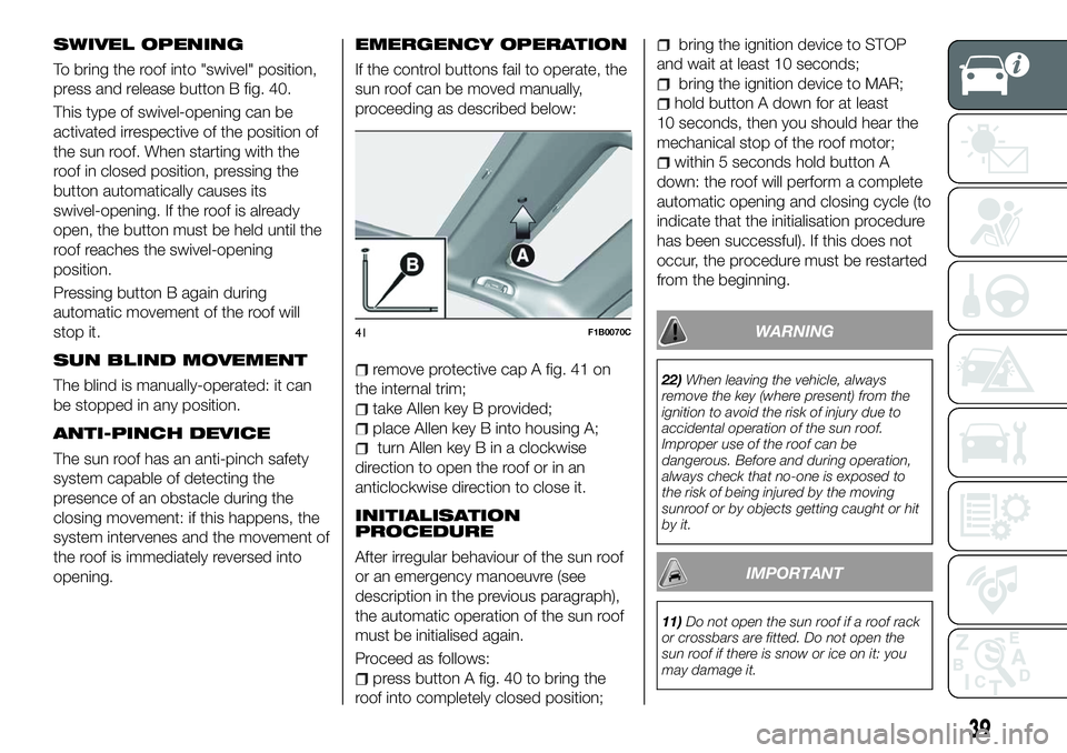
remove protective cap A fig. 41 on
the internal trim;
take Allen key B provided;
place Allen key B into housing A;
turn Allen key B in a clockwise
direction to open the roof or in an
anticlockwise direction to close it.
INITIALISATION
PROCEDURE
After irregular behaviour of the sun roof
or an emergency manoeuvre (see
description in the previous paragraph),
the automatic operation of the sun roof
must be initialised again.
Proceed as follows:
press button A fig. 40 to bring the
roof into completely closed position;
bring the ignition device to STOP
and wait at least 10 seconds;
bring the ignition device to MAR;
hold button A down for at least
10 seconds, then you should hear the
mechanical stop of the roof motor;
within 5 seconds hold button A
down: the roof will perform a complete
automatic opening and closing cycle (to
indicate that the initialisation procedure
has been successful). If this does not
occur, the procedure must be restarted
from the beginning.
WARNING
22) When leaving the vehicle, always
remove the key (where present) from the
ignition to avoid the risk of injury due to
accidental operation of the sun roof.
Improper use of the roof can be
dangerous. Before and during operation,
always check that no-one is exposed to
the risk of being injured by the moving
sunroof or by objects getting caught or hit
by it.
IMPORTANT
11) Do not open the sun roof if a roof rack
or crossbars are fitted. Do not open the
sun roof if there is snow or ice on it: you
may damage it.
41F1B0070C
39
Page 42 of 276
BONNET
OPENING
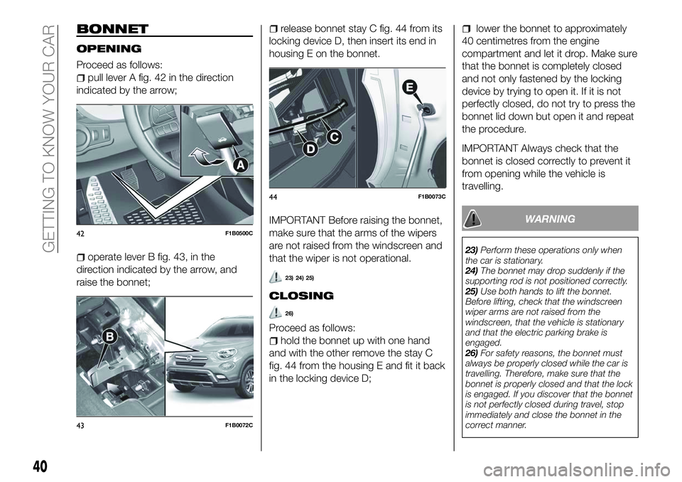
Proceed as follows:
pull lever A fig. 42 in the direction
indicated by the arrow;
operate lever B fig. 43, in the
direction indicated by the arrow, and
raise the bonnet;
release bonnet stay C fig. 44 from its
locking device D, then insert its end in
housing E on the bonnet.
IMPORTANT Before raising the bonnet,
make sure that the arms of the wipers
are not raised from the windscreen and
that the wiper is not operational.
23) 24) 25)
CLOSING
26)
Proceed as follows:
hold the bonnet up with one hand
and with the other remove the stay C
fig. 44 from the housing E and fit it back
in the locking device D;
lower the bonnet to approximately
40 centimetres from the engine
compartment and let it drop. Make sure
that the bonnet is completely closed
and not only fastened by the locking
device by trying to open it. If it is not
perfectly closed, do not try to press the
bonnet lid down but open it and repeat
the procedure.
IMPORTANT Always check that the
bonnet is closed correctly to prevent it
from opening while the vehicle is
travelling.
WARNING
23) Perform these operations only when
the car is stationary.
24) The bonnet may drop suddenly if the
supporting rod is not positioned correctly.
25) Use both hands to lift the bonnet.
Before lifting, check that the windscreen
wiper arms are not raised from the
windscreen, that the vehicle is stationary
and that the electric parking brake is
engaged.
26) For safety reasons, the bonnet must
always be properly closed while the car is
travelling. Therefore, make sure that the
bonnet is properly closed and that the lock
is engaged. If you discover that the bonnet
is not perfectly closed during travel, stop
immediately and close the bonnet in the
correct manner.
42F1B0500C
43F1B0072C
44F1B0073C
40
GETTING TO KNOW YOUR CAR
Page 44 of 276
BOOT INITIALISATION
IMPORTANT If the battery is
disconnected or the protection fuse
blows, the boot opening/closing
mechanism must be reinitialised as
follows:
close all the doors and the boot;
press the"FIAT" button on the
remote control;
press thebutton on the remote
control.
LOAD COMPARTMENT
FEATURES
Reconfigurable load platform
12)
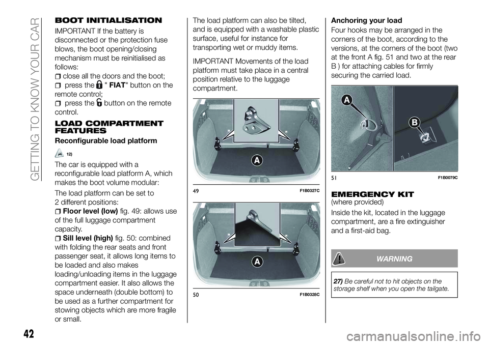
The car is equipped with a
reconfigurable load platform A, which
makes the boot volume modular:
The load platform can be set to
2 different positions:
Floor level (low) fig. 49: allows use
of the full luggage compartment
capacity.
Sill level (high) fig. 50: combined
with folding the rear seats and front
passenger seat, it allows long items to
be loaded and also makes
loading/unloading items in the luggage
compartment easier. It also allows the
space underneath (double bottom) to
be used as a further compartment for
stowing objects which are more fragile
or small. The load platform can also be tilted,
and is equipped with a washable plastic
surface, useful for instance for
transporting wet or muddy items.
IMPORTANT Movements of the load
platform must take place in a central
position relative to the luggage
compartment.
Anchoring your load
Four hooks may be arranged in the
corners of the boot, according to the
versions, at the corners of the boot (two
at the front A fig. 51 and two at the rear
B ) for attaching cables for firmly
securing the carried load.
EMERGENCY KIT(where provided)
Inside the kit, located in the luggage
compartment, are a fire extinguisher
and a first-aid bag.
WARNING
27)
Be careful not to hit objects on the
storage shelf when you open the tailgate.
49F1B0327C
50F1B0328C
51F1B0079C
42
GETTING TO KNOW YOUR CAR