wiring FIAT BARCHETTA 2003 1.G Owners Manual
[x] Cancel search | Manufacturer: FIAT, Model Year: 2003, Model line: BARCHETTA, Model: FIAT BARCHETTA 2003 1.GPages: 170, PDF Size: 3.55 MB
Page 64 of 170

63
CELLULAR PHONE SETUP
(where fitted)
Your vehicle may be equipped with
an optional cellular phone system con-
sisting of:
– a dual function speaker (sound sys-
tem and cellular phone) located under
the dashboard on the right-hand side;– a dual function, electrically-oper-
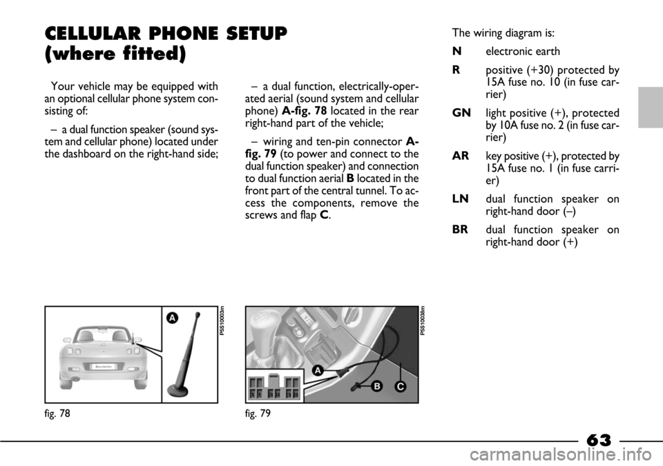
ated aerial (sound system and cellular
phone) A-fig. 78located in the rear
right-hand part of the vehicle;
– wiring and ten-pin connector A-
fig. 79(to power and connect to the
dual function speaker) and connection
to dual function aerial Blocated in the
front part of the central tunnel. To ac-
cess the components, remove the
screws and flap C.The wiring diagram is:
Nelectronic earth
Rpositive (+30) protected by
15A fuse no. 10 (in fuse car-
rier)
GNlight positive (+), protected
by 10A fuse no. 2 (in fuse car-
rier)
ARkey positive (+), protected by
15A fuse no. 1 (in fuse carri-
er)
LNdual function speaker on
right-hand door (–)
BRdual function speaker on
right-hand door (+)
fig. 78
P5S10003m
fig. 79
P5S10038m
Page 126 of 170

125
– Do not connect or disconnect the
terminals of the electronic units while
the ignition key is at MAR.
– Do not check polarity through
sparking.
– Disconnect the electronic units if
you are electrically welding the car
body. Remove the units if tempera-
tures exceed 80°C. (special operations
on the bodywork etc.)
IMPORTANTIf the radio or car
alarm systems are not installed cor-
rectly, they can interfere with the
working of the electronic control
units.ELECTRONIC
CONTROL UNITS
When the car is being used normal-
ly, special measures are not necessary.
The following instructions must be
followed very carefully however, if you
work on the electrical system or in
cases where starting with another bat-
tery is necessary:
– Never disconnect the battery from
the electrical system while the engine
is running.
– When recharging, disconnect the
battery from the wiring system. The
latest battery chargers can, in fact, gen-
erate voltages of up to 20V.
– Never start the engine with a bat-
tery charger. Always use another bat-
tery.
– Be particularly careful when con-
necting the battery to the electrical
system. Ensure the battery posts are
connected up to the right leads (the
polarity is correct) and check that the
connection has been made properly.
Battery Maximum admitted
stand-by intake
50Ah 30 mA
Furthermore, remember that high in-
take electric devices (such as baby bot-
tle warmers, vacuum cleaners, cellular
phones, mini-fridges, etc.) powered
when the engine is off can run the
battery down.
IMPORTANT If you need to install
added systems to the car, improper
wiring connections, in particular if they
affect safety devices, are dangerous.The total intake of these systems
(factory and after-market) must be less
than 0.6 mA x Ah (of the battery) as
shown in the following table:
Modifications or repairs to
the electrical system car-
ried out incorrectly and without
bearing the features of the system
in mind can cause malfunctions
with the risk of fire.
WARNING
Page 151 of 170

150
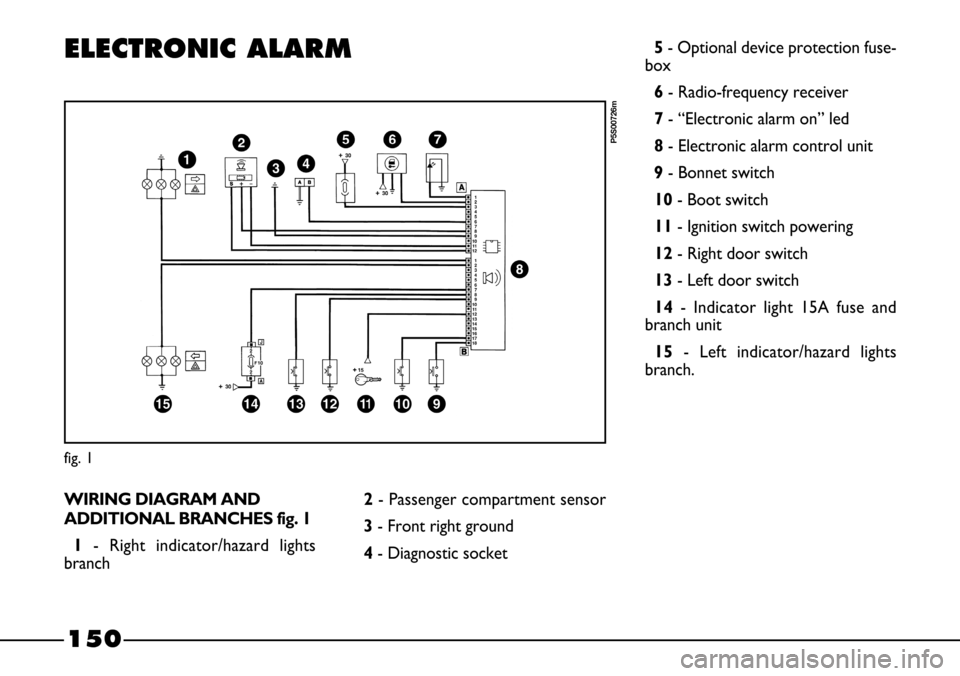
ELECTRONIC ALARM
WIRING DIAGRAM AND
ADDITIONAL BRANCHES fig. 1
1- Right indicator/hazard lights
branch
fig. 1
P5S00726m
2- Passenger compartment sensor
3- Front right ground
4- Diagnostic socket5- Optional device protection fuse-
box
6- Radio-frequency receiver
7- “Electronic alarm on” led
8- Electronic alarm control unit
9- Bonnet switch
10- Boot switch
11- Ignition switch powering
12- Right door switch
13- Left door switch
14- Indicator light 15A fuse and
branch unit
15 - Left indicator/hazard lights
branch.