sensor FIAT BRAVO 2012 2.G Owner's Manual
[x] Cancel search | Manufacturer: FIAT, Model Year: 2012, Model line: BRAVO, Model: FIAT BRAVO 2012 2.GPages: 299, PDF Size: 5.81 MB
Page 132 of 299
❒The performance of the parking assistance
system may also be affected by the position of
the sensors. For example, if the geometry is
altered (as a result of wear of the shock
absorbers, suspension), the tyres are changed,
the vehicle is too heavily laden or specific tuning
is carried out that lowers the vehicle.
❒The detection of obstacles at the top part of the
car may not be guaranteed because the system
detects obstacles that could cause an impact with
the car in the bottom part.
AT THE FILLING STATIONPETROL ENGINES
Use unleaded petrol only, with octane number
(R.O.N.) not lower than 95.
To avoid mistakes, the diameter of the fuel filler is
too small to introduce the nozzle of leaded petrol
pumps.
IMPORTANT An inefficient catalytic converter
leads to harmful exhaust emissions, thus
contributing to air pollution.
IMPORTANT Never use leaded petrol, even in
small amounts or in an emergency, as this would
damage the catalytic converter beyond repair.
MOTORI DIESEL - Operation at low
temperatures
If the outside temperature is very low, diesel
thickens due to the formation of paraffin clots with
consequent defective operation of the fuel supply
system.
In order to avoid these problems, different types of
diesel are distributed according to the season:
summer type, winter type and arctic type
(cold/mountain areas). If refuelling with diesel fuel
whose specifications are not suitable for the
current temperature, it is advisable to mix TUTELA
DIESEL ART additive in the proportions shown on
128GETTING TO
KNOW YOUR CAR
SAFETY
STARTING AND
DRIVING
WARNING LIGHTS
AND MESSAGES
IN AN EMERGENCY
SERVICING AND
MAINTENANCE
TECHNICAL
SPECIFICATIONS
INDEX
Page 134 of 299
WARNING
Do not bring naked flames or lit
cigarettes near to the fuel tank
opening: fire risk. Keep your face away from
the fuel filler to prevent breathing in harmful
vapours.
PROTECTING THE ENVIRONMENTThe following devices are used for reducing petrol
fuel engine emissions:
❒three-way catalytic converter (catalytic
converter)
❒oxygen sensors
❒evaporation control system.
In addition, do not let the engine run, even for a
test, with one or more spark plugs disconnected.
The following devices are used for reducing diesel
fuel engine emissions:
❒oxidising catalytic converter
❒exhaust gas recirculation system (EGR)
❒particulate filter (DPF).
WARNING
The catalytic converter develops high
temperature during operation. Do
not park the car on grass, dry leaves, pine
needles or other flammable material: fire
hazard.
130GETTING TO
KNOW YOUR CAR
SAFETY
STARTING AND
DRIVING
WARNING LIGHTS
AND MESSAGES
IN AN EMERGENCY
SERVICING AND
MAINTENANCE
TECHNICAL
SPECIFICATIONS
INDEX
Page 176 of 299
GENERIC FAILURE INDICATION
(amber)
Fuel cut-off inertia switch tripped
This warning light (or symbol on the display) comes
on when the fuel cut-off inertia switch is triggered.
The display shows the dedicated message.
Engine oil pressure sensor failure
This warning light (or symbol on the display)
switches on when a failure is detected in the engine
oil pressure sensor.
Start&Stop failure
(for versions/markets, where provided)
(versions with multifunction display)
The warning light comes on when a failure is
detected in the Start&Stop system. The display
shows the dedicated message.
Dusk sensor failure
This warning light (or symbol on the display)
switches on when a failure is detected in the dusk
sensor. The display shows the dedicated message.Preset speed limit exceeded (for Arab
countries only)
This warning light (amber), or symbol on the display
(red), switches on when the preset speed limit of
120 km/h is exceeded.
Rain sensor failure
This warning light (or symbol on the display)
switches on when a failure is detected in the rain
sensor. The display shows the dedicated message.
Parking sensor failure
(for versions/markets, where provided)
The warning light (or symbol on the display)
switches on when a parking sensor failure
is detected.
Tyre pressure monitoring system failure
(for versions/markets, where provided)
This warning light (or symbol on the display)
switches on when a TPMS failure is detected.
Should one or more wheels without a sensor be
fitted, the instrument panel warning light will come
on and stay on until the initial conditions are
restored. The display shows the dedicated message.
NoteIf one of the above mentioned failures
occurs, contact a Fiat Dealership as soon as
possible.
172GETTING TO KNOW
YOUR CAR
SAFETY
STARTING AND
DRIVINGWARNING LIGHTS
AND MESSAGESIN AN EMERGENCY
SERVICING AND
MAINTENANCE
TECHNICAL
SPECIFICATIONS
INDEX
Page 181 of 299
TPMS FAILURE
(for versions/markets, where provided)
On some versions, the display shows a message and
an amber symbol when a tyre pressure monitoring
system (TPMS) fault is detected: in this case,
contact a Fiat Dealership as soon as possible.
Should one or more wheels be fitted without
sensors, the display will show a warning message
until initial conditions are restored.INSUFFICIENT TYRE PRESSURE
(amber-red) / CHECK TYRE
PRESSURE (amber) / TYRE
PRESSURE UNSUITABLE FOR
SPEED (amber)
(for versions/markets, where provided)
This warning light switches on when the ignition
key is turned to MAR-ON, but it should switch off
after a few seconds.
Insufficient tyre pressure
The warning light (amber), or symbol in the display
(red), switch on when the inflation pressure of
one or more tyres falls below a preset level. In this
way the TPMS warns the driver that one or more
tyres may be dangerously flat and liable to
puncture.IMPORTANT Do not continue driving with one or
more flat tyres as handling may be compromised.
Stop the car, avoiding harsh braking and steering
manoeuvres. Replace the wheel immediately with
the space-saver wheel (for versions/markets, where
provided) or carry out a repair using the dedicated
kit (see “Changing a wheel” in the "In an
emergency" chapter) and contact a Fiat Dealership
as soon as possible.
Check tyre pressure
This warning light (or symbol in the display)
switches on in the instrument panel to indicate that
the tyre pressure is below the value recommended
to guarantee long tyre life and low fuel
consumption. It may also indicate a slow loss of
pressure.
Should two or more tyres be flat, the display will
show the indications corresponding to each tyre in
sequence.
Restore correct tyre pressures as soon as possible
(see “Cold tyre pressures” in the “Technical data”
chapter).
Tyre pressure unsuitable for speed
Should you need to travel at a speed higher than
160 km/h, inflate the tyres to the pressures
specified in “Tyre pressures” paragraph.
If the TPMS system (for versions/markets where
provided) detects that the pressure of one or more
tyres is unsuitable for the current speed, the
177GETTING TO KNOW
YOUR CAR
SAFETY
STARTING AND
DRIVINGWARNING LIGHTS
AND MESSAGESIN AN EMERGENCY
SERVICING AND
MAINTENANCE
TECHNICAL
SPECIFICATIONS
INDEX
Page 218 of 299
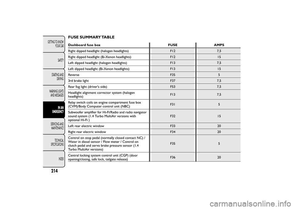
FUSE SUMMARY TABLEDashboard fuse box FUSE AMPS
Right dipped headlight (halogen headlights) F12 7,5
Right dipped headlight (Bi-Xenon headlights) F12 15
Left dipped headlight (halogen headlights) F13 7,5
Left dipped headlight (Bi-Xenon headlights) F13 15
Reverse F35 5
3rd brake light F37 7,5
Rear fog light (driver's side) F53 7,5
Headlight alignment corrector system (halogen
headlights)F13 7,5
Relay switch coils on engine compartment fuse box
(CVM)/Body Computer control unit (NBC)F31 5
Subwoofer amplifier for Hi-Fi/Radio and radio navigator
sound system (1.4 Turbo MultiAir versions with
optional Hi-Fi )F32 15
Left rear electric window F33 20
Right rear electric window F34 20
Control on stop pedal (normally closed contact NC) /
Water in diesel sensor / Flow meter / Control on
clutch pedal and servo brake pressure sensor (1.4
Turbo MultiAir versions)F35 5
Central locking system control unit (CGP) (door
opening/closing, safe lock, tailgate release)F36 20
214GETTING TO KNOW
YOUR CAR
SAFETY
STARTING AND
DRIVING
WARNING LIGHTS
AND MESSAGES
IN AN
EMERGENCY
SERVICING AND
MAINTENANCE
TECHNICAL
SPECIFICATIONS
INDEX
Page 219 of 299
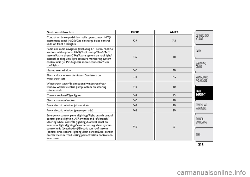
Dashboard fuse box FUSE AMPS
Control on brake pedal (normally open contact NO)/
Instrument panel (NQS)/Gas discharge bulbs control
units on front headlightsF37 7,5
Radio and radio navigator (excluding 1.4 Turbo MultiAir
versions with optional Hi-Fi)/Radio setup/Blue&Me™
system/Alarm siren (CSA)/Alarm system on roof light/
Internal cooling unit/Tyre pressure monitoring system
control unit (CPP)/Diagnosis socket connector/Rear
roof lightsF39 10
Heated rear window F40 30
Electric door mirror demisters/Demisters on
windscreen jetsF41 7,5
Windscreen wiper/Bi-directional windscreen/rear
window washer electric pump system on steering
column stalkF43 30
Current sockets/Cigar lighter F44 15
Electric sun roof motor F46 20
Front electric window (driver side) F47 20
Front electric window (passenger side) F48 20
Emergency control panel (lighting)/Right branch central
control panel (lighting, ASR switch) and left branch/
Steering wheel controls (lighting)/Control panel on
front roof light (lighting)/Volume sensing alarm system
control unit (deactivation)/Electric sun roof system
(control unit, control lighting)/Rain sensor/Dusk sensor
on rear view mirror/Heating pad activation controls on
front seatsF49 5
215GETTING TO KNOW
YOUR CAR
SAFETY
STARTING AND
DRIVING
WARNING LIGHTS
AND MESSAGESIN AN
EMERGENCYSERVICING AND
MAINTENANCE
TECHNICAL
SPECIFICATIONS
INDEX
Page 220 of 299
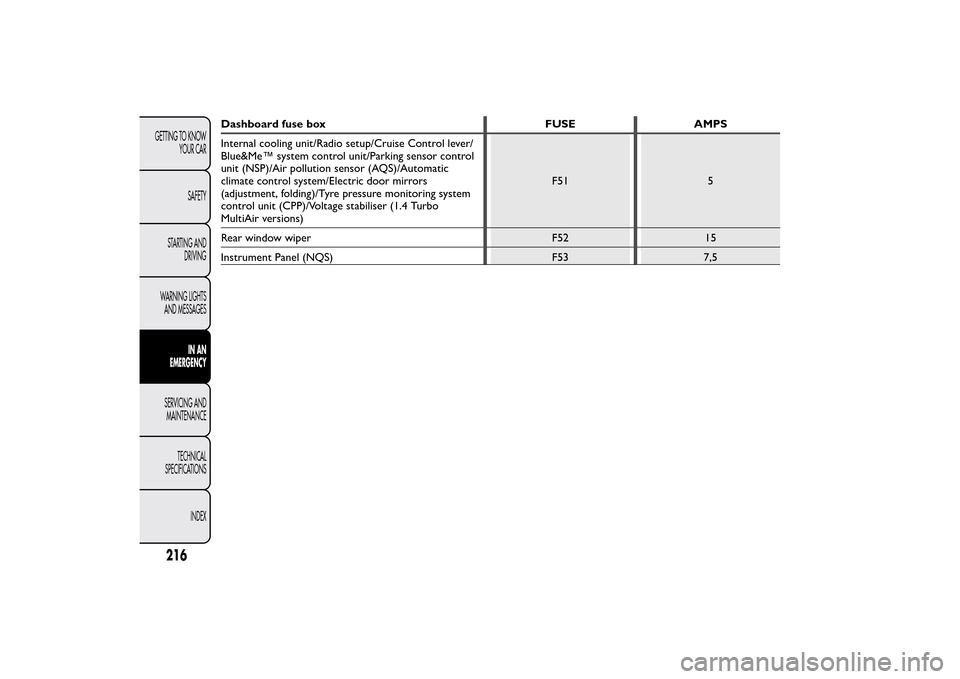
Dashboard fuse box FUSE AMPS
Internal cooling unit/Radio setup/Cruise Control lever/
Blue&Me™ system control unit/Parking sensor control
unit (NSP)/Air pollution sensor (AQS)/Automatic
climate control system/Electric door mirrors
(adjustment, folding)/Tyre pressure monitoring system
control unit (CPP)/Voltage stabiliser (1.4 Turbo
MultiAir versions)F51 5
Rear window wiper F52 15
Instrument Panel (NQS) F53 7,5
216GETTING TO KNOW
YOUR CAR
SAFETY
STARTING AND
DRIVING
WARNING LIGHTS
AND MESSAGES
IN AN
EMERGENCY
SERVICING AND
MAINTENANCE
TECHNICAL
SPECIFICATIONS
INDEX
Page 221 of 299
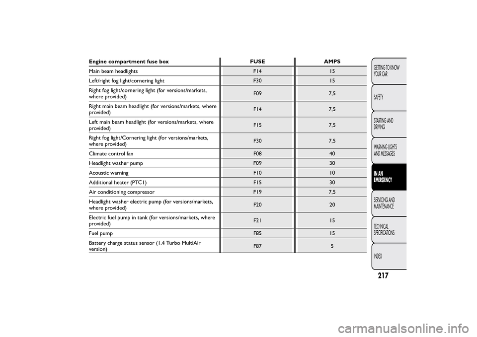
Engine compartment fuse box FUSE AMPS
Main beam headlights F14 15
Left/right fog light/cornering light F30 15
Right fog light/cornering light (for versions/markets,
where provided)F09 7,5
Right main beam headlight (for versions/markets, where
provided)F14 7,5
Left main beam headlight (for versions/markets, where
provided)F15 7,5
Right fog light/Cornering light (for versions/markets,
where provided)F30 7,5
Climate control fan F08 40
Headlight washer pump F09 30
Acoustic warning F10 10
Additional heater (PTC1) F15 30
Air conditioning compressor F19 7,5
Headlight washer electric pump (for versions/markets,
where provided)F20 20
Electric fuel pump in tank (for versions/markets, where
provided)F21 15
Fuel pump F85 15
Battery charge status sensor (1.4 Turbo MultiAir
version)F87 5
217GETTING TO KNOW
YOUR CAR
SAFETY
STARTING AND
DRIVING
WARNING LIGHTS
AND MESSAGESIN AN
EMERGENCYSERVICING AND
MAINTENANCE
TECHNICAL
SPECIFICATIONS
INDEX
Page 223 of 299
BATTERY RECHARGINGIMPORTANT The battery recharging procedure is
given as information only. You are advised to
contact a Fiat Dealership to have this operation
performed.
Low amperage slow recharging for approximately
24 hours is advised. Charging for a longer time may
damage the battery.
VERSIONS WITHOUT Start&Stop SYSTEM
(for versions/markets, where provided)
Charge the battery as follows:
❒disconnect the negative battery terminal;
❒connect the charger cables to the battery
terminals, observing the polarity;
❒turn on the charger;
❒when it is recharged, turn the charger off before
disconnecting it from the battery;
❒reconnect the negative battery terminal.
VERSIONS WITH Start&Stop SYSTEM
(for versions/markets, where provided)
Charge the battery as follows:
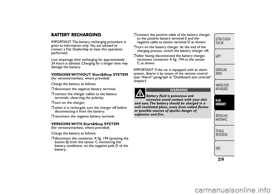
❒disconnect the connector A fig. 194 (pressing the
button B) from the sensor C monitoring the
battery conditions, on the negative pole D of the
battery;❒connect the positive cable of the battery charger
to the positive battery terminal E and the
negative cable to sensor terminal D as shown;
❒turn on the battery charger. At the end of the
charging process, switch the battery charger off;
❒after having disconnected the battery charger,
reconnect connector A fig. 194 to the sensor
C as shown.
IMPORTANT If the car is equipped with an alarm
system, disarm it by means of the remote control
(see "Alarm" paragraph in "Dashboard and controls"
chapter)
WARNING
Battery fluid is poisonous and
corrosive: avoid contact with your skin
and eyes.The battery should be charged in a
well ventilated place, away from naked flames
or possible sources of sparks: danger of
explosion and fire.
219GETTING TO KNOW
YOUR CAR
SAFETY
STARTING AND
DRIVING
WARNING LIGHTS
AND MESSAGESIN AN
EMERGENCYSERVICING AND
MAINTENANCE
TECHNICAL
SPECIFICATIONS
INDEX
Page 293 of 299
INDEX
A
BS (system) .............................. 106
Activation/Deactivation
(CITY function) ......................... 119
Activation of internal air
recirculation and
enablement of AQS
function (Air Quality
System)......................................... 68
Additional heater .............. 59-64-70
Adjustable side vents and
diffusers........................................ 54
Adjusting headlights
alignment .................................... 105
Air cleaner .................................... 240
Air distribution selection ........... 69
Alarm .............................................. 17
Anti-pinch safety device ............. 91
Ashtray ........................................... 88
ASR (system) ............................... 110
Automatic dual zone climate
control system ........................... 65
Automatic headlight sensor
(dusk sensor) .............................. 73
Automatic operation of the
climate control system
(AUTO function) ....................... 66
Battery ......................................... 241
Battery (recharging) ................... 219
Bodywork
– bodywork codes .................... 254
– maintenance ........................... 247
– protection against
atmospheric agents ............... 247
– warranty .................................. 247
Bodywork versions ..................... 254
Bonnet ........................................... 102
Brake Assist.................................. 108
Brake fluid..................................... 239
Brakes
– specifications .......................... 258
bulb replacement ................ 200-202
Bulb replacement
– exterior lights......................... 197
– interior lights .......................... 204
Bulbs
– bulbs (replacement) .............. 193
– general instructions .............. 193
– types of bulbs ......................... 195Car dimensions........................... 269
Cargo box..................................... 102
Carrying children safely ............. 138– child seats................................ 145
– "Universal Isofix" child
seat assembly setup .............. 144
Central diffusers .......................... 55
Central locking ............................. 92
Changing a wheel ........................ 182
Checking fluid levels ................... 230
Child lock device ......................... 93
Cigar lighter .................................. 87
Cleaning and maintenance
– bodywork ................................ 247
– car interior.............................. 250
– engine compartment ............ 249
– front headlights ...................... 249
– Plastic and coated parts....... 251
– seats ......................................... 250
– windows .................................. 249
Climate control/heating
system .......................................... 53
Climate control system
compressor
activation/deactivation.............. 69
Clutch ............................................ 258
CO2 emissions ............................ 279
Code card...................................... 9
289GETTING TO KNOW
YOUR CAR
SAFETY
STARTING AND
DRIVING
WARNING LIGHTS
AND MESSAGES
IN AN EMERGENCY
SERVICING AND
MAINTENANCE
TECHNICAL
SPECIFICATIONSINDEX