FIAT CROMA 2006 2.G Owners Manual
Manufacturer: FIAT, Model Year: 2006, Model line: CROMA, Model: FIAT CROMA 2006 2.GPages: 240, PDF Size: 7.41 MB
Page 151 of 240
151
WARNING
LIGHTS AND
MESSAGES
CAR
MAINTENANCE
TECHNICAL
SPECIFICATIONS
INDEX
DASHBOARD
AND CONTROLS
SAFETY
DEVICES
CORRECT USE
OF THE CAR
IN AN
EMERGENCY
IF A TYRE IS
PUNCTURED
GENERAL INSTRUCTIONS
Wheel changing and correct use of the
jack and space-saver spare wheel call for
some precautions as listed below.
BUMP STARTING
Never bump start the engine (by pushing,
towing, or coasting downhill) as this could
cause fuel to flow into the catalytic exhau-
st system and damage it beyond repair.
Remember that the brake booster and the
power steering system are not operating
until the engine is started, a greater effort
will therefore be required to press the
brake pedal or to turn the steering wheel.
Alert other drivers that the
car is stationary in com-
pliance with local regulations: hazard
warning lights, warning triangle etc.
Any passengers on board should lea-
ve the car, especially if it is heavily la-
den. Passengers should stay away
from oncoming traffic while the
wheel is being changed on. If the
wheel is being changed on a steep or
badly surfaced road, place the wed-
ges or other suitable material under
the wheel to stop the car.
WARNING
The space-saver spare wheel
is specific to your car, do not
use it on other models, or use the spa-
re wheel of other models on your car.
The space-saver spare wheel shall
only be used in an emergency.
It shall only be used for the distance
necessary to reach a service point and
the car speed shall not exceed 80
Km/h. The spare wheel has an oran-
ge sticker that summarises the main
cautions for use and limitations. The
sticker should never be removed or
covered.
Never fit a wheel cap on a space-sa-
ver spare wheel. The sticker gives the
following information in four langua-
ges: caution! For temporary use only!
80 km/h max! Replace by normal
wheel as soon as possible. Do not co-
ver this label.
WARNING
Page 152 of 240

152
WARNING
LIGHTS AND
MESSAGES
CAR
MAINTENANCE
TECHNICAL
SPECIFICATIONS
INDEX
DASHBOARD
AND CONTROLS
SAFETY
DEVICES
CORRECT USE
OF THE CAR
IN AN
EMERGENCY
When driving with a space-
saver spare wheel fitted, the
driving performance of the car chan-
ges. Avoid accelerating or braking
sharply, abrupt turns or fast corne-
rings. The life of the spare wheel is
approx. 3000 Km, after this distance
it should be replaced with another of
the same type. Never attempt to fit
a conventional tyre on a rim designed
for use as a space-saver spare wheel.
Have the punctured wheel repaired
and refitted as soon as possible. Two
or more space-saver spare wheels
should never be used together. Do not
grease the threads of bolts before in-
stalling them: they might slip out.
WARNING
The jack shall only be used
for changing wheels on the
car with which it is provided or on
cars of the same model.
It must not be used for other purpo-
ses such as for instance raising cars of
other models. In no case should it be
used for repairs under the car. Incor-
rect positioning of the jack may cau-
se the jacked car to fall. Do not use
the jack for higher capacities than
stated on its label. Snow chains can-
not be fitted to the space-saver spa-
re wheel. So, if a front (drive) wheel
is punctured and chains are needed,
a rear wheel should be fitted to the
front of the car and the spare wheel
should be fitted to the rear. This way
with two normal drive wheels, snow
chains can be fitted to them to solve
an emergency.
WARNING
Fasten the wheel cap cor-
rectly to prevent the wheel
from coming free in motion. Never
tamper with the inflation valve. Ne-
ver place tools between the rim and
tyre. Check and restore, if required,
the pressure of tyres and spare wheel
to the values given in section “Tech-
nical Specifications”.
WARNING
Page 153 of 240
153
WARNING
LIGHTS AND
MESSAGES
CAR
MAINTENANCE
TECHNICAL
SPECIFICATIONS
INDEX
DASHBOARD
AND CONTROLS
SAFETY
DEVICES
CORRECT USE
OF THE CAR
IN AN
EMERGENCY
To change a wheel proceed as follows:
❒Stop the car in a position that is not
dangerous for oncoming traffic where
you can change the wheel safely. The
ground should be flat and adequately
firm;
❒Turn the engine off and pull up the
handbrake;
❒Engage first gear or reverse (position
P with automatic transmission);
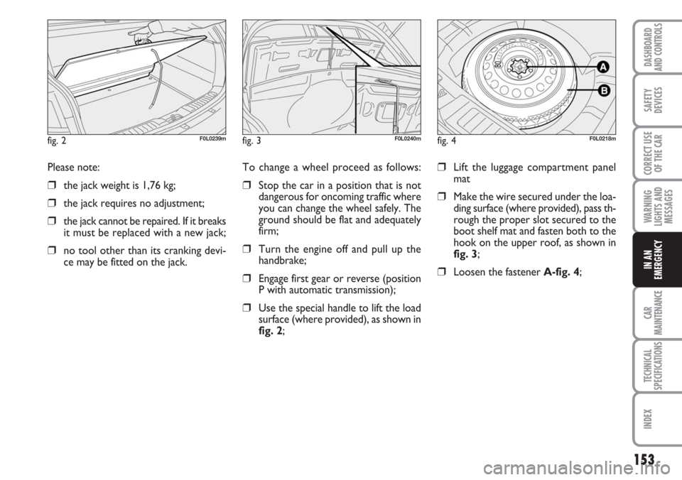
❒Use the special handle to lift the load
surface (where provided), as shown in
fig. 2;
❒Lift the luggage compartment panel
mat
❒Make the wire secured under the loa-
ding surface (where provided), pass th-
rough the proper slot secured to the
boot shelf mat and fasten both to the
hook on the upper roof, as shown in
fig. 3;
❒Loosen the fastener A-fig. 4; Please note:
❒the jack weight is 1,76 kg;
❒the jack requires no adjustment;
❒the jack cannot be repaired. If it breaks
it must be replaced with a new jack;
❒no tool other than its cranking devi-
ce may be fitted on the jack.
fig. 2F0L0239mfig. 3F0L0240mfig. 4F0L0218m
Page 154 of 240
154
WARNING
LIGHTS AND
MESSAGES
CAR
MAINTENANCE
TECHNICAL
SPECIFICATIONS
INDEX
DASHBOARD
AND CONTROLS
SAFETY
DEVICES
CORRECT USE
OF THE CAR
IN AN
EMERGENCY
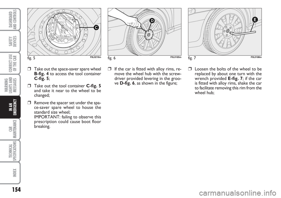
❒If the car is fitted with alloy rims, re-
move the wheel hub with the screw-
driver provided levering in the groo-
ve D-fig. 6, as shown in the figure;❒Loosen the bolts of the wheel to be
replaced by about one turn with the
wrench provided E-fig. 7; if the car
is fitted with alloy rims, shake the car
to facilitate removing this rim from the
wheel hub;❒Take out the space-saver spare wheel
B-fig. 4to access the tool container
C-fig. 5;
❒Take out the tool container C-fig. 5
and take it near to the wheel to be
changed;
❒Remove the spacer set under the spa-
ce-saver spare wheel to house the
standard size wheel;
IMPORTANT: failing to observe this
prescription could cause boot floor
breaking.
fig. 5F0L0219mfig. 6F0L0185mfig. 7F0L0186m
Page 155 of 240
155
WARNING
LIGHTS AND
MESSAGES
CAR
MAINTENANCE
TECHNICAL
SPECIFICATIONS
INDEX
DASHBOARD
AND CONTROLS
SAFETY
DEVICES
CORRECT USE
OF THE CAR
IN AN
EMERGENCY
❒Make sure the contact surfaces
between spare wheel and hub are
clean so that the fastening bolts will
not come loose;
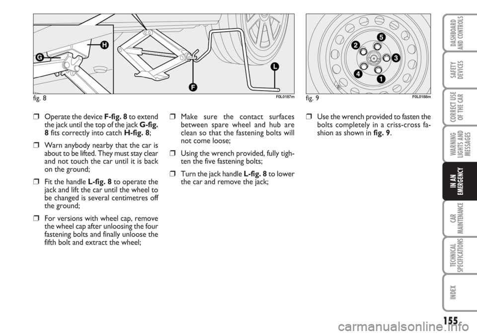
❒Using the wrench provided, fully tigh-
ten the five fastening bolts;
❒Turn the jack handle L-fig. 8to lower
the car and remove the jack;
❒Use the wrench provided to fasten the
bolts completely in a criss-cross fa-
shion as shown in fig. 9.❒Operate the device F-fig. 8to extend
the jack until the top of the jack G-fig.
8fits correctly into catch H-fig. 8;
❒Warn anybody nearby that the car is
about to be lifted. They must stay clear
and not touch the car until it is back
on the ground;
❒Fit the handle L-fig. 8to operate the
jack and lift the car until the wheel to
be changed is several centimetres off
the ground;
❒For versions with wheel cap, remove
the wheel cap after unloosing the four
fastening bolts and finally unloose the
fifth bolt and extract the wheel;
fig. 8F0L0187mfig. 9F0L0188m
Page 156 of 240
156
WARNING
LIGHTS AND
MESSAGES
CAR
MAINTENANCE
TECHNICAL
SPECIFICATIONS
INDEX
DASHBOARD
AND CONTROLS
SAFETY
DEVICES
CORRECT USE
OF THE CAR
IN AN
EMERGENCY
For versions with alloy rims
❒Insert the wheel on the hub and, using
the wrench provided, tighten the
bolts;
❒Lower the car and remove the jack;
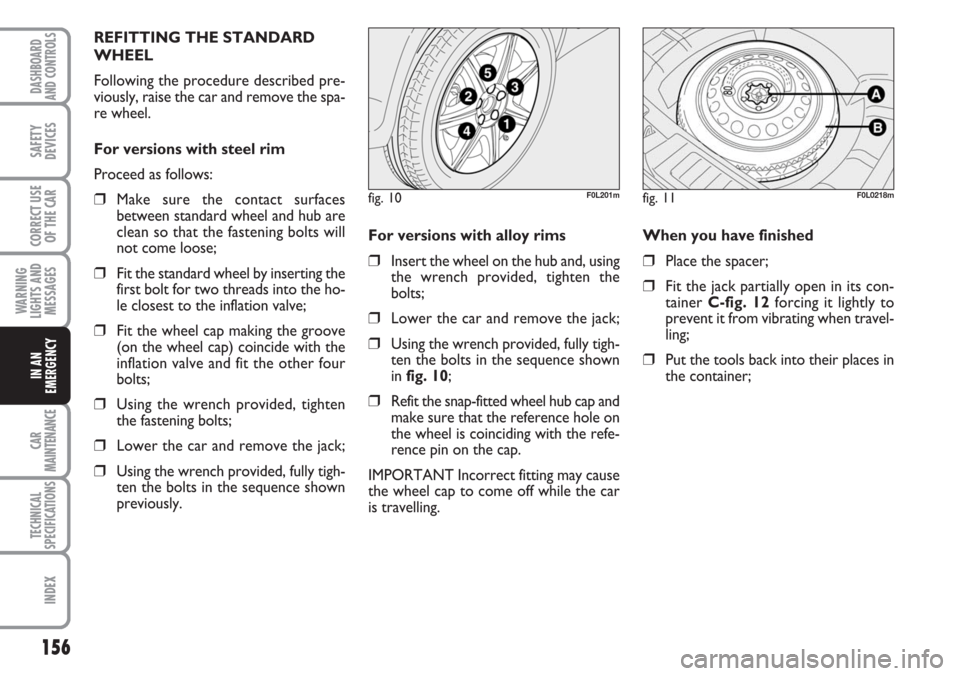
❒Using the wrench provided, fully tigh-
ten the bolts in the sequence shown
in fig. 10;
❒Refit the snap-fitted wheel hub cap and
make sure that the reference hole on
the wheel is coinciding with the refe-
rence pin on the cap.
IMPORTANT Incorrect fitting may cause
the wheel cap to come off while the car
is travelling.When you have finished
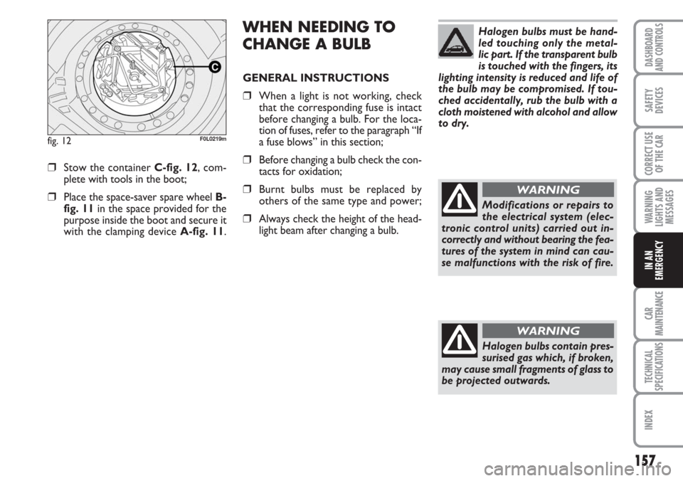
❒Place the spacer;
❒Fit the jack partially open in its con-
tainer C-fig. 12forcing it lightly to
prevent it from vibrating when travel-
ling;
❒Put the tools back into their places in
the container; REFITTING THE STANDARD
WHEEL
Following the procedure described pre-
viously, raise the car and remove the spa-
re wheel.
For versions with steel rim
Proceed as follows:
❒Make sure the contact surfaces
between standard wheel and hub are
clean so that the fastening bolts will
not come loose;
❒Fit the standard wheel by inserting the
first bolt for two threads into the ho-
le closest to the inflation valve;
❒Fit the wheel cap making the groove
(on the wheel cap) coincide with the
inflation valve and fit the other four
bolts;
❒Using the wrench provided, tighten
the fastening bolts;
❒Lower the car and remove the jack;
❒Using the wrench provided, fully tigh-
ten the bolts in the sequence shown
previously.
fig. 10F0L201mfig. 11F0L0218m
Page 157 of 240
157
WARNING
LIGHTS AND
MESSAGES
CAR
MAINTENANCE
TECHNICAL
SPECIFICATIONS
INDEX
DASHBOARD
AND CONTROLS
SAFETY
DEVICES
CORRECT USE
OF THE CAR
IN AN
EMERGENCY
WHEN NEEDING TO
CHANGE A BULB
GENERAL INSTRUCTIONS
❒When a light is not working, check
that the corresponding fuse is intact
before changing a bulb. For the loca-
tion of fuses, refer to the paragraph “If
a fuse blows” in this section;
❒Before changing a bulb check the con-
tacts for oxidation;
❒Burnt bulbs must be replaced by
others of the same type and power;
❒Always check the height of the head-
light beam after changing a bulb.
❒Stow the container C-fig. 12, com-
plete with tools in the boot;
❒Place the space-saver spare wheel B-
fig. 11in the space provided for the
purpose inside the boot and secure it
with the clamping device A-fig. 11.
fig. 12F0L0219m
Halogen bulbs must be hand-
led touching only the metal-
lic part. If the transparent bulb
is touched with the fingers, its
lighting intensity is reduced and life of
the bulb may be compromised. If tou-
ched accidentally, rub the bulb with a
cloth moistened with alcohol and allow
to dry.
Modifications or repairs to
the electrical system (elec-
tronic control units) carried out in-
correctly and without bearing the fea-
tures of the system in mind can cau-
se malfunctions with the risk of fire.
WARNING
Halogen bulbs contain pres-
surised gas which, if broken,
may cause small fragments of glass to
be projected outwards.
WARNING
Page 158 of 240
158
WARNING
LIGHTS AND
MESSAGES
CAR
MAINTENANCE
TECHNICAL
SPECIFICATIONS
INDEX
DASHBOARD
AND CONTROLS
SAFETY
DEVICES
CORRECT USE
OF THE CAR
IN AN
EMERGENCY
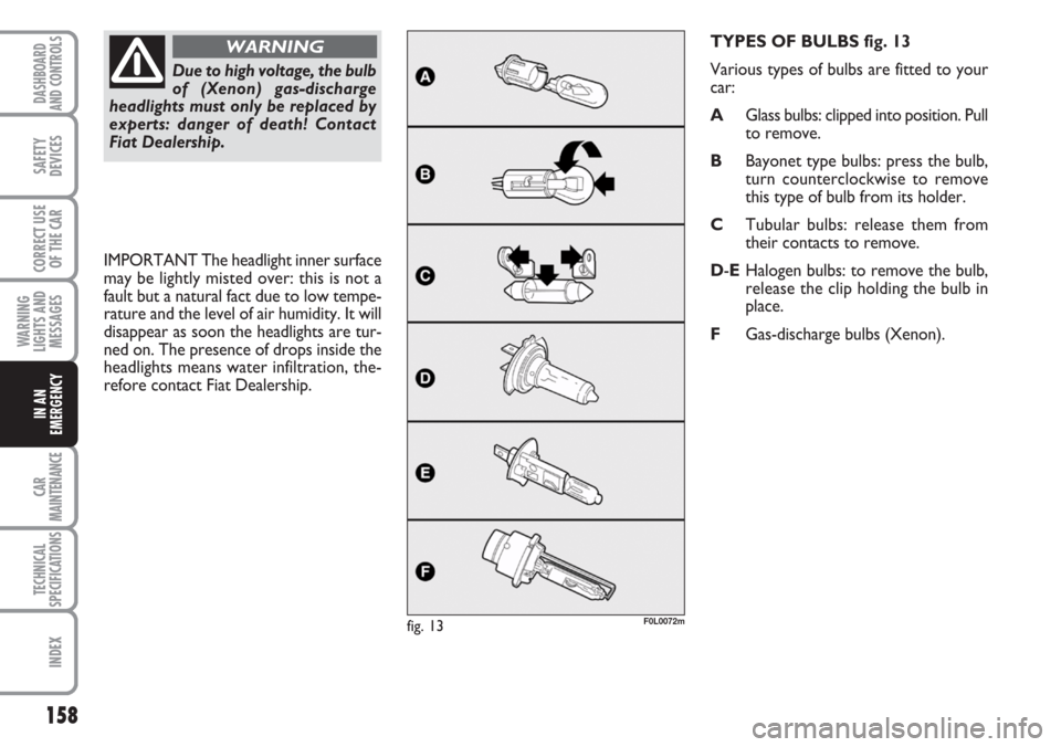
TYPES OF BULBS fig. 13
Various types of bulbs are fitted to your
car:
AGlass bulbs: clipped into position. Pull
to remove.
BBayonet type bulbs: press the bulb,
turn counterclockwise to remove
this type of bulb from its holder.
CTubular bulbs: release them from
their contacts to remove.
D-EHalogen bulbs: to remove the bulb,
release the clip holding the bulb in
place.
FGas-discharge bulbs (Xenon).
F0L0072mfig. 13
Due to high voltage, the bulb
of (Xenon) gas-discharge
headlights must only be replaced by
experts: danger of death! Contact
Fiat Dealership.
WARNING
IMPORTANT The headlight inner surface
may be lightly misted over: this is not a
fault but a natural fact due to low tempe-
rature and the level of air humidity. It will
disappear as soon the headlights are tur-
ned on. The presence of drops inside the
headlights means water infiltration, the-
refore contact Fiat Dealership.
Page 159 of 240
159
WARNING
LIGHTS AND
MESSAGES
CAR
MAINTENANCE
TECHNICAL
SPECIFICATIONS
INDEX
DASHBOARD
AND CONTROLS
SAFETY
DEVICES
CORRECT USE
OF THE CAR
IN AN
EMERGENCY
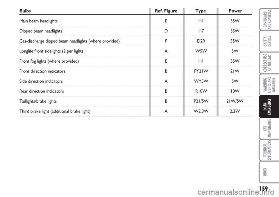
Bulbs Ref. Figure Type Power
Main beam headlights E H1 55W
Dipped beam headlights D H7 55W
Gas-discharge dipped beam headlights (where provided) F D2R 35W
Longlife front sidelights (2 per light) A W5W 5W
Front fog lights (where provided) E H1 55W
Front direction indicators B PY21W 21W
Side direction indicators A WY5W 5W
Rear direction indicators B R10W 10W
Taillights/brake lights B P21/5W 21W/5W
Third brake light (additional brake light) A W2,3W 2,3W
Page 160 of 240
160
WARNING
LIGHTS AND
MESSAGES
CAR
MAINTENANCE
TECHNICAL
SPECIFICATIONS
INDEX
DASHBOARD
AND CONTROLS
SAFETY
DEVICES
CORRECT USE
OF THE CAR
IN AN
EMERGENCY
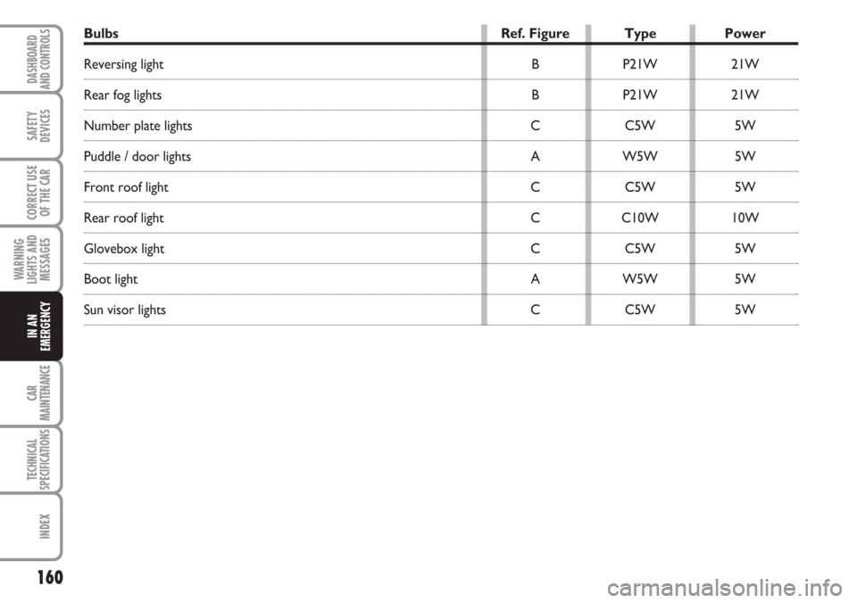
Bulbs Ref. Figure Type Power
Reversing light B P21W 21W
Rear fog lights B P21W 21W
Number plate lights C C5W 5W
Puddle / door lights A W5W 5W
Front roof light C C5W 5W
Rear roof light C C10W 10W
Glovebox light C C5W 5W
Boot light A W5W 5W
Sun visor lights C C5W 5W