Ac unit FIAT DOBLO 2008 1.G Owner's Manual
[x] Cancel search | Manufacturer: FIAT, Model Year: 2008, Model line: DOBLO, Model: FIAT DOBLO 2008 1.GPages: 222, PDF Size: 3.39 MB
Page 115 of 222
114DRIVING YOUR VEHICLE
The tow hitch must comply with the
current regulation, with reference to
Directive 94/20/EC and amendments.
Install a tow hitch which is suitable
for the towing capacity of the vehicle.
Use a unified coupling for the elec-
trical connections. The coupling is gen-
erally fitted on a specific mount fas-
tened to the tow hitch.
For electrical connection, a 7 or 13
pole 12VDC coupling must be used
(CUNA/UNI and ISO/DIN standards).
Follow the instructions provided by
the manufacturer of the vehicle and/or
the tow hitch.
Use the specific trailer light fusebox
for electrical connections.
An electric brake should be supplied
directly by the battery through a cable
with a cross section of no less than 2.5
mm
2.In addition to the electrical connec-
tion, only the lead for powering an
electric brake and the lead to power
a light inside the trailer not exceed-
ing 15W may be connected to the ve-
hicle’s electrical system.
For connections use the preset con-
trol unit with battery cable no less
than 2,5 mm
2.
FITTING DIAGRAM
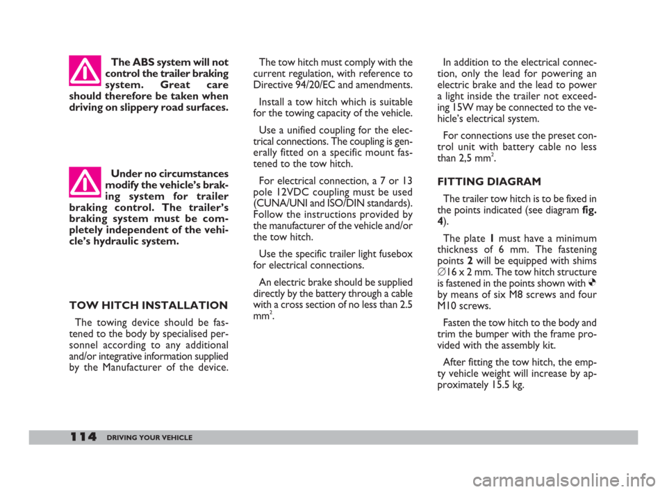
The trailer tow hitch is to be fixed in
the points indicated (see diagram fig.
4).
The plate 1must have a minimum
thickness of 6 mm. The fastening
points 2will be equipped with shims
�’16 x 2 mm. The tow hitch structure
is fastened in the points shown with Ø
by means of six M8 screws and four
M10 screws.
Fasten the tow hitch to the body and
trim the bumper with the frame pro-
vided with the assembly kit.
After fitting the tow hitch, the emp-
ty vehicle weight will increase by ap-
proximately 15.5 kg. The ABS system will not
control the trailer braking
system. Great care
should therefore be taken when
driving on slippery road surfaces.
Under no circumstances
modify the vehicle’s brak-
ing system for trailer
braking control. The trailer’s
braking system must be com-
pletely independent of the vehi-
cle’s hydraulic system.
TOW HITCH INSTALLATION
The towing device should be fas-
tened to the body by specialised per-
sonnel according to any additional
and/or integrative information supplied
by the Manufacturer of the device.
106-118 Doblo GB 9-05-2008 12:09 Pagina 114
Page 121 of 222
120IN AN EMERGENCY
If the battery is flat, you can use an-
other battery to start the engine. Its
capacity must be the same or slightly
greater than the flat battery.
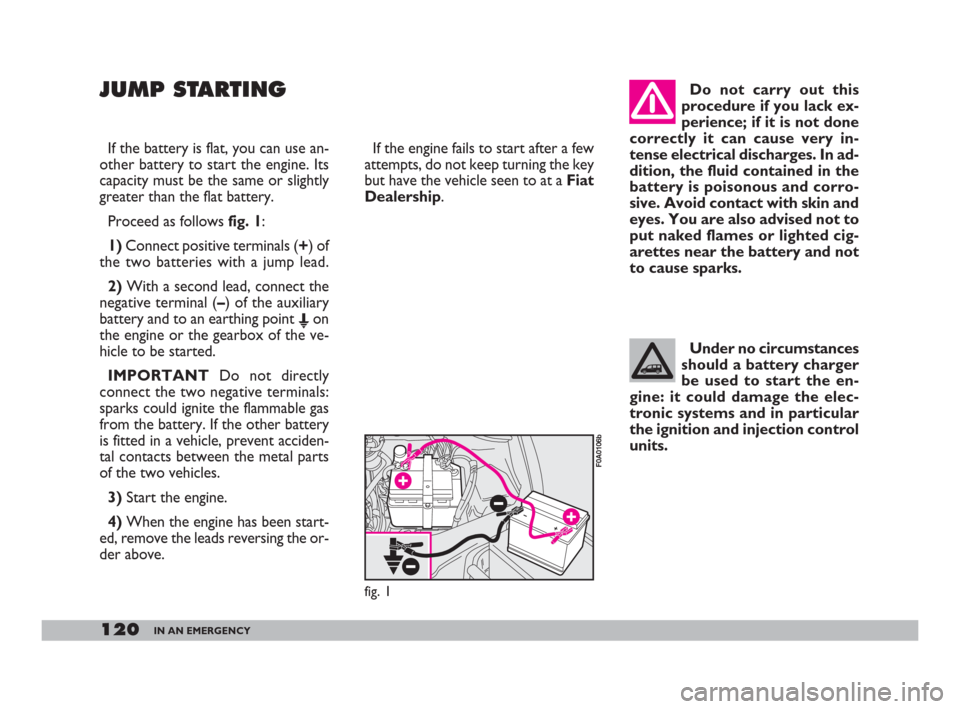
Proceed as follows fig. 1:
1) Connect positive terminals (+) of
the two batteries with a jump lead.
2)With a second lead, connect the
negative terminal (–) of the auxiliary
battery and to an earthing point E
on
the engine or the gearbox of the ve-
hicle to be started.
IMPORTANTDo not directly
connect the two negative terminals:
sparks could ignite the flammable gas
from the battery. If the other battery
is fitted in a vehicle, prevent acciden-
tal contacts between the metal parts
of the two vehicles.
3) Start the engine.
4)When the engine has been start-
ed, remove the leads reversing the or-
der above.If the engine fails to start after a few
attempts, do not keep turning the key
but have the vehicle seen to at a Fiat
Dealership.
JUMP STARTING
fig. 1
F0A0106b
Do not carry out this
procedure if you lack ex-
perience; if it is not done
correctly it can cause very in-
tense electrical discharges. In ad-
dition, the fluid contained in the
battery is poisonous and corro-
sive. Avoid contact with skin and
eyes. You are also advised not to
put naked flames or lighted cig-
arettes near the battery and not
to cause sparks.
Under no circumstances
should a battery charger
be used to start the en-
gine: it could damage the elec-
tronic systems and in particular
the ignition and injection control
units.
119-148 Doblo GB 9-05-2008 12:09 Pagina 120
Page 135 of 222
134IN AN EMERGENCY
REAR LIGHT CLUSTER
To replace a bulb, proceed as fol-
lows:
Versions equipped with rear
brackets:
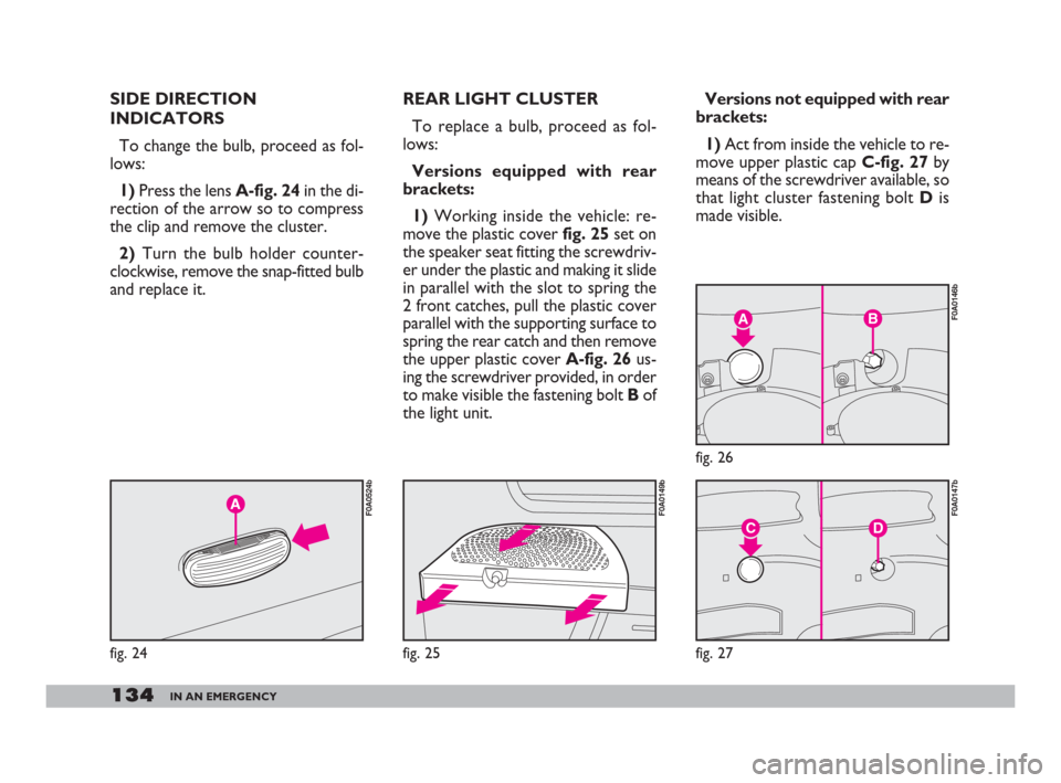
1)Working inside the vehicle: re-
move the plastic cover fig. 25set on
the speaker seat fitting the screwdriv-
er under the plastic and making it slide
in parallel with the slot to spring the
2 front catches, pull the plastic cover
parallel with the supporting surface to
spring the rear catch and then remove
the upper plastic cover A-fig. 26us-
ing the screwdriver provided, in order
to make visible the fastening bolt Bof
the light unit.Versions not equipped with rear
brackets:
1)Act from inside the vehicle to re-
move upper plastic cap C-fig. 27by
means of the screwdriver available, so
that light cluster fastening bolt Dis
made visible.
AB
fig. 26
F0A0146b
DC
fig. 27
F0A0147b
fig. 25
F0A0149b
SIDE DIRECTION
INDICATORS
To change the bulb, proceed as fol-
lows:
1)Press the lens A-fig. 24in the di-
rection of the arrow so to compress
the clip and remove the cluster.
2)Turn the bulb holder counter-
clockwise, remove the snap-fitted bulb
and replace it.
fig. 24
F0A0524b
119-148 Doblo GB 9-05-2008 12:09 Pagina 134
Page 136 of 222
135IN AN EMERGENCY
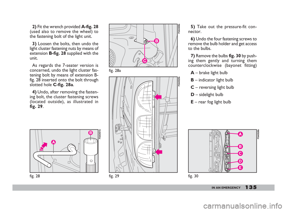
2)Fit the wrench provided A-fig. 28
(used also to remove the wheel) to
the fastening bolt of the light unit.
3)Loosen the bolts, then undo the
light cluster fastening nuts by means of
extension B-fig. 28supplied with the
unit.
As regards the 7-seater version is
concerned, undo the light cluster fas-
tening bolt by means of extension B-
fig. 28 inserted onto the bolt through
slotted hole C-fig. 28a.
4)Undo, after removing the fasten-
ing bolt, the cluster fastening screws
(located outside), as illustrated in
fig. 29.5)Take out the pressure-fit con-
nector.
6)Undo the four fastening screws to
remove the bulb holder and get access
to the bulbs.
7)Remove the bulbs fig. 30by push-
ing them gently and turning them
counterclockwise (bayonet fitting)
A– brake light bulb
B– indicator light bulb
C– reversing light bulb
D– sidelight bulb
E– rear fog light bulb
fig. 28a
F0A0406b
fig. 29
F0A0525b
fig. 30
F0A0526b
fig. 28
F0A0401b
119-148 Doblo GB 9-05-2008 12:09 Pagina 135
Page 142 of 222
141IN AN EMERGENCY
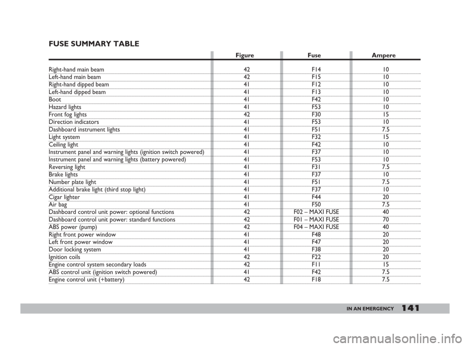
FUSE SUMMARY TABLE
10
10
10
10
10
10
15
10
7.5
15
10
10
10
7.5
10
7.5
10
20
7.5
40
70
40
20
20
20
20
15
7.5
7.5 F14
F15
F12
F13
F42
F53
F30
F53
F51
F32
F42
F37
F53
F31
F37
F51
F37
F44
F50
F02 – MAXI FUSE
F01 – MAXI FUSE
F04 – MAXI FUSE
F48
F47
F38
F22
F11
F42
F18 42
42
41
41
41
41
42
41
41
41
41
41
41
41
41
41
41
41
41
42
42
42
41
41
41
42
42
41
42
Figure Fuse Ampere
Right-hand main beam
Left-hand main beam
Right-hand dipped beam
Left-hand dipped beam
Boot
Hazard lights
Front fog lights
Direction indicators
Dashboard instrument lights
Light system
Ceiling light
Instrument panel and warning lights (ignition switch powered)
Instrument panel and warning lights (battery powered)
Reversing light
Brake lights
Number plate light
Additional brake light (third stop light)
Cigar lighter
Air bag
Dashboard control unit power: optional functions
Dashboard control unit power: standard functions
ABS power (pump)
Right front power window
Left front power window
Door locking system
Ignition coils
Engine control system secondary loads
ABS control unit (ignition switch powered)
Engine control unit (+battery)
119-148 Doblo GB 9-05-2008 12:09 Pagina 141
Page 143 of 222
142IN AN EMERGENCY
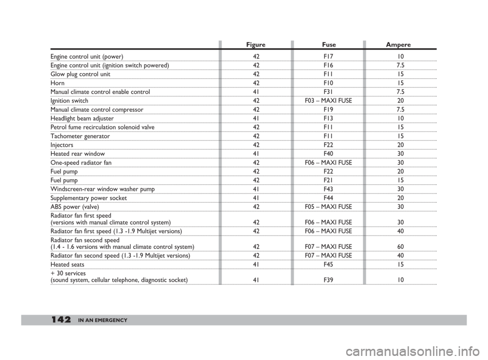
Engine control unit (power)
Engine control unit (ignition switch powered)
Glow plug control unit
Horn
Manual climate control enable control
Ignition switch
Manual climate control compressor
Headlight beam adjuster
Petrol fume recirculation solenoid valve
Tachometer generator
Injectors
Heated rear window
One-speed radiator fan
Fuel pump
Fuel pump
Windscreen-rear window washer pump
Supplementary power socket
ABS power (valve)
Radiator fan first speed
(versions with manual climate control system)
Radiator fan first speed (1.3 -1.9 Multijet versions)
Radiator fan second speed
(1.4 - 1.6 versions with manual climate control system)
Radiator fan second speed (1.3 -1.9 Multijet versions)
Heated seats
+ 30 services
(sound system, cellular telephone, diagnostic socket)
Figure Fuse Ampere
10
7.5
15
15
7.5
20
7.5
10
15
15
20
30
30
20
15
30
20
30
30
40
60
40
15
10 F17
F16
F11
F10
F31
F03 – MAXI FUSE
F19
F13
F11
F11
F22
F40
F06 – MAXI FUSE
F22
F21
F43
F44
F05 – MAXI FUSE
F06 – MAXI FUSE
F06 – MAXI FUSE
F07 – MAXI FUSE
F07 – MAXI FUSE
F45
F39 42
42
42
42
41
42
42
41
42
42
42
41
42
42
42
41
41
42
42
42
42
42
41
41
119-148 Doblo GB 9-05-2008 12:09 Pagina 142
Page 145 of 222
144IN AN EMERGENCY
IF THE BATTERY
IS FLAT
First of all, read the “Vehicle main-
tenance” section for the steps to be
taken to avoid the battery running
down and to ensure it has a long life.
IF THE BATTERY IS FLAT
Charging should be slow at a low
amp rating for 24 hours. Charging for
a longer time may damage the battery.
Proceed as follows:
1) Disconnect the electrical system
from the battery terminals.
IMPORTANTWhere relevant,
switch the electronic alarm off with
the remote control.2)Connect the charger cables to the
battery terminals.
3)Turn on the charger.
4)When you have finished, turn the
charger off before disconnecting the
battery.
5)Reconnect the cables to the bat-
tery terminals. Make sure the polari-
ty is correct.JUMP STARTING
See “Jump starting”, in this chapter.
The liquid in the battery
is poisonous and corro-
sive. Do not let it touch
the skin or eyes. Recharging the
battery should be done in a well-
ventilated area away from naked
flames or possible sources of
sparks: explosion and fire risk.
Do not attempt to
recharge a frozen bat-
tery. Thaw it first other-
wise it could explode. If the bat-
tery froze, make sure that the in-
ternal elements are not broken
(short-circuit risk) and that the
casing is not cracked (risk of
spilling the poisonous and corro-
sive fluid).
Under no circumstances
should a battery charger
be used to start the en-
gine: it could damage the elec-
tronic systems and in particular
the ignition and injection control
units.
119-148 Doblo GB 9-05-2008 12:09 Pagina 144
Page 162 of 222
161VEHICLE MAINTENANCE
IMPORTANTBrake fluid is hy-
groscopic (meaning it absorbs humid-
ity). This is why the fluid should be
changed more frequently than shown
in the service schedule if the vehicle is
mainly driven in areas with a high per-
centage of humidity in the air.
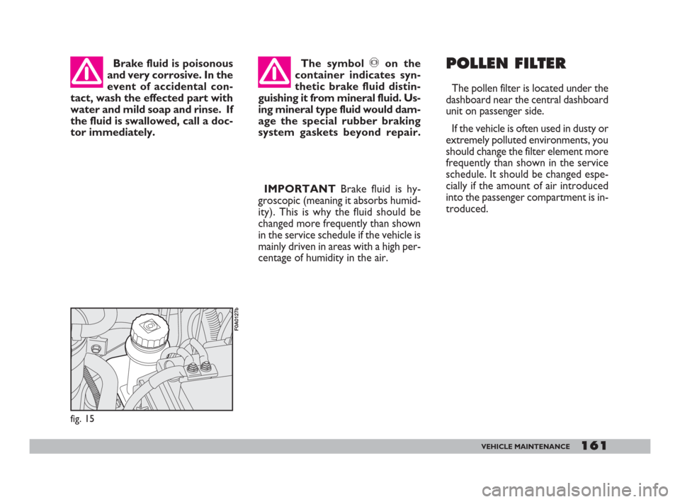
fig. 15
F0A0127b
Brake fluid is poisonous
and very corrosive. In the
event of accidental con-
tact, wash the effected part with
water and mild soap and rinse. If
the fluid is swallowed, call a doc-
tor immediately.The symbol πon the
container indicates syn-
thetic brake fluid distin-
guishing it from mineral fluid. Us-
ing mineral type fluid would dam-
age the special rubber braking
system gaskets beyond repair.POLLEN FILTER
The pollen filter is located under the
dashboard near the central dashboard
unit on passenger side.
If the vehicle is often used in dusty or
extremely polluted environments, you
should change the filter element more
frequently than shown in the service
schedule. It should be changed espe-
cially if the amount of air introduced
into the passenger compartment is in-
troduced.
149-173 Doblo GB 9-05-2008 12:10 Pagina 161
Page 167 of 222
166VEHICLE MAINTENANCE
ELECTRONIC
CONTROL UNITS
When the vehicle is being used nor-
mally, special measures are not neces-
sary.
The following instructions must be
followed very carefully, however, if
you work on the electrical system or
in cases where emergency starting is
necessary:
– Never disconnect the battery from
the electrical system while the engine
is running.
– Disconnect the battery from the
electrical system if you are recharg-
ing it. The modern battery chargers
can discharge voltage up to 20V.
– Never perform emergency start-
ups with a battery charger. Always use
an auxiliary battery.
– Be particularly careful when con-
necting the battery to the electrical
system. Ensure the battery posts are
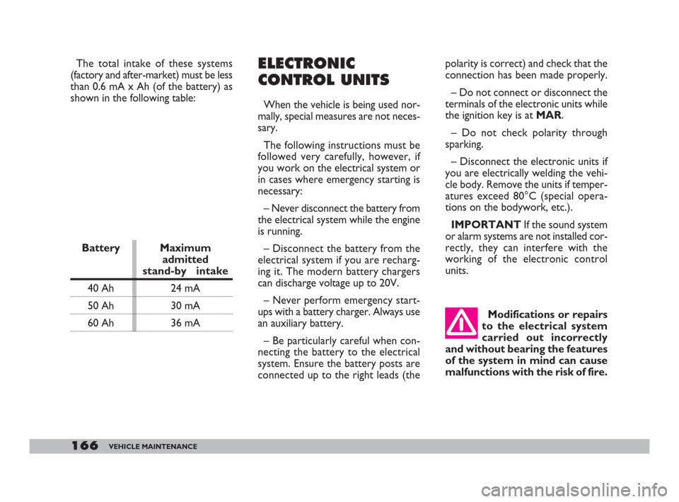
connected up to the right leads (the Battery Maximum
admitted
stand-by intake
40 Ah 24 mA
50 Ah 30 mA
60 Ah 36 mApolarity is correct) and check that the
connection has been made properly.
– Do not connect or disconnect the
terminals of the electronic units while
the ignition key is at MAR.
– Do not check polarity through
sparking.
– Disconnect the electronic units if
you are electrically welding the vehi-
cle body. Remove the units if temper-
atures exceed 80°C (special opera-
tions on the bodywork, etc.).
IMPORTANTIf the sound system
or alarm systems are not installed cor-
rectly, they can interfere with the
working of the electronic control
units.
Modifications or repairs
to the electrical system
carried out incorrectly
and without bearing the features
of the system in mind can cause
malfunctions with the risk of fire.
The total intake of these systems
(factory and after-market) must be less
than 0.6 mA x Ah (of the battery) as
shown in the following table:
149-173 Doblo GB 9-05-2008 12:10 Pagina 166
Page 173 of 222
172VEHICLE MAINTENANCE
Detergents pollute wa-
ter. The vehicle must
therefore be washed in an
area equipped for the collection
and purification of the liquids
used while washing.
IMPORTANT The engine com-
partment should be washed while the
engine is cold and with the ignition key
at STOP. After washing, make sure
that the various protections (e.g. rub-
ber boots and various guards) have
not be removed or damaged. To wash the vehicle properly:
1) Remove the aerial from the roof
to prevent damaging it when washing
the vehicle in an automatic carwash.
2) Wash the body using a low pres-
sure jet of water.
3)Wipe a sponge with a slightly
soapy solution over the bodywork,
frequently rinsing the sponge.
4)Rinse well with water and dry
with a jet of air or a chamois leather.
When drying the vehicle, be careful
to get at those parts which are not so
easily seen e.g. the door frames, bon-
net and around the headlights where
water can most readily collect. You
should leave the vehicle out in the
open so that any water remaining can
evaporate more easily.Detergents pollute wa-
ter. For this reason, the
vehicle must be washed in
an area equipped for the collec-
tion and purification of the liquids
used while washing.
Engine compartment
At the end of each winter season,
carefully clean the engine compart-
ment. Be careful not to direct the jet
of water on the electronic control
units. Have this done at a garage. Do not wash the vehicle after it has
been parked in the sun or while the
bonnet is hot: it could take the shine
off the paint.
Outside plastic parts must be cleaned
following the usual vehicle washing
procedure.
Where possible avoid parking the ve-
hicle under trees; the resinous sub-
stances that certain species of tree
shed dull the paintwork and increase
the possibility of rust forming.
IMPORTANTBird droppings must
be washed off immediately and with
great care as their acid is particularly
aggressive.
Windows
Use specific window cleaner prod-
ucts to clean cloths to avoid scratch-
ing the glass or damaging the trans-
parency.
IMPORTANTTo prevent damage
to the electric heater element, wipe the
inside of the heated rear window gen-
tly in the same direction as the ele-
ments.
149-173 Doblo GB 9-05-2008 12:10 Pagina 172