Right light FIAT DOBLO 2009 2.G Owner's Manual
[x] Cancel search | Manufacturer: FIAT, Model Year: 2009, Model line: DOBLO, Model: FIAT DOBLO 2009 2.GPages: 274, PDF Size: 6.6 MB
Page 88 of 274
87
KNOW
YOUR
VEHICLE
SAFETY
STARTING
AND
DRIVING
WARNING
LIGHTS AND
MESSAGES
IN AN
EMERGENCY
SERVICING
AND
MAINTENANCE
TECHNICAL
SPECIFICATIONS
INDEX
or
❒open the sliding side door (Cargo versions);
❒use device A-fig. 86 located on the inside of the right-
hand swing door;
❒open the left-hand swing door by pulling on its handle
(see “Doors” in this section).
If you are travelling in areas with few re-
fuelling stations and you want to transport
fuel in a spare tank, comply with the law by us-
ing only an approved, suitably secured tank. Even
then, you are still increasing the risk of fire in an
accident.
WARNING
Never exceed the maximum allowed load
in the boot (see “Technical Specifications”).
Make sure that objects are well arranged in the
boot so that they do not project forwards and in-
jure passengers in the event of sudden braking.
WARNING
Page 116 of 274
115
KNOW
YOUR
VEHICLE
SAFETY
STARTING
AND
DRIVING
WARNING
LIGHTS AND
MESSAGES
IN AN
EMERGENCY
SERVICING
AND
MAINTENANCE
TECHNICAL
SPECIFICATIONS
INDEX
F0V0023mfig. 110
Through the reel, the belt automatically adapts to the body
of the passenger wearing it, allowing freedom of move-
ment.
The reel may lock up when the vehicle is parked on a steep
slope: this is perfectly normal. Furthermore, the reel mech-
anism locks the belt if it is pulled sharply or in the event
of sudden braking, collisions and high-speed bends.SEAT BELTS
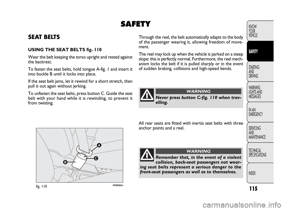
USING THE SEAT BELTS fig. 110
Wear the belt keeping the torso upright and rested against
the backrest.
To fasten the seat belts, hold tongue A-fig. 1 and insert it
into buckle B until it locks into place.
If the seat belt jams, let it rewind for a short stretch, then
pull it out again without jerking.
To unfasten the seat belts, press button C. Guide the seat
belt with your hand while it is rewinding, to prevent it
from twisting.
SAFETY
Never press button C-fig. 110 when trav-
elling.
WARNING
All rear seats are fitted with inertia seat belts with three
anchor points and a reel.
Remember that, in the event of a violent
collision, back-seat passengers not wear-
ing seat belts represent a serious danger to the
front-seat passengers as well as to themselves.
WARNING
Page 137 of 274

136
KNOW
YOUR
VEHICLE
SAFETY
STARTING
AND
DRIVING
WARNING
LIGHTS AND
MESSAGES
IN AN
EMERGENCY
SERVICING
AND
MAINTENANCE
TECHNICAL
SPECIFICATIONS
INDEX
F0V0069mfig. 127F0V0087mfig. 126
PARKING THE VEHICLE
Proceed as follows:
❒stop the engine and engage the handbrake;
❒engage a gear (first gear if parked uphill or reverse if
facing downhill) and leave the wheels turned.
If the vehicle is parked on a steep slope, it is advisable to
block the wheels with a wedge or stone.
To prevent draining the battery, do not leave the ignition
key turned to MAR. Always remove the key when you
leave the vehicle.
Never leave children unattended in the vehicle. Always
remove the ignition key when leaving the vehicle, and take
it with you.
USING THE GEARBOX
To engage the gears, depress the clutch pedal fully and
shift the gear lever A-fig. 127 into the required position
(the diagram is shown on the gear knob fig. 127).
IMPORTANT Reverse may be engaged only when the ve-
hicle is at a standstill. With the engine running, wait for
at least 2 seconds with the clutch pedal fully depressed
before engaging reverse to prevent damage to the gears
and grating.
To engage reverse R from neutral, lift ring B under the
knob and at the same time move the gearstick to the right
and then backwards (as shown in the diagram).
Page 155 of 274
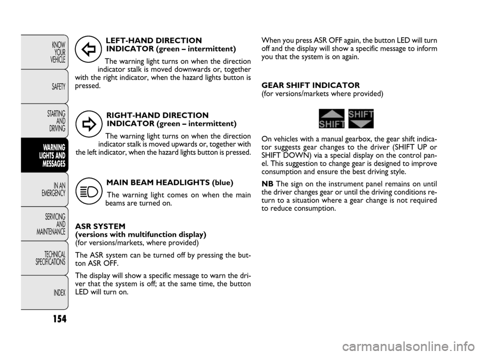
RIGHT-HAND DIRECTION
INDICATOR (green – intermittent)
The warning light turns on when the direction
indicator stalk is moved upwards or, together with
the left indicator, when the hazard lights button is pressed.
154
KNOW
YOUR
VEHICLE
SAFETY
STARTING
AND
DRIVING
WARNING
LIGHTS AND
MESSAGES
IN AN
EMERGENCY
SERVICING
AND
MAINTENANCE
TECHNICAL
SPECIFICATIONS
INDEXLEFT-HAND DIRECTION
INDICATOR (green – intermittent)
The warning light turns on when the direction
indicator stalk is moved downwards or, together
with the right indicator, when the hazard lights button is
pressed.
MAIN BEAM HEADLIGHTS (blue)
The warning light comes on when the main
beams are turned on.
ASR SYSTEM
(versions with multifunction display)
(for versions/markets, where provided)
The ASR system can be turned off by pressing the but-
ton ASR OFF.
The display will show a specific message to warn the dri-
ver that the system is off; at the same time, the button
LED will turn on.
Î
¥
1
When you press ASR OFF again, the button LED will turn
off and the display will show a specific message to inform
you that the system is on again.
GEAR SHIFT INDICATOR
(for versions/markets where provided)
On vehicles with a manual gearbox, the gear shift indica-
tor suggests gear changes to the driver (SHIFT UP or
SHIFT DOWN) via a special display on the control pan-
el. This suggestion to change gear is designed to improve
consumption and ensure the best driving style.
NBThe sign on the instrument panel remains on until
the driver changes gear or until the driving conditions re-
turn to a situation where a gear change is not required
to reduce consumption.
Page 159 of 274
F0V0148mfig. 130
F0V0149mfig. 129
158
KNOW
YOUR
VEHICLE
SAFETY
STARTING
AND
DRIVING
WARNING
LIGHTS AND
MESSAGES
IN AN
EMERGENCY
SERVICING
AND
MAINTENANCE
TECHNICAL
SPECIFICATIONS
INDEXImportant notes:
❒ the jack weighs 4 kg;
❒the jack requires no adjustment;
❒the jack cannot be repaired; if it breaks, it must be re-
placed with a new one of the same type;
❒no tool other than the cranking handle may be fitted
on the jack.
To change a tyre, proceed as follows:
❒stop the vehicle in a position where it is not a danger
for other traffic and where you can replace the wheel
safely. The ground should be flat and solid;
❒turn the engine off and engage the handbrake;
❒engage first gear or reverse;
❒wear the reflective safety jacket (compulsory by law)
before getting out of the vehicle;
❒ indicate that the vehicle is parked up by using the de-
vices required by law in the country in which you are
travelling (e.g. warning triangle, hazard lights etc.);
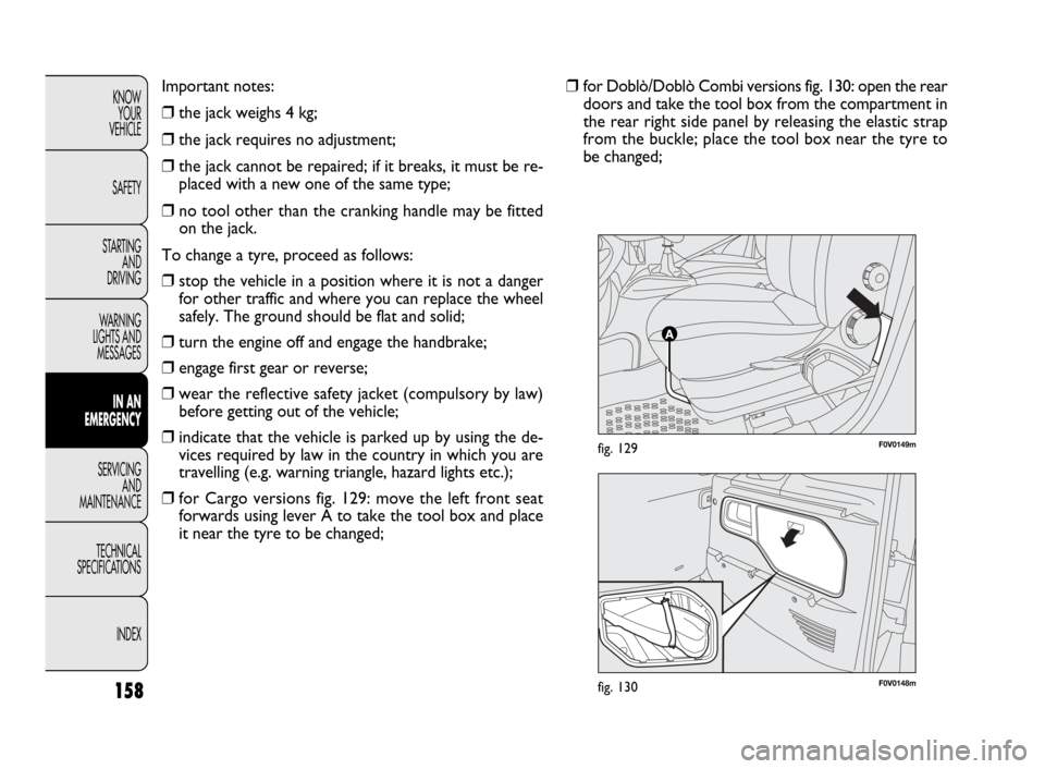
❒for Cargo versions fig. 129: move the left front seat
forwards using lever A to take the tool box and place
it near the tyre to be changed;❒for Doblò/Doblò Combi versions fig. 130: open the rear
doors and take the tool box from the compartment in
the rear right side panel by releasing the elastic strap
from the buckle; place the tool box near the tyre to
be changed;
Page 163 of 274
162
KNOW
YOUR
VEHICLE
SAFETY
STARTING
AND
DRIVING
WARNING
LIGHTS AND
MESSAGES
IN AN
EMERGENCY
SERVICING
AND
MAINTENANCE
TECHNICAL
SPECIFICATIONS
INDEX
F0V0158mfig. 139F0V0194fig. 140
❒put the jack and the other implements back in the tool
box.
❒position the tool box behind the left seat (Cargo ver-
sions) or inside the compartment in the rear right side
panel by resting the base of the box on the side
(Doblò/Doblò Combi versions);
❒secure the tool box with the elastic strap and fasten
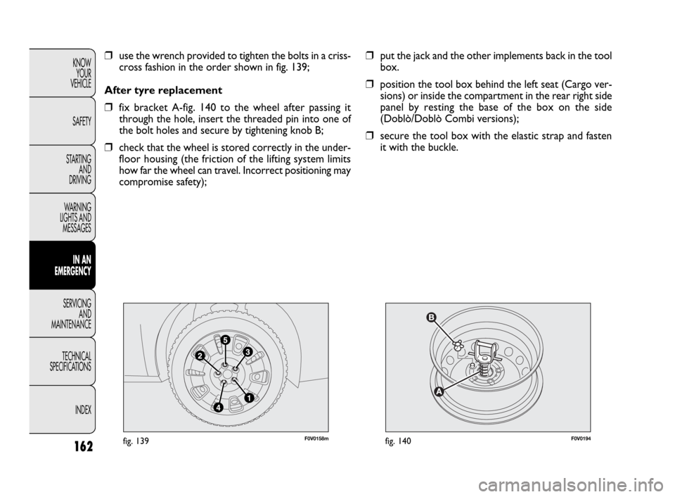
it with the buckle. ❒use the wrench provided to tighten the bolts in a criss-
cross fashion in the order shown in fig. 139;
After tyre replacement
❒fix bracket A-fig. 140 to the wheel after passing it
through the hole, insert the threaded pin into one of
the bolt holes and secure by tightening knob B;
❒check that the wheel is stored correctly in the under-
floor housing (the friction of the lifting system limits
how far the wheel can travel. Incorrect positioning may
compromise safety);
Page 164 of 274
163
KNOW
YOUR
VEHICLE
SAFETY
STARTING
AND
DRIVING
WARNING
LIGHTS AND
MESSAGES
IN AN
EMERGENCY
SERVICING
AND
MAINTENANCE
TECHNICAL
SPECIFICATIONS
INDEX
F0V0093mfig. 141F0V0094mfig. 142
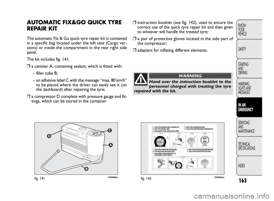
❒instruction booklet (see fig. 142), used to ensure the
correct use of the quick tyre repair kit and then given
to whoever will handle the treated tyre;
❒a pair of protective gloves located in the side part of
the compressor;
❒adapters for inflating different elements.
AUTOMATIC FIX&GO QUICK TYRE
REPAIR KIT
The automatic Fix & Go quick tyre repair kit is contained
in a specific bag located under the left seat (Cargo ver-
sions) or inside the compartment in the rear right side
panel.
The kit includes fig. 141:
❒a canister A, containing sealant, which is fitted with:
– filler tube B;
– an adhesive label C with the message “max. 80 km/h”
to be placed where the driver can easily see it (on
the dashboard) after repairing the tyre;
❒a compressor D complete with pressure gauge and fit-
tings, which can be stored in the container
Hand over the instruction booklet to the
personnel charged with treating the tyre
repaired with the kit.
WARNING
Page 183 of 274
182
KNOW
YOUR
VEHICLE
SAFETY
STARTING
AND
DRIVING
WARNING
LIGHTS AND
MESSAGES
IN AN
EMERGENCY
SERVICING
AND
MAINTENANCE
TECHNICAL
SPECIFICATIONS
INDEX
F0V0081mfig. 174
F0V0089mfig. 175
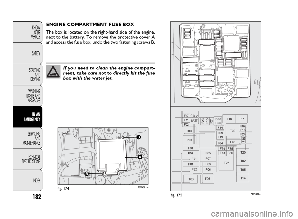
ENGINE COMPARTMENT FUSE BOX
The box is located on the right-hand side of the engine,
next to the battery. To remove the protective cover A
and access the fuse box, undo the two fastening screws B.
If you need to clean the engine compart-
ment, take care not to directly hit the fuse
box with the water jet.
Page 188 of 274
187
KNOW
YOUR
VEHICLE
SAFETY
STARTING
AND
DRIVING
WARNING
LIGHTS AND
MESSAGES
IN AN
EMERGENCY
SERVICING
AND
MAINTENANCE
TECHNICAL
SPECIFICATIONS
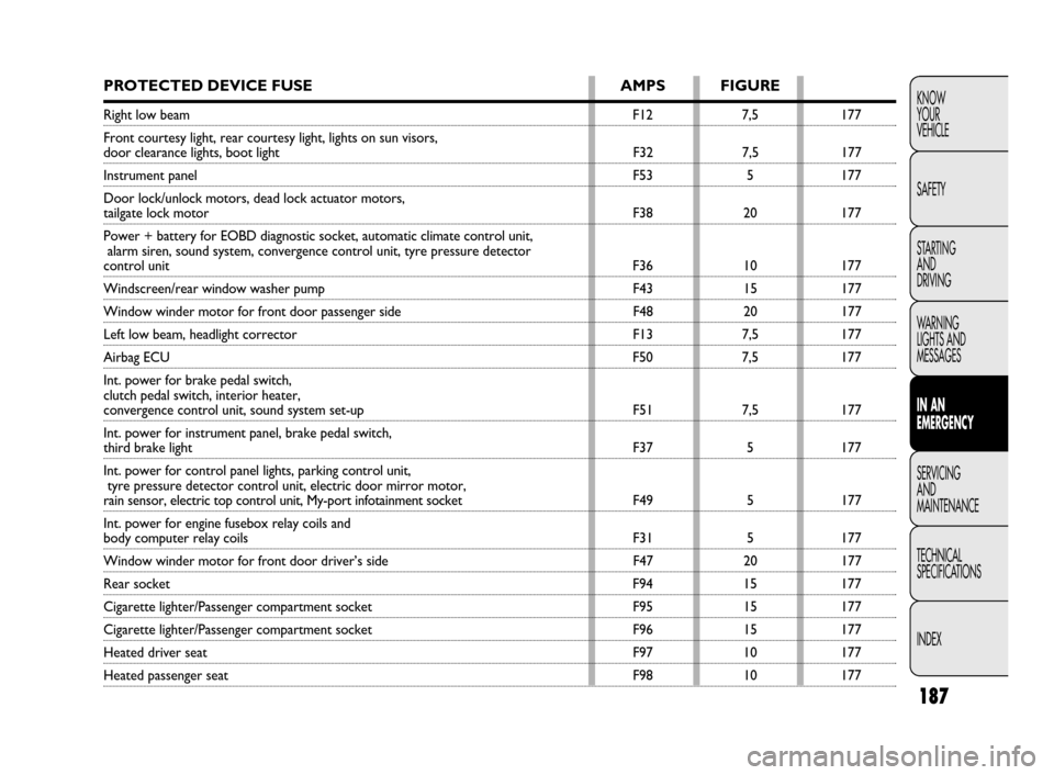
INDEXPROTECTED DEVICE FUSE AMPS FIGURE
Right low beamF12 7,5 177
Front courtesy light, rear courtesy light, lights on sun visors,
door clearance lights, boot light F32 7,5 177
Instrument panel F53 5 177
Door lock/unlock motors, dead lock actuator motors,
tailgate lock motor F38 20 177
Power + battery for EOBD diagnostic socket, automatic climate control unit,
alarm siren, sound system, convergence control unit, tyre pressure detector
control unitF36 10 177
Windscreen/rear window washer pump F43 15 177
Window winder motor for front door passenger side F48 20 177
Left low beam, headlight corrector F13 7,5 177
Airbag ECUF50 7,5 177
Int. power for brake pedal switch,
clutch pedal switch, interior heater,
convergence control unit, sound system set-up F51 7,5 177
Int. power for instrument panel, brake pedal switch,
third brake light F37 5 177
Int. power for control panel lights, parking control unit,
tyre pressure detector control unit, electric door mirror motor,
rain sensor, electric top control unit, My-port infotainment socket F49 5 177
Int. power for engine fusebox relay coils and
body computer relay coils F31 5 177
Window winder motor for front door driver’s side F47 20 177
Rear socketF94 15 177
Cigarette lighter/Passenger compartment socket F95 15 177
Cigarette lighter/Passenger compartment socket F96 15 177
Heated driver seat F97 10 177
Heated passenger seat F98 10 177
Page 211 of 274
210
KNOW
YOUR
VEHICLE
SAFETY
STARTING
AND
DRIVING
WARNING
LIGHTS AND
MESSAGES
IN AN
EMERGENCY
SERVICING
AND
MAINTENANCE
TECHNICAL
SPECIFICATIONS
INDEX❒In case of replacement, always fit new tyres, avoiding
those with an unknown origin.
❒If a tyre is replaced, you should also change the infla-
tion valve.
❒to allow even wear between the front and rear tyres,
it is advisable to switch them every 10-15 thousand kilo-
metres, keeping them on the same side of the car so
as not to reverse the direction of rotation.
Remember that road hold depends on cor-
rect tyre pressures.
WARNING
If the pressure is too low, the tyre
overheats and this can cause it serious
damage.
WARNING
Do not switch the tyres from the right of
the vehicle to the left and vice versa.
WARNING
Do not re-spray alloy wheel rims at tem-
peratures higher than 150 °C. The me-
chanical characteristics of the wheels may be
compromised.
WARNING