tyre pressure FIAT DOBLO 2009 2.G Owners Manual
[x] Cancel search | Manufacturer: FIAT, Model Year: 2009, Model line: DOBLO, Model: FIAT DOBLO 2009 2.GPages: 274, PDF Size: 6.6 MB
Page 99 of 274
98
KNOW
YOUR
VEHICLE
SAFETY
STARTING
AND
DRIVING
WARNING
LIGHTS AND
MESSAGES
IN AN
EMERGENCY
SERVICING
AND
MAINTENANCE
TECHNICAL
SPECIFICATIONS
INDEX
ESP SYSTEM
(Electronic Stability Program)
(for versions/markets where provided)
This is an electronic system that controls vehicle stability
in the event of tyre grip loss, helping to maintain direc-
tional control.
The ESP system is therefore particularly useful when grip
conditions of road surfaces change.
The MSR system (adjustment of the engine braking torque
during gear downshifts) and the HBA system (automatic
increase in the braking pressure during emergency brak-
ing) are present with ESP, ASR and Hill Holder systems
(for versions/markets where provided).
SYSTEM INTERVENTION
This is signalled by the flashing of warning light
áin the in-
strument panel, to inform the driver that the vehicle is in
critical stability and grip conditions.
SYSTEM ACTIVATION
The ESP system is automatically activated when the vehi-
cle is started and cannot be de-activated. BRAKE ASSIST (emergency braking assistance
integrated in ESP)
(for versions/markets where provided)
This system (which cannot be deactivated) recognises
emergency braking conditions according to the speed of
operation of the brake pedal and provides an additional
hydraulic braking pressure to support that provided by the
driver. This allows faster and more powerful operation
of the braking system.
Brake Assist is deactivated on the versions equipped with
ESP, in the event of ESP system failure (indicated by warn-
ing light
ácoming on together with the message in the
multifunction display, where provided).
When the ABS cuts in, and you feel the
brake pedal pulsating, do not remove your
foot, but keep it pressed; in doing so you will stop
in the shortest distance possible under the road
conditions at the time.
WARNING
Page 100 of 274
99
KNOW
YOUR
VEHICLE
SAFETY
STARTING
AND
DRIVING
WARNING
LIGHTS AND
MESSAGES
IN AN
EMERGENCY
SERVICING
AND
MAINTENANCE
TECHNICAL
SPECIFICATIONS
INDEX
At pick-up, the ESP system control unit will maintain the
braking pressure at the wheels until the necessary engine
torque for moving away is reached or, in any case, for a
maximum of 1.75 seconds in order to move easily from
the brake pedal to the accelerator pedal.
If the vehicle has not departed after this time, the system
will deactivate automatically by gradually releasing the brak-
ing pressure.
During this release stage, the typical brake disengagement
noise indicating that the vehicle is going to move immi-
nently will be heard.
Failure indications
System failure is indicated by the turning on of warning
light
*in the instrument panel with digital display and
warning light
áin the instrument panel with multifunction
display (for versions/markets where provided) (see sec-
tion “Warning lights and messages”).
IMPORTANT The Hill Holder system is not a parking
brake; therefore, never leave the vehicle without having
engaged the handbrake, turned the engine off and engaged
the first gear. FAILURE INDICATIONS
In the event of a failure, the ESP will be automatically
switched off and the
áwarning light will come on per-
manently in the instrument panel along with a message in
the multifunction display (for versions/markets where pro-
vided) (see “Warning lights and messages” section). The
LED on the ASR OFF button will also light up. Contact the
Fiat Service Network as soon as possible if this happens.
Do not take unnecessary risks, even if your
vehicle is fitted with an ESP system. Your
driving style must always be suited to the road
conditions, visibility and traffic. The driver is al-
ways ultimately responsible for road safety.
WARNING
HILL HOLDER SYSTEM
This is an integral part of the ESP system and facilitates
hill starts. It is automatically activated in the following con-
ditions:
❒uphill: vehicle stationary on a road with a gradient high-
er than 5%, engine running, brake pedal pressed and
gearbox in neutral or gear other than reverse;
❒downhill: vehicle stationary on a road with a gradient
higher than 5 per cent, engine running, brake pedal de-
pressed and reverse gear engaged. For the correct operation of the ESP and
ASR systems, the tyres must absolutely be
the same make and type on all wheels, in perfect
condition and, above all, of the type, make and
size specified.
WARNING
Page 138 of 274
137
KNOW
YOUR
VEHICLE
SAFETY
STARTING
AND
DRIVING
WARNING
LIGHTS AND
MESSAGES
IN AN
EMERGENCY
SERVICING
AND
MAINTENANCE
TECHNICAL
SPECIFICATIONS
INDEXDepress the clutch pedal fully to change
gear correctly. Therefore, the floor area
under the pedals should be clear: ensure that any
rubber mats are flat and do not interfere with the
pedals.
WARNING
Do not drive with your hand resting on the
gear lever, because this pressure, even if
light, can wear out the inner components
of the gearbox over time. The clutch pedal should
be used only for gear changes. Do not drive with
your foot resting on the clutch pedal, however
slightly. For versions/markets where provided, the
electronic clutch control could cut in by interpret-
ing the incorrect driving style as a fault.
SAVING FUEL
Here are some useful tips to save fuel and minimise harm-
ful emissions of CO
2and other pollutants (nitric oxides,
unburnt hydrocarbons, fine dusts etc…).
PRACTICAL ADVICE FOR REDUCING FUEL
CONSUMPTION AND HARMFUL EMISSIONS
Vehicle conditions
1. Have checks and adjustments carried out in
accordance with the “Scheduled Servicing Plan”.
2. Check tyre pressures regularly, at least once every
four weeks. Excessively low pressures will increase
consumption because rolling resistance will be high-
er. In addition, this wears the tyre more quickly and
impairs performance.
3. Only use snow tyreswhen the weather conditions
make them absolutely necessary. They increase con-
sumption and noise.
4. Do not travel with a heavy load: the weight of the
vehicle (especially when driving in town) and its trim
greatly affect fuel consumption and stability.
Page 141 of 274
140
KNOW
YOUR
VEHICLE
SAFETY
STARTING
AND
DRIVING
WARNING
LIGHTS AND
MESSAGES
IN AN
EMERGENCY
SERVICING
AND
MAINTENANCE
TECHNICAL
SPECIFICATIONS
INDEXSNOW TYRES
A Fiat Dealership will be happy to provide advice con-
cerning the most suitable type of tyre for the customer’s
requirements.
For the type, pressures and specifications of the snow
tyre to be used, follow carefully the instructions given in
the “Wheels” paragraph of the “Technical specifications”
section.
The winter performance of these tyres is considerably
reduced when the tread thickness is less than 4 mm. If
this is the case, replace them.
Due to their specific features, the performance of snow
tyres is much lower than that of standard tyres in normal
conditions or on long motorway stretches. You should
therefore use them only in the conditions for which they
were designed.
IMPORTANT When using snow tyres with a maximum
speed index below the one that can be reached by the
vehicle (increased by 5%), place a notice in the passenger
compartment, plainly in view, which states the maximum
speed allowed by the snow tyres (as per EC Directive).
All four tyres should be the same (brand and profile) to
ensure greater safety when driving and braking as well as
making the car more responsive.
Remember that you should not change the rotation di-
rection of the tyres.The ABS with which the vehicle may be
equipped will not control the braking sys-
tem of the trailer. Particular caution is therefore
required on slippery roads.
WARNING
Never modify the braking system of the
vehicle to control the trailer brake. The
trailer braking system must be fully independent
from the hydraulic system of the vehicle.
WARNING
Page 143 of 274

142
KNOW
YOUR
VEHICLE
SAFETY
STARTING
AND
DRIVING
WARNING
LIGHTS AND
MESSAGES
IN AN
EMERGENCY
SERVICING
AND
MAINTENANCE
TECHNICAL
SPECIFICATIONS
INDEX❒sprinkle talcum powder on the rubber windscreen and
rear window wiper blades and lift them off the glass;
❒open the windows slightly;
❒cover the vehicle with a piece of fabric or perforated
plastic sheet; Do not use compact plastic tarpaulins,
which prevent humidity from evaporating from the sur-
face of the vehicle;
❒inflate tyres to a pressure of +0.5 bar above the nor-
mal specified pressure and check regularly;
❒do not drain the engine cooling system.
VEHICLE INACTIVITY
If the vehicle needs to be off the road for longer than one
month, the following precautions must be taken:
❒park the vehicle indoors in a dry and, if possible, well-
ventilated place;
❒engage a gear and check that the handbrake is not on;
❒disconnect the battery negative terminal and check the
charge (see “Battery” in the “Servicing and mainte-
nance”)
❒clean and protect the painted parts using protective
wax;
❒clean and protect the shiny metal parts using special
compounds readily available;
Page 158 of 274
157
KNOW
YOUR
VEHICLE
SAFETY
STARTING
AND
DRIVING
WARNING
LIGHTS AND
MESSAGES
IN AN
EMERGENCY
SERVICING
AND
MAINTENANCE
TECHNICAL
SPECIFICATIONS
INDEXThe spare wheel (where provided) is
specifically for your vehicle. Therefore, it
must not be used on other models. Do not use
spare wheels of other models on your vehicle. The
spare wheel should be used only in an emergency.
Use it as little as possible.
WARNING
Use your hazard lights, warning triangle,
etc to show that your car is stationary.
Passengers should get out of the car, particularly
if it is heavily loaded, and wait for the wheel to
be changed away from the traffic. If you are on
a steep slope or uneven surface, place wedges or
other suitable objects under the wheels to secure
the vehicle. Repair and refit the standard wheel
as soon as possible. Do not grease the bolt threads
before you fit them, because they could sudden-
ly come loose.
WARNING
Use the jack only to replace wheels on the
vehicle with which it is supplied or on oth-
er vehicles of the same model. Never use the jack
for other purposes, such as lifting other models.
Never use the jack to carry out repairs under the
vehicle. Incorrect positioning of the jack may
cause the lifted vehicle to fall. Do not use the jack
for loads higher than the one shown on its label.
WARNING
Incorrect hub cap assembly may cause it
to come off when the car is moving. Nev-
er tamper with the inflation valve. Never intro-
duce tools of any kind between the rim and the
tyre. Check tyre and spare wheel pressures regu-
larly, referring to the values shown in the “Tech-
nical specifications” section.
WARNING
Page 164 of 274
163
KNOW
YOUR
VEHICLE
SAFETY
STARTING
AND
DRIVING
WARNING
LIGHTS AND
MESSAGES
IN AN
EMERGENCY
SERVICING
AND
MAINTENANCE
TECHNICAL
SPECIFICATIONS
INDEX
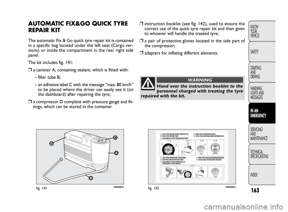
F0V0093mfig. 141F0V0094mfig. 142
❒instruction booklet (see fig. 142), used to ensure the
correct use of the quick tyre repair kit and then given
to whoever will handle the treated tyre;
❒a pair of protective gloves located in the side part of
the compressor;
❒adapters for inflating different elements.
AUTOMATIC FIX&GO QUICK TYRE
REPAIR KIT
The automatic Fix & Go quick tyre repair kit is contained
in a specific bag located under the left seat (Cargo ver-
sions) or inside the compartment in the rear right side
panel.
The kit includes fig. 141:
❒a canister A, containing sealant, which is fitted with:
– filler tube B;
– an adhesive label C with the message “max. 80 km/h”
to be placed where the driver can easily see it (on
the dashboard) after repairing the tyre;
❒a compressor D complete with pressure gauge and fit-
tings, which can be stored in the container
Hand over the instruction booklet to the
personnel charged with treating the tyre
repaired with the kit.
WARNING
Page 167 of 274
166
KNOW
YOUR
VEHICLE
SAFETY
STARTING
AND
DRIVING
WARNING
LIGHTS AND
MESSAGES
IN AN
EMERGENCY
SERVICING
AND
MAINTENANCE
TECHNICAL
SPECIFICATIONS
INDEX
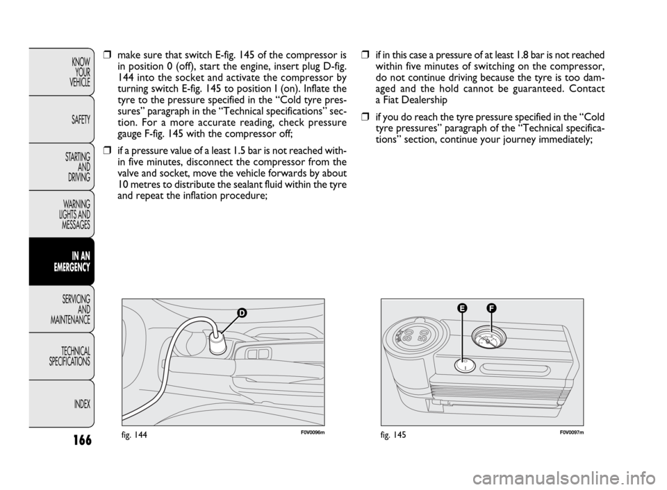
F0V0096mfig. 144F0V0097mfig. 145
❒if in this case a pressure of at least 1.8 bar is not reached
within five minutes of switching on the compressor,
do not continue driving because the tyre is too dam-
aged and the hold cannot be guaranteed. Contact
a Fiat Dealership
❒if you do reach the tyre pressure specified in the “Cold
tyre pressures” paragraph of the “Technical specifica-
tions” section, continue your journey immediately; ❒make sure that switch E-fig. 145 of the compressor is
in position 0 (off), start the engine, insert plug D-fig.
144 into the socket and activate the compressor by
turning switch E-fig. 145 to position I (on). Inflate the
tyre to the pressure specified in the “Cold tyre pres-
sures” paragraph in the “Technical specifications” sec-
tion. For a more accurate reading, check pressure
gauge F-fig. 145 with the compressor off;
❒if a pressure value of a least 1.5 bar is not reached with-
in five minutes, disconnect the compressor from the
valve and socket, move the vehicle forwards by about
10 metres to distribute the sealant fluid within the tyre
and repeat the inflation procedure;
Page 168 of 274
167
KNOW
YOUR
VEHICLE
SAFETY
STARTING
AND
DRIVING
WARNING
LIGHTS AND
MESSAGES
IN AN
EMERGENCY
SERVICING
AND
MAINTENANCE
TECHNICAL
SPECIFICATIONS
INDEX
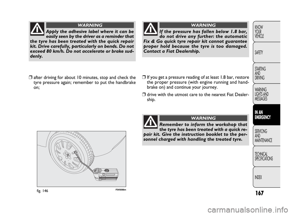
F0V0098mfig. 146
❒If you get a pressure reading of at least 1.8 bar, restore
the proper pressure (with engine running and hand-
brake on) and continue your journey.
❒drive with the utmost care to the nearest Fiat Dealer-
ship. ❒after driving for about 10 minutes, stop and check the
tyre pressure again; remember to put the handbrake
on;
Apply the adhesive label where it can be
easily seen by the driver as a reminder that
the tyre has been treated with the quick repair
kit. Drive carefully, particularly on bends. Do not
exceed 80 km/h. Do not accelerate or brake sud-
denly.
WARNING
If the pressure has fallen below 1.8 bar,
do not drive any further: the automatic
Fix & Go quick tyre repair kit cannot guarantee
proper hold because the tyre is too damaged.
Contact a Fiat Dealership.
WARNING
Remember to inform the workshop that
the tyre has been treated with a quick re-
pair kit. Give the instruction booklet to the per-
sonnel charged with handling the treated tyre.
WARNING
Page 169 of 274
168
KNOW
YOUR
VEHICLE
SAFETY
STARTING
AND
DRIVING
WARNING
LIGHTS AND
MESSAGES
IN AN
EMERGENCY
SERVICING
AND
MAINTENANCE
TECHNICAL
SPECIFICATIONS
INDEX
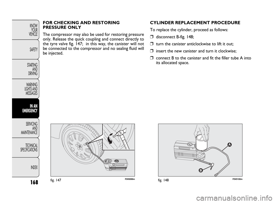
F0V0099mfig. 147F0V0100mfig. 148
CYLINDER REPLACEMENT PROCEDURE
To replace the cylinder, proceed as follows:
❒disconnect B-fig. 148;
❒turn the canister anticlockwise to lift it out;
❒insert the new canister and turn it clockwise;
❒connect B to the canister and fit the filler tube A into
its allocated space. FOR CHECKING AND RESTORING
PRESSURE ONLY
The compressor may also be used for restoring pressure
only. Release the quick coupling and connect directly to
the tyre valve fig. 147; in this way, the canister will not
be connected to the compressor and no sealing fluid will
be injected.